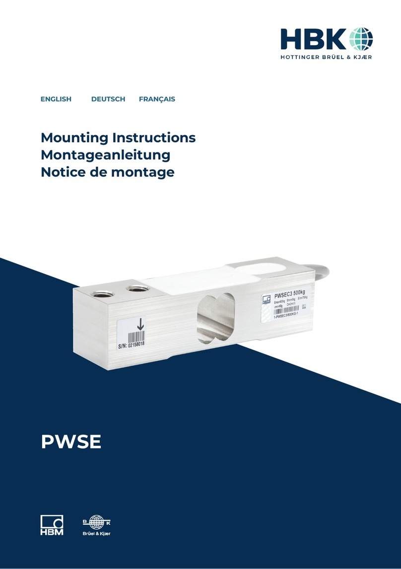
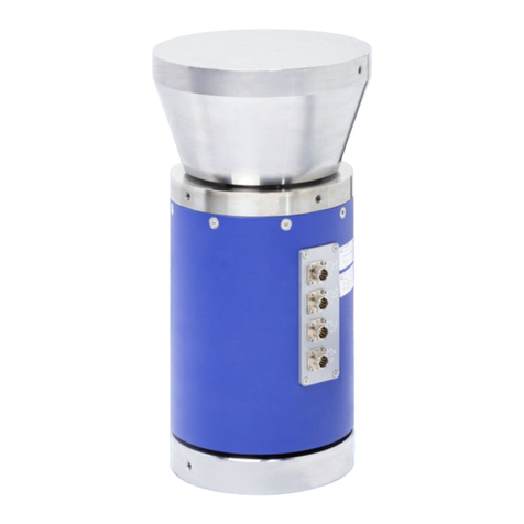
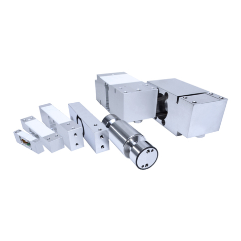
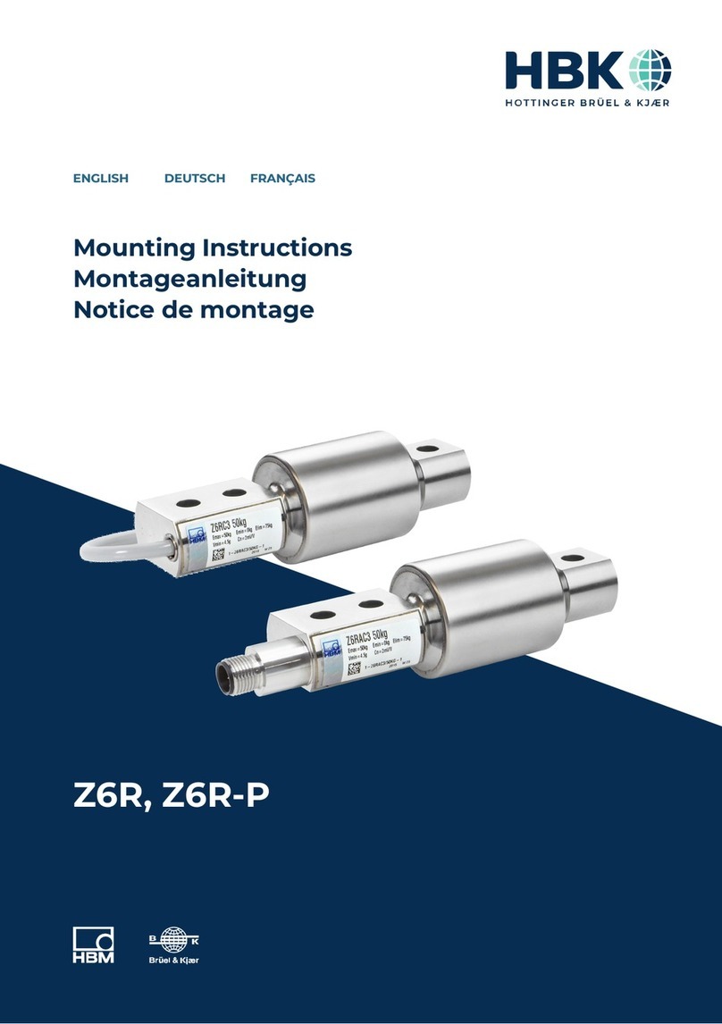
HBK Z7A User manual

Z7A
ENGLISH DEUTSCH FRANÇAIS
Mounting Instructions
Montageanleitung
Notice de montage

Hottinger Brüel & Kjaer GmbH
Im Tiefen See 45
D-64293 Darmstadt
Tel. +49 6151 803-0
Fax +49 6151 803-9100
www.hbkworld.com
Mat.: 7-0101.0019
DVS: A01847 02 Y00 01
03.2022
EHottinger Brüel & Kjaer GmbH
Subject to modifications.
All product descriptions are for general information
only. They are not to be understood as a guarantee of
quality or durability.
Änderungen vorbehalten.
Alle Angaben beschreiben unsere Produkte in allge
meiner Form. Sie stellen keine Beschaffenheits- oder
Haltbarkeitsgarantie dar.
Sous réserve de modifications.
Les caractéristiques indiquées ne décrivent nos
produits que sous une forme générale. Elles
n'impliquent aucune garantie de qualité ou de
durabilité.

Z7A
ENGLISH DEUTSCH FRANÇAIS
Mounting Instructions

Z7A
TABLE OF CONTENTS
2
TABLE OF CONTENTS
1 Safety instructions 3................................................
2 Markings used 5....................................................
2.1 The markings used in this document 5.................................
2.2 Symbols on the product 5............................................
3 Notes on Mounting 6................................................
4 Load introduction 7.................................................
5 Connection 8.......................................................
5.1 Parallel connection 8................................................
5.2 Transducer connected in the four‐wire technique 9.......................
5.3 Cable extension 9...................................................
6 Specifications 10....................................................
7 Dimensions Z7A (in mm; 1 mm = 0.03937 inches) 12.....................
8 Accessories 13......................................................

3
Z7A
SAFETY INSTRUCTIONS
1 SAFETY INSTRUCTIONS
In cases where a breakage may cause injury to persons or damage to equipment, the
user must take appropriate safety measures (such as fall protection, overload protection,
etc.). Safe and trouble‐free operation of the load cells requires proper transportation,
correct storage, assembly and mounting as well as careful operation and maintenance.
It is essential to comply with the relevant accident prevention regulations. In particular
you should take into account the limit loads quoted in the specifications.
Use in accordance with the regulations
Z7A/... type load cells have been designed for weighing applications. Use for any addi
tional purpose shall be deemed to be not in accordance with the regulations.
To ensure safe operation, the load cells should only be used as described in the Mounting
Instructions. It is also essential to observe the appropriate legal and safety regulations
for the application concerned during use. The same applies to the use of accessories.
The Z7A/... load cells can be used as machine components (e.g. with tank weighing).
Please note in these cases that, in order to provide a high sensitivity, the load cells have
not been designed with the safety factors normally applied in machine design. The load
cell is not a safety element within the meaning of its use in accordance with the regula
tions. The measuring signal processing electronics has to be designed in such a way that
with a measuring signal failure no damages can occur.
General dangers due to non‐observance of the safety instructions
The Z7A/... load cells correspond to the state of the art and are fail‐safe. The load cells
can give rise to residual dangers if they are inappropriately installed and operated by un
trained personnel.
Everyone involved with the installation, commissioning, maintenance or repair of a load
cell must have read and understood the Mounting Instructions and in particular the tech
nical safety instructions.
Residual dangers
The scope of supply and performance of the load cells covers only a small part of weigh
ing technology. In addition, equipment planners, installers and operators should plan, im
plement and respond to the safety engineering considerations of weighing technology in
such a way as to minimize residual dangers. Prevailing regulations must be complied
with at all times. There must be reference to the residual dangers connected with weigh
ing technology.

Z7A
SAFETY INSTRUCTIONS
4
Environmental conditions
In the context of your application, please note that acids and all materials which release
(chlorine) ions will attack all grades of stainless steel and their welding seams. This may
result in corrosion which can lead to the failure of the load cell. In such cases the opera
tor must take appropriate safety measures.
Prohibition of own conversions and modifications
The load cells must not be modified from the design or safety engineering point of view
except with our express agreement. Any modification shall exclude all liability on our part
for any damage resulting therefrom.
Qualified personnel
These load cells are only to be installed by qualified personnel strictly in accordance with
the specifications and with the safety rules and regulations which follow. It is also essen
tial to observe the appropriate legal and safety regulations for the application concerned.
The same applies to the use of accessories.
Qualified personnel means persons entrusted with the installation, fitting, commissioning
and operation of the product who possess the appropriate qualifications for their func
tion.
Accident prevention
Although the specified maximum capacity in the destructive range is several times the
full scale value, the relevant accident prevention regulations from the trade associations
must be complied with. Take into consideration the values specified in particular in
chapter 4:
Slimit loads,
Smax. longitudinal forces,
Smax. transverse forces.

5
Z7A
MARKINGS USED
2 MARKINGS USED
2.1 The markings used in this document
Important instructions for your safety are specifically identified. It is essential to follow
these instructions in order to prevent accidents and damage to property.
Symbol Significance
Notice This marking draws your attention to a situation in
which failure to comply with safety requirements can
lead to damage to property.
Important
This marking draws your attention to important in
formation about the product or about handling the
product.
Tip
This marking indicates application tips or other
information that is useful to you.
Information
This marking draws your attention to information
about the product or about handling the product.
Emphasis
See …
Italics are used to emphasize and highlight text and
identify references to sections, diagrams, or external
documents and files.
2.2 Symbols on the product
CE mark
The CE mark enables the manufacturer to guarantee that the
product complies with the requirements of the relevant EC direc
tives (the declaration of conformity is available at
http://www.hbm.com/HBMdoc
).

Z7A
NOTES ON MOUNTING
6
3 NOTES ON MOUNTING
The following must be considered during the assembly of load cells:
SThe load cell must be handled with care.
SDo not overload the load cell, not even for a short time, for example, by impact forces
during mounting or unevenly distributed supporting forces.
SThe load cell seating must be horizontal, flat over the whole surface and, like the load
cell base, absolutely clean.
SThe fundament must be unyielding in relation to the expected loads.
SDust, dirt and other particles are not to accumulate such that they affect the load cell's
mobility and thus falsify the measured value.
SEvery load cell should be shunted by a stranded copper cable (approx. 16 mm2, e.g.
EEK... from HBM) during or immediately after installation to prevent any welding cur
rents from flowing through the load cell.
SIn load cells with an additional outer braided wire over the cable (item no. K-Z7A_ with
options 6R or 12R), this cable is only used for protection against increased mechani
cal stress (e.g. damage caused by gnawing rodents). To avoid accidental energiza
tion, the outer braided wire must be connected to potential equalization at least once.
This outer braid is not used to shield the load cell. The inner braid of the load cell ca
ble is used for shielding.
Notice
Never load the transducers against the indicated load direction (see arrow on the load
introduction side). This results in measuring errors and can damage the fixing bolts. With
the correct load direction and electrical connection, the output signal of the load cells is
positive.
The load cells are fixed at the mounting bores like a cantilever beam, the load is applied
at the other end. For the recommended screws and tightening torques refer to the table
below:
Max. capacity Thread Min. property
class
Tightening torque1)
Frict. coeff. μ= 0.125
0.5...2 t 2 x M12 10.9 115 Nm
5 t 2 x M20 10.9 560 Nm
10 t 2 x M24 10.9 970 Nm
1) Recommendedvalue for the stated property class. For screw dimensioning please refer to the
appropriate information given by the screw manufacturers.

7
Z7A
LOAD INTRODUCTION
4 LOAD INTRODUCTION
Loads should be introduced as closely as possible in the direction of measurement. Tor
sional moments, off‐center loads and transverse or lateral forces cause measurement
errors and may damage the load cell. These adverse influences must be avoided, e.g. by
using stay rods or guide rolls. These elements must not absorb any load or force compo
nents in the direction of measurement.
HBM offers different load‐introduction components suiting various mounting situations in
order to minimize the adverse effects due to load introduction:
SZEL Rubber‐metal bearing
SZPL Pendulum bearing
SEPO3R Thrust piece
SZL Load button insert
SZK Spherical cap

Z7A
CONNECTION
8
5 CONNECTION
Load cells with a strain gage measuring system can be connected to:
Scarrier‐frequency measuring amplifiers, or
SDC measuring amplifiers suitable for strain gage measuring systems.
The load cells are connected using the six‐wire circuit. The wiring assignment is shown in
the following diagram.
(white)
(black)
(grey)
Excitation (+)
(green)
(red)
(Wire strand)
Excitation (-)
Sense (-)
Signal (+)
(blue)
Sense (+)
Signal (-)
Shield,
connected to housing
Electric and magnetic fields often induce interference voltages in the measurement cir
cuit. Therefore:
Suse shielded, low‐capacitance measurement cables only (HBM cables fulfill these
conditions),
Sdo not route the measurement cables parallel to power lines and control circuits. If
this is not possible, protect the measurement cable with steel conduit for example.
Savoid stray fields from transformers, motors and contact switches.
5.1 Parallel connection
Load cells can be wired in parallel by joining the load cell cable core ends of the same
color. In this case, HBM provides junction boxes of the VKK... series. The output signal is
then the average of the individual output signals.
Important
Overloading of an individual load cell cannot then be detected from the output signal.

9
Z7A
CONNECTION
5.2 Transducer connected in the four‐wire technique
Upon connection to amplifiers using the four‐wire circuit, the cores bl (blue) and gn
(green) should be connected, as should bk (black) and gr (gray). The following deviations
occur in the case of cable of original length (6 m): Sensitivity -0.4 % and temperature co
efficient -0.02 %/10 K.
5.3 Cable extension
Extension cables must be shielded and of low capacitance. We recommend the use of
HBM cables, which satisfy these requirements.
HBM extension cables, 6 wires:
SKAB8/00‐2/2/2 (sold by the meter, order‐no. 4‐3301.0071 = grey or
4‐3301.0082 = blue)
SCABA1 (cable roll, order‐no. CABA1/20 = 20 m or CABA1/100 = 100 m in length)
With cable extensions it is important to ensure a good connection with minimum contact
resistance and good insulation.
When using the six‐wire circuit, the effects of resistance changes in the extension cable
are compensated. If you extend the cable using the four‐wire circuit, the sensitivity devi
ation can be eliminated by adjusting the amplifier. However, temperature effects can only
be compensated when operating with the six‐wire circuit.
Route the load cell connection cable so that any condensed water or dampness forming
on the cable can drip off. It must not be able to reach the load cell. In addition ensure that
no dampness can penetrate the open ends of the cable.
Load cell
Humidity
Connection cable

Z7A
SPECIFICATIONS
10
6 SPECIFICATIONS
Type Z7A
Accuracy class according to OIML R 60
Maximum number of load cell verification
intervals (nLC)
D1
1000
C3
3000
Max. capacity (Emax)t0.5; 1; 2; 5; 10 2; 5; 10
Min. load cell verificat. interval (vmin)% of
Emax
0.0357 0.0100
Sensivity (Cn)mV/V 2
Sensivity tolerance % ±0.1000 ±0.0500
Temperat. effect on sensivity (TKC)1) % of
Cn/10 K
±0.0350 ±0.0117
Temperat. effect on zero signal (TK0)±0.0500 ±0.0140
Hysteresis error (dhy)1)
% of Cn
±0.0500 ±0.0170
Non‐linearity (dlin)1) ±0.1000 ±0.0333
Creep (dcr) in 30 min. ±0.0735 ±0.0167
Input resistance (RLC)
Ω
350
Output resistance (RO) 356±0.2 356±0.12
Reference excitation volt. range (Uref)V0.5...12
Max. excitation voltage (BU)18
Nominal temperature range (BT)
°C [°F]
-10...+40 [+14...104]
Operating temperature range (Btu)-30...+70 [-22...158]
Storage temperature range (Btl)-50...+85 [-58...185]
Safe load limit (EL)% of
Emax
150
Breaking load (Ed)300
Max. capacity (Emax)t 0.5 1 2 5 10
Relative static lateral force
limit (Elq)2)
% of
Emax
100 50 25
(100)2) 15
(100)2) 18
(100)2)
Permissible dynamic load
(Fsrel) (vibration amplitude acc.
to DIN 50100)
70

11
Z7A
SPECIFICATIONS
Max. capacity (Emax)105210.5t
Nominal displacement (snom),
approx.
mm 0.25 0.30 0.35 0.45 0.70
Weight (G), approx. kg 2.3 5 8
Degree of protection,
acc. to IEC529
IP 67
Material
Measuring body
Cable gland
Cable sheath
Steel, galvanized nickel
Stainless steel3), VitonR
PVC
1) The data for linearity error (dlin) hyseresis (dhy) and temperature effect TKc) on sensitivity are typical
values. The sum of these data meets the requirements of OIML R60
2) The values indicated in parentheses refer to mounting conditions, with which the transducer foot is
prevented by stops from a movement. Here, major effects of errors have to be expected.
3) Acc. to EN 10088-1

Z7A
DIMENSIONS Z7A
12
7 DIMENSIONS Z7A (IN MM; 1 MM = 0.03937 INCHES)
øL
øM
NH
K2
D
A
B
Cable: 6 cores screened
5.4 - 6 m long
E
FG
K1
C
J
Max.
capac.
t
L+0.2 MH11 J B H N A D F G E C K1 K2 M1)
NVm
0.5; 1 30.2 17.5 13.4 47.6 11.1 11.9 203.2 101 98.3 63.5 19.1 36.5 10.6 29 135
230.2 17.5 13.4 47.6 11.1 11.9 203.2 102 98.3 63.5 19.1 36.5 10.6 29 135
541.3 25.5 22.5 70 22.2 15.9 235 118 123.7 66.5 20.6 47.6 16 46 660
10 51 32 27 82.6 19.1 20.7 279.4 140 139.7 82.6 25.4 60.3 21 51 1150
1) Tightening torque for screws with min. property class 10.9 (with friction coefficient μ = 0.16)

13
Z7A
ACCESSORIES
8 ACCESSORIES
ZEL Rubber‐metal bearing
R
B
ZEL
Z
a
X
Y
e
L
P
T
Max.
capac.
t
ZEL
Rubber-
metal
bearing
B L P R T X Y Z a e FR1)
N
smax2)
mm
mm
0.5...2 Z17/2t/
ZEL
76.3 180.9 70 100 9 120 60 10 112 +1.5
‐1.7 80 400 4.5
5Z17/5t/
ZEL
93 210.8 70 125 11 150 100 10 147+1.2
‐2.0 100 620 8
10 HLCB/
10t/ZEL
114.1 247.7 90 175 13 200 100 12 176 +1.8
‐2.0 130 810 9.5
1) FRRestoring force in N for s = 1 mm
2) smax Max. lateral displacement at max. capacity

Z7A
ACCESSORIES
14
Pendulum bearing ZPL
when the ZPL is
delivered two dust
protection rings
are also included
ZPL
max. deviation 35
M
D1
∅U
∅O
H
E
F1
T
∅C1
∅C
Max.
capac.
t
t
ZPL
Pendulum
bearing
C+0.
2
C1‐0.
1
D1E F1H M O T UD10
h9
FR1)
% of
load
smax2)
mm
0.5...2 Z17/2t/Z
PL
30.2 30 60 22 14 130
0.5
M10 46 8 30 2 7.5
5Z17/5t/Z
PL
41.3 41.1 73 26 16 169
0.5
M10 48 8 30 1.5 6.9
10 Z17/10t/Z
PL
51 50.8 82 32 21 196
0.5
M12 58 10 40 1.8 9.3
1) FRRestoring force in N for s = 1 mm
2) smax.Max. lateral displacement at max. capacity

15
Z7A
ACCESSORIES
EPO3R Thrust piece
Max.
capac.
(t)
EPO3R
Thrust piece
C-0.1 D E H3 H4 N O P Q
0.5...2 EPO3R/5t 37.8 21 16 58.7 74.7 12 89 70 9
5EPO3R/5t 37.8 21 16 81.1 79.1 12 89 70 9
10 EPO3R/20t 47.8 28 20 95.9 115.9 14 114 90 13
ZL Load button insert ZK Spherical cap
3
Spheric R1Spheric R2
Thread hole not
with capacities 2 t
Max.
capac.
(t)
ZL
Load but
ton insert
ZK
Spherical
cap
A C1-0.
1
C2C3C4C5F F1F2F3R1R2 U
0.5...2 Z17/2t/
ZL
Z17/2t/Z
K
17.5 30 15 13 28 29 10 12 27.5 4.5 60 38 25−0.05
−0.1
5Z17/5t/
ZL
Z17/5t/Z
K
25.5 41.1 23 21 39 40 12.3 16 31.5 4.5 60 57 25
−0.05
−0.1
10 Z17/10t/
ZL
Z17/10t/
ZK
32 50.8 28 25 47 50 15 21 39.5 5.5 160 70 25 −0.05
−0.1

Z7A
ACCESSORIES
16

Z7A
ENGLISH DEUTSCH FRANÇAIS
Montageanleitung

Z7A
INHALTSVERZEICHNIS
2
INHALTSVERZEICHNIS
1 Sicherheitshinweise 3...............................................
2 Verwendete Kennzeichnungen 5......................................
2.1 In dieser Anleitung verwendete Kennzeichnungen 5......................
2.2 Auf dem Gerät angebrachte Symbole 5.................................
3 Montagehinweise 6.................................................
4 Lasteinleitung 7....................................................
5 Anschließen 8......................................................
5.1 Parallelschaltung 8..................................................
5.2 Anschluss in Vierleiter‐Technik 9......................................
5.3 Kabelverlängerungen 9..............................................
6 Technische Daten 10.................................................
7 Abmessungen Z7A (mm) 12...........................................
8 Zubehör 13.........................................................
Table of contents
Languages:
Other HBK Measuring Instrument manuals
