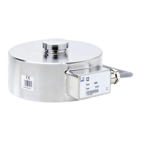
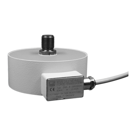
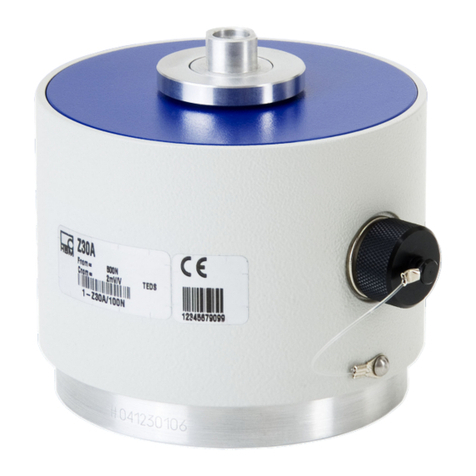
HBK C5 User manual

C5
ENGLISH DEUTSCH FRANÇAIS
Mounting Instructions
Montageanleitung
Notice de montage

Hottinger Brüel & Kjaer GmbH
Im Tiefen See 45
D-64293 Darmstadt
Tel. +49 6151 803-0
Fax +49 6151 803-9100
www.hbkworld.com
Mat.: 7-0111.0019
DVS: A05804 01 YC0 00
01.2022
EHottinger Brüel & Kjaer GmbH
Subject to modifications.
All product descriptions are for general information
only. They are not to be understood as a guarantee of
quality or durability.
Änderungen vorbehalten.
Alle Angaben beschreiben unsere Produkte in allge
meiner Form. Sie stellen keine Beschaffenheits- oder
Haltbarkeitsgarantie dar.
Sous réserve de modifications.
Les caractéristiques indiquées ne décrivent nos
produits que sous une forme générale. Elles
n'impliquent aucune garantie de qualité ou de
durabilité.
保留变更的权利。
所有信息是对我品的般性描。在性能或者
耐性方它并提保证。

C5
ENGLISH DEUTSCH FRANÇAIS
Mounting Instructions

C5
TABLE OF CONTENTS
2
TABLE OF CONTENTS
1 Safety Instructions 3................................................
2 Markings used 6....................................................
2.1 Markings used in this document 6.....................................
3 Scope of supply and equipment variants 7.............................
3.1 Scope of supply 7..................................................
3.2 Accessories (not included in the scope of supply) 7......................
3.3 Equipment variants 7................................................
4 General application instructions 9....................................
5 Structure and mode of operation 10....................................
5.1 Force transducer operation 10.........................................
5.2 Strain gage housing 10...............................................
6 Conditions on site 11.................................................
6.1 Ambient temperature 11..............................................
6.2 Moisture and corrosion protection 11...................................
6.3 Deposits 11.........................................................
7 Mechanical installation 12............................................
7.1 Important precautions during installation 12..............................
7.2 General installation guidelines 12.......................................
7.3 Using the C5 with a thrust piece 14.....................................
8 Electrical connection 15..............................................
8.1 Shortening or extending the cable 16....................................
8.2 4-wire connection 16.................................................
8.3 EMC protection 17...................................................
9 TEDS chips transducer identification 18................................
10 Dimensions 19......................................................
11 Mounting dimensions of connection variants 20.........................
12 Specifications 22....................................................
13 Versions and ordering numbers 24.....................................

3
C5
SAFETY INSTRUCTIONS
1 SAFETY INSTRUCTIONS
Intended use
Force transducers in the C5 series are designed solely for measuring static and dynamic
compressive forces within the load limits stated in the specifications. Any other use is
not the intended use. To ensure safe operation, it is essential to comply with the
regulations in the mounting instructions, the safety requirements listed below, and the
data specified in the supplied technical data sheets. It is also essential to observe the
applicable legal and safety regulations for the relevant application.
Force transducers are not intended for use as safety components. Please also refer to
the “Additional safety precautions” section. Proper and safe operation of force
transducers requires proper transportation, correct storage, setup and mounting, and
careful operation.
Load-carrying capacity limits
The information in the technical data sheets must be observed when using the force
transducers. The respective specified maximum loads in particular must never be
exceeded. The values specified in the technical data sheets must not be exceeded:
SForce limits
SLateral force limits
SMaximum eccentricity
SBreaking forces
SPermissible dynamic loads
STemperature limits
SElectrical load limits
Please note that when several force transducers are interconnected, the load/force
distribution is not always uniform.
Use as machine elements
Force transducers can be used as machine elements. When used in this manner, note
that to favor greater sensitivity, force transducers were not designed with the safety
factors usual in mechanical engineering. Please refer here to the "Load-carrying capacity
limits" section and to the specifications.
Accident prevention
The prevailing accident prevention regulations must be taken into account, even though
the nominal (rated) force values in the destructive range are well in excess of the full
scale value.

C5
SAFETY INSTRUCTIONS
4
Additional safety precautions
The force transducers (as passive transducers) cannot execute (safety) shutdowns. This
requires additional components and design measures, for which the installer and
operator of the plant is responsible.
Wherever,in the event of breakage or malfunction of the force transducers, people or
property may be injured, the user must take suitable additional safety precautions which
at least comply with the relevant accident prevention regulations (e.g. automatic
emergency stop, overload protection, catch straps or chains, or other fall protection
devices).
The electronics that processes the measurement signal should be designed so that
failure of the measurement signal cannot lead to secondary failures.
General dangers of failing to follow the safety instructions
Force transducers are state-of-the-art and failsafe. The transducers can be dangerous if
they are mounted, set up or operated improperly, or by untrained personnel. Every person
involved in setting up, starting up, operating or repairing a force transducer must have
read and understood the mounting instructions and in particular the technical safety
instructions. The force transducers can be damaged or destroyed by non-designated use
of the force transducer or by non-compliance with the mounting manual, these safety
instructions or other applicable safety regulations (safety and accident prevention
regulations of the Employers' Liability Insurance Association) when using the force trans
ducers. A force transducer can break, particularly if it is overloaded. The breakage of a
force transducer can cause damage to property or injury to persons in the vicinity of the
force transducer.
If force transducers are not used in accordance with their intended purpose, or if the
safety instructions or the specifications in the mounting instructions are disregarded, the
force transducers may also fail or malfunction, with the result that (due to loads acting on
or monitored by the force transducers) people or property may be injured.
The scope of supply and performance of the transducer covers only a small area of force
measurement technology, as measurements with (resistive) strain gage sensors
presuppose the use of electronic signal processing. Equipment planners, installers and
operators should always plan, implement and respond to the safety engineering
considerations of force measurement technology in such a way as to minimize residual
dangers. Pertinent national and local regulations must be complied with.
Conversions and modifications
The design or safety engineering of the transducer must not be modified without our
express permission. Any modification shall exclude all liability on our part for any
resulting damage.

5
C5
SAFETY INSTRUCTIONS
Maintenance
The force transducers of the C5 series are maintenance free. We recommend having the
force transducer calibrated at regular intervals.
Disposal
In accordance with national and local environmental protection and material recovery and
recycling regulations, old transducers that can no longer be used must be disposed of
separately and not with normal household garbage.
If you require more information about disposal, please contact your local authorities or
the dealer from whom you purchased the product.
Qualified personnel
Qualified personnel means persons entrusted with installing, mounting, starting up and
operating the product who possess the appropriate qualifications for their work.
This includes people who meet at least one of these three requirements:
SAs project personnel, you know and are familiar with the safety concepts of
automation technology.
SAs automation plant operating personnel, you have been instructed how to handle the
machinery. You are familiar with the operation of the equipment and technologies
described in this documentation.
SAs a commissioning or service engineer, you have successfully completed training on
the repair of automation plants. Moreover, you are authorized to start up, ground and
label circuits and equipment in accordance with safety engineering standards.
During use, compliance with the legal and safety requirements for the relevant
application is also essential. The same applies to the use of accessories.
The force transducer may only be used by qualified personnel exclusively in accordance
with the technical data in conjunction with the safety rules and regulations.

C5
MARKINGS USED
6
2 MARKINGS USED
2.1 Markings used in this document
Important instructions for your safety are highlighted. It is essential to follow these
instructions to prevent accidents and damage to property.
Icon Meaning
WARNING This marking warns of a potentially dangerous situa
tion in which failure to comply with safety require
ments could result in death or serious physical injury.
CAUTION This marking warns of a potentially dangerous situa
tion in which failure to comply with safety require
ments could result in slight or moderate physical
injury.
Notice This marking draws your attention to a situation in
which failure to comply with safety requirements
could lead to property damage.
Important This marking draws your attention to important
information about the product or about handling the
product.
Tip This marking indicates tips for use or other
information that is useful to you.
Information This marking draws your attention to information
about the product or about handling the product.
Emphasis
See …
Italics are used to emphasize and highlight text and
identify references to sections of the manual,
diagrams, or external documents and files.
uThis symbol indicates an action step.

7
C5
SCOPE OF SUPPLY AND EQUIPMENT VARIANTS
3 SCOPE OF SUPPLY AND EQUIPMENT VARIANTS
3.1 Scope of supply
SC5 force transducer
SC5 mounting instructions
STest report
3.2 Accessories (not included in the scope of supply)
Connection cable/ground cable Ordering number
Configurable connection cable for connecting the force
transducer to the bridge amplifier
K-CAB-F
Connection cable KAB157-3; IP67 (with bayonet locking); 3 m
long, TPE outer sheath; 6 x 0.25mm²; free ends, shielded, outside
diameter 6.5 mm
1-KAB157-3
Connection cable KAB158-3; IP54 (with screw lock); 3 m long,
TPE outer sheath; 6 x 0.25mm²; free ends, shielded, outside
diameter 6.5 mm
1-KAB158-3
Loose cable socket (bayonet connection) 3-3312.0382
Loose cable socket (screw connection) 3-3312.0354
Ground cable, 400 mm long 1-EEK4
Ground cable, 600 mm long 1-EEK6
Ground cable, 800 mm long 1-EEK8
3.3 Equipment variants
The C5 force transducer always comes supplied with a thrust piece.
The force transducer is available in different versions. The following options are
available:
1. Nominal (rated) force
You can purchase force transducers with nominal (rated) forces between 5 MN and
20 MN. The nominal (rated) force is the force at which the sensor provides the rated out
put specified on the type plate as the output signal.
2. Number of measuring bridges
You can purchase the force transducer with a single bridge (SB), in which case the C5
comes supplied with one measuring bridge. The double-bridge version (DB) is optionally
available. The C5 then comes supplied with two electrically isolated bridge circuits.

C5
SCOPE OF SUPPLY AND EQUIPMENT VARIANTS
8
3. Bending moment bridges
You can purchase the force transducer with or without bending moment bridges (NB). If
you select the bending moment bridges option, the C5 comes with two electrically
isolated bending moment bridges.
The bending moments are recorded at 90 degrees to each other. Please note that no
characteristic value is specified for the bending moment bridges in the test report or in
the optional calibration certificate.
4. Transducer identification
You can purchase the force transducer with transducer identification (“TEDS”). TEDS
(Transducer Electronic Data Sheet) makes it possible to store the transducer data
(characteristic values) in a chip which can be read out by a connected measuring device.
With the double bridge version, or if you have selected optional bending moment bridges,
each measuring bridge is assigned its own TEDS. See also section 9, page 18.
5. Plug protection
On request, we can fit plug protection, consisting of a strong square tube, so that the plug
is protected against mechanical damage.
6. Plug version
The standard version of the force transducer is delivered with a bayonet connector. A
threaded connector can be supplied instead, if required. It is also possible to obtain the
force transducer with a fixed cable.

9
C5
GENERAL APPLICATION INSTRUCTIONS
4 GENERAL APPLICATION INSTRUCTIONS
Force transducers are suitable for measuring compressive forces. They provide highly
accurate static and dynamic force measurements and must therefore be handled very
carefully. Particular care must be taken when transporting and installing the devices.
Dropping or knocking the transducer may cause permanent damage.
The permissible limits for mechanical, thermal and electrical stress are listed in sec
tion 12 “Specifications”, page 22. It is essential to take these limits into account when
planning the measuring setup, during installation and, ultimately, during operation.

C5
STRUCTURE AND MODE OF OPERATION
10
5 STRUCTURE AND MODE OF OPERATION
5.1 Force transducer operation
The measuring body is a steel spring element to which strain gages are applied. The
strain gages for each measuring circuit are installed so that four extend and four shorten
when a force acts on the transducer. Each strain gage changes its ohmic resistance in
proportion to its change in length and so misaligns the Wheatstone bridge. If bridge
excitation voltage is present, the circuit produces an output signal proportional to the
change in resistance and therefore also proportional to the applied force. The SGs are
arranged such that parasitic forces or torques and temperature effects are compensated
as much as possible.
If the bending moment bridges option is selected, the force transducer is equipped with
two additional measuring bridges. These measuring bridges are installed in such a way
that force acting in the measuring direction is largely compensated, but acting bending
moments (such as due to eccentric force action) lead to an output signal.
5.2 Strain gage housing
To protect the strain gages, the column-type force transducers have a housing which is
screwed to the force transducer and protects the strain gages from external influences.
The housing must not be removed or damaged.

11
C5
CONDITIONS ON SITE
6 CONDITIONS ON SITE
Protect the transducer from weather conditions such as rain, snow, ice, and salt water.
6.1 Ambient temperature
The effects of temperature on the zero signal and rated output are compensated. To
obtain optimum measurement results, comply with the nominal (rated) temperature
range. The strain gages are designed and arranged to ensure a high insensitivity to
temperature gradients. Despite this, temperatures that are constant and, ideally, change
slowly have a favorable effect on accuracy. A radiation shield and thermal insulation on
all sides provide noticeable improvements,but must not form a force shunt.
6.2 Moisture and corrosion protection
Regardless of the choice of electrical connection, the sensors achieve IP 54 protection
according to DIN EN 60529 (splash-proof).
We recommend protecting the sensor from long-term exposure to moisture and weather
conditions.
6.3 Deposits
Dust, dirt and other foreign matter must not be allowed to accumulate to such an extent
that some of the measuring force is diverted, invalidating the measured value (force
shunt).

C5
MECHANICAL INSTALLATION
12
7 MECHANICAL INSTALLATION
7.1 Important precautions during installation
SHandle the transducer with care.
SNote the requirements for the force application parts stated in the following sections
of this manual.
SWelding currents must not be allowed to flow over the transducer. If there is a risk
that this might happen, you must use a suitable low-ohm connection to electrically
bypass the transducer. HBM provides the highly flexible EEK ground cable for this
purpose, for example, that is screwed on above and below the transducer.
SMake sure that the transducer cannot be overloaded.
WARNING
There is a danger of the transducer breaking if it is overloaded. This could endanger the
operating personnel of the equipment in which the transducer is installed.
Implement appropriate safety measures to avoid a force overshoot or to protect against
resulting dangers. The maximum possible mechanical stresses, especially the breaking
force,are noted in the specifications.
During installation and operation of the transducer, observe the maximum parasitic forces
- lateral forces, bending moments and torques, see technical data - and the maximum
permissible load capacity of the force application parts being used.
7.2 General installation guidelines
The forces to be measured must act on the transducer as accurately as possible in the
direction of measurement. Eccentric loads,resulting bending moments and lateral forces
can lead to measurement errors and destroy the transducer if the limit values are
exceeded.
Customers' constructional elements must meet the following conditions..
SThey must be sufficiently rigid so that they do not bend even under load
SThey must have sufficient hardness (40 HRC minimum)
SThey must be free of paint or other coatings
SThe upper and lower load application points must be parallel to each other

13
C5
MECHANICAL INSTALLATION
Fex Fnom
Fq
Mb
Fnom Force in direction of measurement
Fex Force parallel to direction of measurement, but outside center of
force transducer
MbBending moment
FqForce perpendicular to direction of measurement
The C5 is a high-quality reference transducer. It is advisable to always have the sensor
calibrated with the attachments with which it is planned to use the sensor.
You can place the C5 directly on a suitable substructure. The force transducer measures
static and dynamic compressive forces, and can be used at full oscillation width (peak-to-
peak).
Load is applied via the spherical load button on top of the force transducer. We
recommend using the supplied thrust piece to guarantee ideal force application. The
thrust piece has a suitable surface finish, and is placed on the crowned load button.
If you want to do without a thrust piece, please note that the surface of the structural
component that applies the force to the convex load application part must be ground and
have a minimum hardness of 40 HRC.

C5
MECHANICAL INSTALLATION
14
The substructure must be capable of absorbing the force to be measured. Remember
that the rigidity of the overall system depends on the stiffness of the force application
part and the substructure. Please also note that the substructure must ensure that force
is always applied to the transducer vertically, meaning there must be no inclination, even
under full load.
7.3 Using the C5 with a thrust piece
Thrust pieces prevent torsional moments being applied, can adjust slight misalignments,
and make sure that the compressive forces are applied centrally.
The transducer has a load button with a crowned load application surface. The thrust
piece is simply placed onto the load button and the sensor is placed on a surface that is
sufficiently hard and flat.
The C5 force transducer comes supplied with a suitable thrust piece as standard. All
thrust pieces offered by HBK comply with the recommendations of ISO 376.

15
C5
ELECTRICAL CONNECTION
8 ELECTRICAL CONNECTION
Signal conditioners designed for strain gage measuring systems can be used for
conditioning measurement signals. Both carrier frequency-and DC amplifiers can be
connected.
C5 force transducers are delivered in a six-wire configuration and are available with the
following electrical connections:
SBayonet connector: plug-compatible with the MIL-C-26482 series 1 connection
(PT02E10-6P); IP54 (standard version)
SThreaded connector: plug-compatible with the MIL-C-26482 series 1 connection
(PC02E10-6P); IP54
SCable connection: With fixed 6-wire cable; IP54
wh (white)
bk (black)
rd (red)
bu (blue)
gn (green)
gy (gray)
Shield
Measurement signal (+)
Excitation voltage (+)
Sense lead (-)
Sense lead (+)
Excitation voltage (-)
Measurement signal (-)
Cable shield,
connected to housing
B
D
C
A
F
E
Device plug pin assignment Cable assignment
AF
B
C
E
D
Fig. 8.1 6-wire connection

C5
ELECTRICAL CONNECTION
16
Threaded connector Bayonet connector
Fig. 8.2 Pin assignment for HBM cables
With this cable assignment, the output voltage on the amplifier is positive in the pressure
direction when the transducer is loaded.
The cable shield is connected to the transducer housing. This produces a Faraday cage
which covers the sensor, the cable and – provided it is correctly wired – the connector to
the signal conditioner, therefore ensuring optimum reliability even in the critical EMC
environment.
Only use plugs that meet EMC guidelines. The shielding must be fitted flat all over the
surface. With other connection techniques, an EMC-proof shield must be provided in the
stranded wire area and this shielding should also be connected extensively (also see
HBM Greenline Information).
8.1 Shortening or extending the cable
We cannot recommend extending the connection cable. HBK offers cables in various
lengths (also with fitted plug for sensor and amplifier).
8.2 4-wire connection
If you connect 6-wire transducers to 4-wire amplifiers, you must connect the transducer
sense leads to the corresponding excitation voltage leads: Marking (+) with (+) and
marking (-) with (-), see Fig. 8.1. This measure reduces the cable resistance of the
excitation voltage leads, among other effects. If you use an amplifier with a 4-wire
configuration, the output signal and temperature dependence of the output signal (TCS)
depend on the length of the cable and the temperature. If you use the 4-wire
configuration described above, this will result in slightly higher measurement errors. An
amplifier system using the 6-wire configuration can perfectly compensate for these
effects.
If you are using the sensor with a 4-wire configuration, it is essential to consider this in
the calibration.

17
C5
ELECTRICAL CONNECTION
8.3 EMC protection
Electrical and magnetic fields can often induce interference voltages in the measuring
circuit. Therefore please note the following:
SUse only shielded, low-capacitance measurement cables (HBM cables fulfill both
conditions).
SDo not route the measurement cables parallel to power lines and control circuits. If
this cannot be avoided, protect the measurement cable with steel conduits, for
example.
SAvoid stray fields from transformers, motors and contact switches.
SConnect all the devices in the measurement chain to the same protective conductor.
SAlways fit the cable shield all over the surface of the connector housing.

C5
TEDS CHIPS TRANSDUCER IDENTIFICATION
18
9 TEDS CHIPS TRANSDUCER IDENTIFICATION
A TEDS (Transducer Electronic Data Sheet) chip allows you to store the rated outputs of a
sensor in a chip in accordance with IEEE 1451.4. The C5 can be delivered with TEDS chip,
which is then fitted in the transducer housing, connected and supplied with data by HBK
before delivery.
The force transducer is always delivered with a test record.
If the sensor is ordered from HBK without additional calibration, the results of the test
report will be stored in the TEDS chip. If an additional DAkkS calibration is ordered, the
results of the calibration will be stored in the TEDS chip.
The chip content can be edited and modified with suitable hardware and software. This
can be achieved with HBK’s Quantum Assistant or DAQ software, for instance. Please pay
attention to the operating manuals of these products.
Information
Please note that no characteristic values are stored for any bending moment bridges that
may be ordered.
This manual suits for next models
4
Table of contents
Languages:
Other HBK Measuring Instrument manuals
Popular Measuring Instrument manuals by other brands
Netafim
Netafim M Series Installation, operation and maintenance guide

Extech Instruments
Extech Instruments MA3110 user manual

ThermoWorks
ThermoWorks PTR operating instructions
netvox
netvox R718E user manual
ICM Controls
ICM Controls ICM493-60A Installation, operation & application guide
Bosch
Bosch Professional GLM 50-27 CG Original instructions
GHM
GHM GREISINGER GIA 20 EB Mounting and operating manual
TDE Instruments
TDE Instruments Digalox DPM72-MPPV-USB instruction manual
Tektronix
Tektronix WVR7000 Series Quick start user manual
Vishay
Vishay P3 instruction manual
HP
HP 8690B Operating and service manual

Powerfix
Powerfix Z22855 Operation and safety notes
