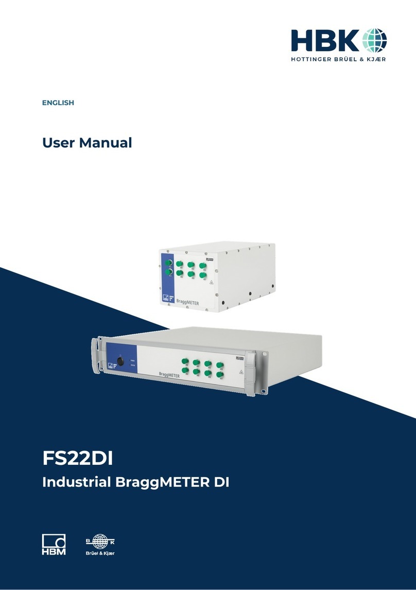
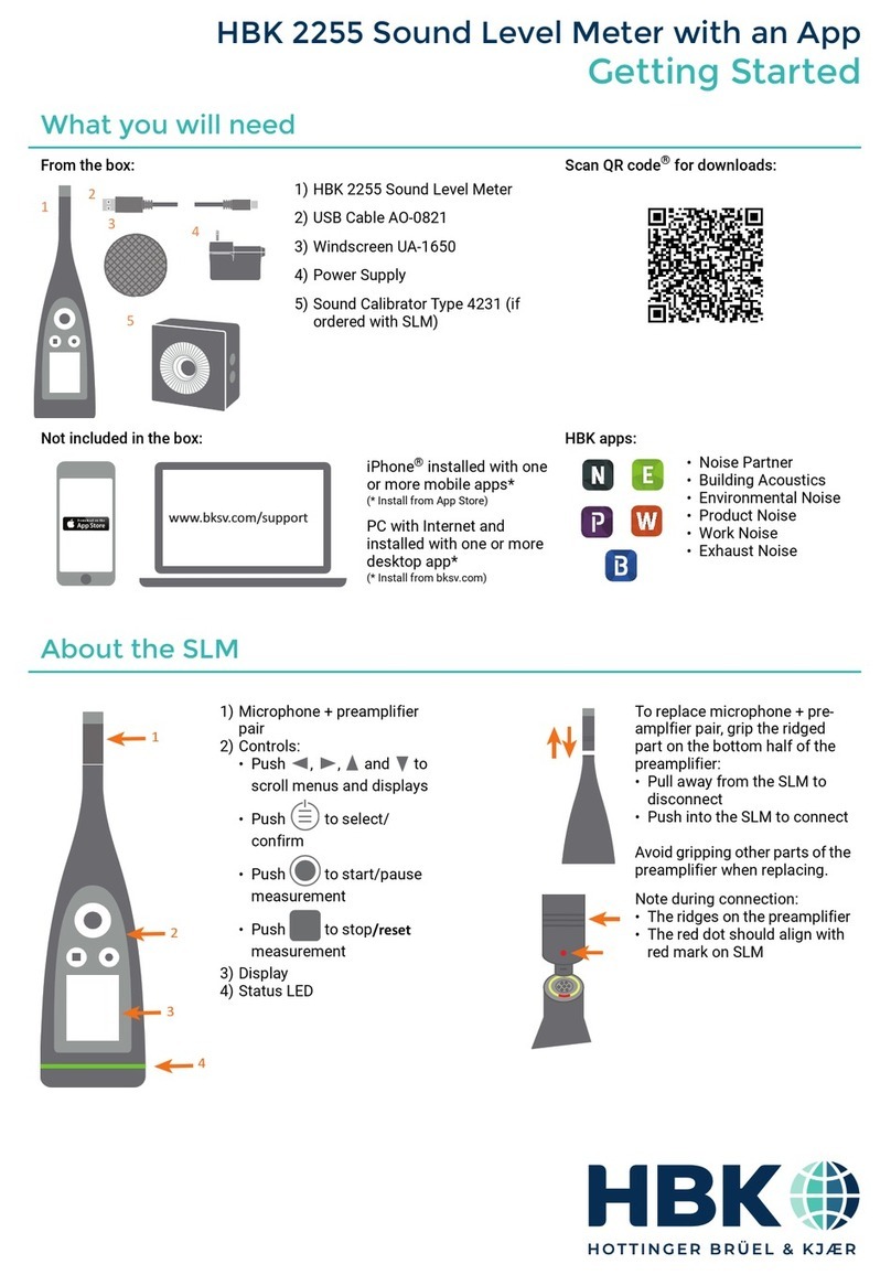
HBK FS22DI User manual

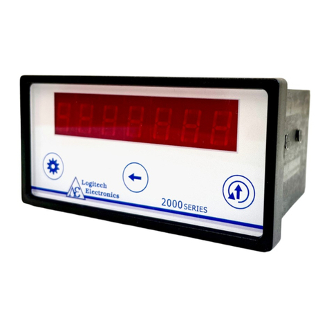
FS22DI
Industrial BraggMETER DI
ENGLISH
Quick Start Guide

Hottinger Brüel & Kjaer GmbH
Im Tiefen See 45
D-64293 Darmstadt
Tel. +49 6151 803-0
Fax +49 6151 803-9100
www.hbkworld.com
HBK FiberSensing, S.A.
Rua Vasconcelos Costa, 277
4470-640 Maia
Portugal
Tel. +351 229 613 010
Fax +351 229 613 020
www.hbm.com/fs
Mat.: 7-2002.4609
DVS: A04609 04 E00 00
02.2022
Interrogator version: v2.0
SW version: v1.8
EHottinger Brüel & Kjaer GmbH
Subject to modifications.
All product descriptions are for general information
only. They are not to be understood as a guarantee of
quality or durability.

3
FS22DI
TABLE OF CONTENTS
TABLE OF CONTENTS
1 Introduction 4......................................................
2 Interrogator Setup 6................................................
2.1 Buttons and Connectors 6............................................
2.1.1 Standard Format 6..................................................
2.1.2 Rack Mountable Format 6............................................
2.2 Turn On 7..........................................................
2.2.1 Power 7...........................................................
2.2.2 Ethernet 8.........................................................
2.2.3 Optical 9...........................................................
2.3 Turn Off 9.........................................................
3 Remote Communications 10..........................................
4 BraggMONITOR DI Software 11........................................
4.1 Installation 11.......................................................
4.2 Graphical User Interface 11............................................
4.2.1 Connect to the Interrogator 11.........................................
4.2.2 Configure Measurements 12...........................................
4.2.3 Set the Configuration 13..............................................
4.2.4 Start Acquisition 14..................................................

FS22DI
INTRODUCTION
4
1 INTRODUCTION
This document is a quick start guide for operating the FS22 - Industrial BraggMETER DI
interrogator from HBK FiberSensing.
For more details please refer to the full user manual provided with the equipment. This
document is also available for download on our website.
This document applies to the following equipment:
FS22 - Industrial BraggMETER DI
Interrogator Characteristics Material Number
Acq.
Rate Enclosure Connectors Configurable Item Standard Item
Dynamic (up to 1000S/s)
Standard
1FC/APC K-FS22-01-500-120 -
SC/APC K-FS22-03-500-120 -
4FC/APC K-FS22-01-500-420 1-FS22DI-ST/4CH
SC/APC K-FS22-03-500-420 -
8FC/APC K-FS22-01-500-820 1-FS22DI-ST/8CH
SC/APC K-FS22-03-500-820 -
Rack-
Mountable
1FC/APC K-FS22-11-500-120 -
SC/APC K-FS22-13-500-120 -
4FC/APC K-FS22-11-500-420 -
SC/APC K-FS22-13-500-420 -
8FC/APC K-FS22-11-500-820 -
SC/APC K-FS22-13-500-820 -

5
FS22DI
INTRODUCTION
The FS22 - Industrial BraggMETER DI set includes:
Standard format Rack-mountable format
- Interrogator
- AC-DC power supply unit 24V
- Ethernet cable (L~2m)
- Mounting blocks with M6 screws
- Connector protection caps
- Mounting hole protection caps
- Quick start guide
- Digital support material
- Calibration certificate
- Interrogator
- Power cord (Type F plug)
- Ethernet cable (L~2m)
- Connector protection caps
- Quick start guide
- Digital support material
- Calibration certificate

FS22DI
INTERROGATOR SETUP
6
2 INTERROGATOR SETUP
2.1 Buttons and Connectors
2.1.1 Standard Format
The FS22 - Industrial BraggMETER DI on its Standard format has the following buttons
and connectors:
Front view Back view
Fig. 2.1
The connectors and buttons in Fig. 2.1 are:
1Optical Output Connectors
2ON/OFF Button
3Power Connector
4Ethernet Connector
5POWER and STATUS LEDs
2.1.2 Rack Mountable Format
The FS22 - Industrial BraggMETER DI on its Rack-Mountable format has the following
buttons and connectors:

7
FS22DI
INTERROGATOR SETUP
Front view
Back view
Fig. 2.2
The connectors and buttons in Fig. 2.2 are:
1ON/OFF Button
2POWER and STATUS LEDs
3Optical Output Connectors
4Power Connector
5Electric fuse
6Safety Power Button
7Fans
8Ethernet Connector
2.2 Turn On
2.2.1 Power
For the Standard interrogator connect the provided power adapter to a 100-240 V power
line and the adapter to the interrogator’s power connector. Alternatively, connect the
interrogator directly to an 11-36 VDC power supply.
For the Rack-Mountable format connect the provided power cable to a 100-240 V power
line and to the interrogator’s power connector. Then, switch the safety power button ON.
Notice
Powering above the specified limits will damage the equipment. For the Rack-mountable
version there is a fuse protection that can be replaced. Please refer to the full user manual
for details.

FS22DI
INTERROGATOR SETUP
8
The Power LED will acknowledge the power supply by turning green for 2 seconds
(Fig. 2.3):
Power LED ON
2s
Fig. 2.3
Start the interrogator by pressing the “ON/OFF” button.
The Status LED will start blinking with the following order and meaning:
Status LED
Blinking 2 Hz
Status LED
Blinking 1 Hz
Status LED
On
Status LED
Blinking 2 Hz
Status LED
Blinking 1 Hz
Status LED
Blinking 5 Hz
(initialization issues)
CorrectWrong
ON(0s) ~10s >30s <60s ?s
Status LED
Blinking 5 Hz
(measurement issues)
Fig. 2.4
Please note that the durations stated in Fig. 2.4 are merely indicative and may vary
depending, for example, on the sampling rate of the interrogator.
Important
In case the interrogator does not start correctly, contact HBK FiberSensing for technical
support.
2.2.2 Ethernet
Connect the provided Ethernet cable, or any other cross over cable, from the interrogator
to your PC network.
To communicate with the interrogator using a computer both elements should be config
ured in the same subnet:

9
FS22DI
INTERROGATOR SETUP
SSet the TCP properties of the computer as follows:
-IP address: 10.0.0.xxx (where xxx should not be 150: the default IP of the FS22DI is
10.0.0.150)
-Subnet mask: 255.0.0.0
STest the connection:
-Launch a command line (e.g. Start →Run →type “cmd”, in Windows environment)
-Type and execute the following command: “ping 10.0.0.150”
-On a successful connection the response should be similar to: “Reply from
10.0.0.150: bytes=
32 time<1ms TTL=60”.
Important
The interrogator can be synchronized to other devices using NTP. For further details refer
to the full user manual of the interrogator.
2.2.3 Optical
The FS22 - Industrial BraggMETER DI can be purchased either with FC/APC or SC/APC
connectors. Select the appropriate connector type and adapter, if needed, to connect the
Fiber Bragg Grating (FBG) sensors to the interrogator.
Attention should be paid to the cleaning of the optical connector(s). A dirty connector can
compromise measurements.
2.3 Turn Off
To turn off the interrogator, the “ON/OFF” button should be pressed between 2 s to 6 s.
The power LED will start blinking acknowledging the shutdown.
Power LED blinking at 1 Hz
Fig. 2.5
Important
Pressing the power button for more than 6 s will reset the interrogators’ IP address to its
default value. Please refer to the full user manual for further details.

FS22DI
REMOTE COMMUNICATIONS
10
3 REMOTE COMMUNICATIONS
The FS22 - Industrial BraggMETER DI interrogator can be fully controlled using standard
SCPI syntax commands.
The interrogator has 5 different operational states that answer to the listed commands
below.
Fig. 3.1
For full information on the commands refer to the interrogator user manual.

11
FS22DI
BRAGGMONITOR DI SOFTWARE
4 BRAGGMONITOR DI SOFTWARE
4.1 Installation
The FS22 - Industrial BraggMETER DI interrogator is provided with the BraggMONITOR DI
software.
uTo install the software: Run Setup.exe (as administrator)
uFollow the described steps and press finish
uRestart the PC
uRun BraggMONITOR DI (as administrator)
4.2 Graphical User Interface
The following pages describe the main steps for achieving measurements with the
BraggMONITOR DI Software. For a full description of the software please refer to the full
user manual.
4.2.1 Connect to the Interrogator
To establish a connection to the interrogator press the “connect” button (number 1in
Fig. 4.1) on the general bar available at the bottom of the software window.
Fig. 4.1

FS22DI
BRAGGMONITOR DI SOFTWARE
12
4.2.2 Configure Measurements
The reflected spectrum of the connected sensors can be checked under the Spectral
View tab. Press the corresponding tab, on top of the graphical user interface, to select it
(number 1in Fig. 4.2).
Fig. 4.2
The settings to adjust on the FS22DI Interrogator are the gain (number 2in Fig. 4.2) and
the threshold (number 3in Fig. 4.2). The “get” buttons query the interrogator for the
stored values and the “set” buttons send the new values to the interrogator and store
them. The “set” buttons need to be pressed so that the defined value becomes active.

13
FS22DI
BRAGGMONITOR DI SOFTWARE
Meaning Possible
values
Suited value
Gain Factor for amplifying and
optimizing the received
signals.
0 to 255 Value that sets the power
of the FBGs in the spectrum
below saturation and above
threshold. Saturation
occurs when the peak value
is above 4095.
Thresh
old
Optical power level that
separates noise from rele
vant signal
200 to 3200 Value that leaves all peaks
above and does not cross
side lobes.
Set the values to the most appropriate ones taking into consideration the existing signals.
4.2.3 Set the Configuration
The configuration of the sensors can be adjusted under the Configuration tab (number 1
in Fig. 4.3).
Fig. 4.3

FS22DI
BRAGGMONITOR DI SOFTWARE
14
Press the “autoscan” button (number 2in Fig. 4.3) to automatically populate the sensor
list with the sensors found on the optical network considering the defined settings. The
autoscan searches for peaks and defines those found as sensors. For each sensor the
autoscan:
Sdefines an automatic name (CHxSzzz);
Ssets the reference wavelength (CWL or λ0, in nm);
Sdefines a measurement range of 2.5 nm wide (centered at the peak);
Sexpresses the measurement formula as x (wavelength variation in nm). The measure
ment formula has to be a function of x.
Any of these values can be edited manually by selecting the sensors’ cell in the configura
tion table and pressing the “edit” button (number 3in Fig. 4.3).
4.2.4 Start Acquisition
Still in the Configuration tab configure:
Fig. 4.4
SMeasurement acquisition rate (number 1in Fig. 4.4):
-Possible values: 50 S/s; 100 S/s; 200 S/s; 500 S/s; 1000 S/s

15
FS22DI
BRAGGMONITOR DI SOFTWARE
SData storage settings (number 2in Fig. 4.4):
-When saving, data is stored in separate files named automatically
“BraggMONITOR DI Data [YYYY.MM.DD.hh.mm.ss ; YYYY.MM.DD.hh.mm.ss].txt”
-File interval -> defines the length of the file in terms of acquisition time.
-Data folder -> sets the folder to which data is stored.
To start acquisition, change to the Graphical View tab (number 1in Fig. 4.5) and press the
“start” button (number 2in Fig. 4.5).
Fig. 4.5
Data will be plotted in the graph, which is updated every second. The sensors to plot can
be selected on the channels' checkboxes.
To start saving data to a data file press the “save” button (number 3in Fig. 4.5).
Important
For further information please refer to the user manual provided with the equipment. This
document is also available on our website.
Other manuals for FS22DI
1
Table of contents
Other HBK Measuring Instrument manuals

