HBK Z4A User manual
Z4A
ENGLISH DEUTSCH FRANÇAIS
Mounting Instructions
Montageanleitung
Notice de montage

Hottinger Brüel & Kjaer GmbH
Im Tiefen See 45
D-64293 Darmstadt
Tel. +49 6151 803-0
Fax +49 6151 803-9100
www.hbkworld.com
Mat.: 7-2001.0113
DVS: A00697 07 Y00 02
05.2022
EHottinger Brüel & Kjaer GmbH
Subject to modifications.
All product descriptions are for general information
only. They are not to be understood as a guarantee of
quality or durability.
Änderungen vorbehalten.
Alle Angaben beschreiben unsere Produkte in allge
meiner Form. Sie stellen keine Beschaffenheits- oder
Haltbarkeitsgarantie dar.
Sous réserve de modifications.
Les caractéristiques indiquées ne décrivent nos
produits que sous une forme générale. Elles
n'impliquent aucune garantie de qualité ou de
durabilité.

Z4A
ENGLISH DEUTSCH FRANÇAIS
Mounting Instructions

Z4A
TABLE OF CONTENTS
2
TABLE OF CONTENTS
1 Safety Instructions 3................................................
2 Markings used 6....................................................
2.1 Markings used in this document 6.....................................
3 Scope of Supply and Accessories 7...................................
3.1 Scope of supply 7...................................................
3.2 Accessories (not included in the scope of supply) 7......................
4 General application instructions 9....................................
5 Structure and mode of operation 10....................................
5.1 Force transducer operation 10.........................................
5.2 Strain gage covering agent 10.........................................
5.3 Disturbance variables 11..............................................
6 Conditions on site 12.................................................
6.1 Ambient temperature 12..............................................
6.2 Moisture and corrosion protection 12...................................
6.3 Chemical influences 12...............................................
6.4 Deposits 12.........................................................
7 Mechanical installation 13............................................
7.1 Important precautions during installation 13..............................
7.2 General installation guidelines 13.......................................
7.3 Mounting with pre-stress 15...........................................
7.4 Mounting with knuckle eyes 15.........................................
7.5 Using the Z4A with a thrust piece 19....................................
7.6 Use with the ZKM tensile force application part 20........................
8 Electrical connection 21..............................................
8.1 6-wire connection 21.................................................
8.2 Shortening or extending the cable 21....................................
8.3 4-wire connection 22.................................................
8.4 EMC protection 22...................................................
9 Specifications 23....................................................
10 Dimensions 25......................................................

3
Z4A
SAFETY INSTRUCTIONS
1 SAFETY INSTRUCTIONS
Intended use
The force transducers of the Z4A series are designed exclusively for measuring static
and dynamic tensile and/or compressive forces within the load limits specified in the
technical data. Any other use is not appropriate.
To ensure safe operation, the regulations in the mounting instructions, together with the
following safety rules and regulations, and the data specified in the technical data sheets,
must be complied with. During use, compliance with the legal and safety requirements for
the relevant application is also essential.
The force transducers are not intended for use as safety components. Please also refer
to the “Additional safety precautions” in this section. Proper and safe operation of force
transducers requires proper transportation,correct storage, setup and mounting, and
careful operation.
Load-carrying capacity limits
The information in the technical data sheets must be observed when using the force
transducers. The respective specified maximum loads in particular must never be
exceeded. The values specified in the technical data sheets must not be exceeded:
SForce limits
SLateral force limits
SBending moment limits
STorque limits
SBreaking forces
SPermissible dynamic loads
STemperature limits
SLimits of electrical load-carrying capacity
Please note that when several force transducers are interconnected, the load/force distri
bution is not always uniform, so an individual force transducer may be overloaded even
though the cumulative signal has yet to reach the sum of the nominal (rated) forces of the
sensors connected in parallel.
Use as machine elements
Force transducers can be used as machine elements. In this application, it should be
noted that, for the sake of high measurement sensitivity, the force transducers were not
designed with the safety factors commonly used in machine building. Please refer to the
“Load-carrying capacity limits” section and the specifications.

Z4A
SAFETY INSTRUCTIONS
4
Accident prevention
Pay attention to the prevailing accident prevention regulations, even though the breaking
force is well in excess of the full scale value. This applies in particular to transportation
and installation.
Additional safety precautions
The force transducers (as passive transducers) cannot execute (safety) shutdowns. This
requires additional components and design measures, for which the installer and opera
tor of the plant is responsible. Wherever breakage or malfunction of the force transduc
ers may result in injury to persons or damage to property, the user must take appropriate
additional safety precautions that at least meet the requirements of the relevant accident
prevention regulations (e.g. automatic emergency shutdowns, overload protection, safety
straps or chains, or other fall protection devices).
The electronics processing the measurement signal must be designed in such a way that
no consequential damage can occur if the signal fails.
General dangers of failing to follow the safety instructions
Force transducers are state-of-the-art and failsafe. The transducers can be dangerous if
they are mounted, set up or operated improperly, or by untrained personnel. Every person
involved in setting up, starting up, operating or repairing a force transducer must have
read and understood the mounting instructions and in particular the technical safety
instructions.
Force transducers can be damaged or destroyed if used for purposes other than their
intended use or in the event of non-compliance with the installation and operating man
ual, these safety instructions or other applicable safety regulations (relevant accident
prevention regulations). Force transducers can break, particularly if overloaded. The
breakage of a force transducer can also cause damage to property or injury to persons in
the vicinity of the force transducer.
Furthermore, if force transducers are not used according to their intended use, or if the
safety instructions or specifications in the installation and operating manual are ignored,
the force transducer may fail or malfunction, with a possible impact on persons or prop
erty (from the loads acting on or being monitored by the force transducer).
The scope of supply and performance of the transducer covers only a small area of force
measurement technology, as measurements with (resistive) strain gage sensors require
the use of electronic signal conditioning. In addition, plant planners, equippers and opera
tors are responsible for planning and implementing force measurement systems in such
a way as to minimize residual risks. Pertinent national and local regulations must be com
plied with. There must be reference to the remaining dangers associated with force
measurement technology.

5
Z4A
SAFETY INSTRUCTIONS
Conversions and modifications
The design or safety engineering of the transducer must not be modified without our
express permission. Any modification will void our liability for resulting damage.
Maintenance
Z4A force transducers are maintenance free.
Disposal
In accordance with national and local environmental protection, material recovery and
recycling regulations, old transducers that are no longer serviceable must be disposed of
separately from normal household waste.
For more information on disposal,please contact your local authority or the dealer from
whom you purchased the product.
Qualified personnel
Qualified personnel are persons who are familiar with the installation, assembly, commis
sioning,operation and disassembly of the product, and who have qualifications appropri
ate to their work. This includes people who meet at least one of the three following crite
ria:
1. Knowledge of the safety concepts of automation technology is a requirement and as
project personnel, you must be familiar with these concepts.
2. As automation plant operating personnel, you have been instructed how to handle the
machinery. You are familiar with the operation of the equipment and technologies
described in this documentation.
3. As commissioning or service engineers, you have successfully completed the training
to repair automation plants. You are also authorized to operate, ground and mark cir
cuits and equipment in accordance with safety engineering standards.
During use, compliance with the legal and safety requirements for the relevant applica
tion is also essential. The same also applies to the use of accessories.
The force transducer may only be installed by qualified personnel, strictly in accordance
with the specifications and with the safety requirements and regulations.

Z4A
MARKINGS USED
6
2 MARKINGS USED
2.1 Markings used in this document
Important instructions for your safety are highlighted. It is essential to follow these
instructions to prevent accidents and damage to property.
Symbol Significance
WARNING This marking warns of a potentially dangerous situ
ation in which failure to comply with safety require
ments can result in death or serious physical injury.
CAUTION This marking warns of a potentially dangerous
situation in which failure to comply with safety
requirements can result in slight or moderate physical
injury.
Notice This marking draws your attention to a situation in
which failure to comply with safety requirements can
lead to damage to property.
Important This marking draws your attention to important in
formation about the product or about handling the
product.
Tip This marking indicates application tips or other
information that is useful to you.
Information This marking draws your attention to information
about the product or about handling the product.
Emphasis
See …
Italics are used to emphasize and highlight text and
identify references to sections, diagrams, or external
documents and files.

7
Z4A
SCOPE OF SUPPLY AND ACCESSORIES
3 SCOPE OF SUPPLY AND ACCESSORIES
3.1 Scope of supply
SZ4A force transducer
SZ4A mounting instructions
STest report
SMachine handles for manipulation in the 500 kN and versions
3.2 Accessories (not included in the scope of supply)
Description Ordering number
Ground cable 400 mm long 1-EEK4
Ground cable 600 mm long 1-EEK6
Ground cable 800 mm long 1-EEK8
Knuckle eye, M16 external thread 1-Z4/20KN/ZGUW
Knuckle eye, M20 x 1.5 external thread 1-U2A/2t/ZGUW
Knuckle eye, M30 x 2 external thread 1-Z4/100kN/ZGUW
Knuckle eye, M39 x 2 external thread 1-U2A/10t/ZGUW
Knuckle eye, M72 x 4 external thread 1-Z4/500kN/ZGUW
Knuckle eye, M16 internal thread 1-Z4/20KN/ZGOW
Knuckle eye, M20 x 1.5 internal thread 1-U2A/2t/ZGOW
Knuckle eye, M30 x2 internal thread 1-Z4/100kN/ZGOW
Knuckle eye, M39 x2 internal thread 1-U2A/10t/ZGOW
Knuckle eye, M72 x 4 internal thread 1-Z4/500kN/ZGOW
Tensile force application to ISO376, suitable for Z4A with
nominal (rated) force 20 kN
1-Z4/20kN/ZKM
Tensile force application to ISO376, suitable for Z4A with
nominal (rated) force 50 kN
1-Z4A/50kN/ZKM
Tensile force application to ISO376, suitable for Z4A with
nominal (rated) force 100 kN
1-Z4A/100kN/ZKM
Tensile force application to ISO376, suitable for Z4A with
nominal (rated) force 200 kN
1-Z4A/200kN/ZKM
Tensile force application to ISO376, suitable for Z4A with
nominal (rated) force 500 kN
1-Z4A/500kN/ZKM

Z4A
SCOPE OF SUPPLY AND ACCESSORIES
8
Ordering numberDescription
Thrust piece to ISO376, suitable for Z4A with nominal
(rated) force 20 kN
1-EDO4/20kN
Thrust piece to ISO376, suitable for Z4A with nominal
(rated) force 50 kN
1-EDO4/50kN
Thrust piece to ISO376, suitable for Z4A with nominal
(rated) force 100 kN
1-EDO4/100kN
Thrust piece to ISO376, suitable for Z4A with nominal
(rated) force 200 kN
1-EDO4/200kN
Thrust piece to ISO376, suitable for Z4A with nominal
(rated) force 500 kN
1-EDO4/500kN

9
Z4A
GENERAL APPLICATION INSTRUCTIONS
4 GENERAL APPLICATION INSTRUCTIONS
Precision force transducers of the Z4A series measure tensile and compressive forces.
They measure static and quasi-static forces with extremely high accuracy and repro
ducibility, and therefore require careful handling. Particular care must be taken during
transport and installation of the devices. Dropping or knocking the transducer may cause
permanent damage.
The permissible limits for mechanical, thermal and electrical stress are listed in section 9
“Specifications”, page 23. It is essential to take these limits into account when planning
the measuring setup, during installation and, ultimately, during operation.
Z4A
STRUCTURE AND MODE OF OPERATION
10
5 STRUCTURE AND MODE OF OPERATION
5.1 Force transducer operation
The measuring body is a steel spring element to which strain gages are applied. The
strain gages for each measuring circuit are installed so that four extend and four shorten
when a force acts on the transducer. Each strain gage changes its ohmic resistance in
proportion to its change in length and so misaligns the Wheatstone bridge. If bridge exci
tation voltage is present, the circuit produces an output signal proportional to the change
in resistance and therefore also proportional to the applied force. The strain gages are
arranged such that parasitic forces or torques and temperature effects are compensated
as much as possible.The Z4A transducer has a spherical threaded pin at the top for
applying tensile forces (also suitable for introducing compressive forces) and a threaded
hole at the bottom.
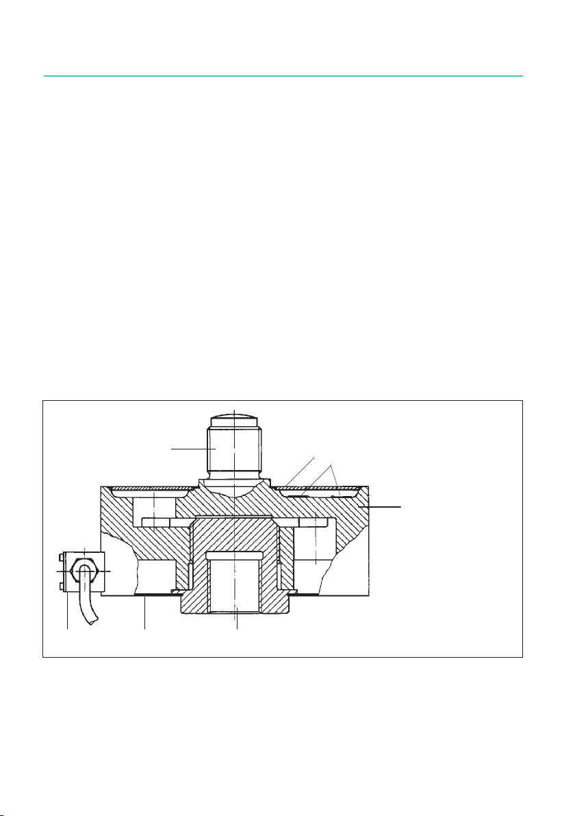
5.2 Strain gage covering agent
To protect the strain gage, the housing with the integrated range spring system is hermet
ically sealed on its top and bottom by metallic membranes so that no moisture can dam
age the sensitive application. This method provides the strain gages with a high degree
of protection against environmental influences. In order to retain their protective effect,
the metallic membranes must not be damaged in any way.
42
3
1
625
1 Measuring body
2 Closure membranes
3 Strain gage
4 Threaded pin
5 Cable box
6 Threaded hole
Fig. 5.1 Strain gage covering agent

11
Z4A
STRUCTURE AND MODE OF OPERATION
5.3 Disturbance variables
Torsion, bending and lateral loads are disturbance variables and therefore to be avoided.
HBM mounting aids can be used if necessary. The temperature effects on the zero signal
(strain gage bridge and housing) and on the sensitivity are compensated. Changes in
ambient pressure act as additive (subtractive) forces. Compared to high nominal loads,
these are hardly crucial.

Z4A
CONDITIONS ON SITE
12
6 CONDITIONS ON SITE
Protect the transducer from weather conditions such as rain, snow, ice, and salt water.
6.1 Ambient temperature
The effects of temperature on the zero signal and rated output are compensated. To
obtain optimum measurement results, comply with the nominal (rated) temperature
range. The strain gages are designed and arranged to ensure a high insensitivity to tem
perature gradients. Nevertheless, constant and at most slowly changing temperatures
have a favorable effect on accuracy.
Temperature-related measurement errors can be caused by heating on one side (e.g.
radiant heat) or by cooling. A radiation shield and thermal insulation on all sides provide
marked improvement, but must not be allowed to create a force shunt.
6.2 Moisture and corrosion protection
The force transducers are hermetically encapsulated and are therefore very insensitive to
moisture. Nevertheless, extreme humidity or tropical climate should be avoided if the
values are outside the classified limits (degree of protection IP67 as per DIN EN 60529).
With regard to steel force transducers, note that acids and all substances that release
ions also attack stainless steels and their weld seams. The potential resulting corrosion
can lead to failure of the force transducer. In this case, appropriate protective measures
must be provided.
6.3 Chemical influences
The steel transducer housings are protected by a powder coating. If they are used in
harsh environmental conditions (direct weathering, contact with corrosive media), users
should take additional protective measures. Apply a commercial protective coating finish
or a tar-based topcoat (underseal). The sheath of the connecting cable is made of sili
cone rubber. The uncoated force application areas are greased for corrosion protection.
Ensure that they are permanently greased.
6.4 Deposits
Dust, dirt and other foreign matter must not be allowed to accumulate to such an extent
that some of the measuring force is diverted, invalidating the measured value (force
shunt).

13
Z4A
MECHANICAL INSTALLATION
7 MECHANICAL INSTALLATION
7.1 Important precautions during installation
SHandle the transducer with care.
SBe sure to observe the requirements for the force application parts according to the
following sections of this manual.
SWelding currents must not be allowed to flow over the transducer. If there is a risk
that this might happen, you must use a suitable low-ohm connection to electrically
bypass the transducer. HBM provides the highly flexible EEK ground cable for this
purpose, for example, that is screwed on above and below the transducer.
SMake sure that the transducer cannot be overloaded.
SBe sure to observe the screw-in depths of the connected force application parts, such
as threaded rods or knuckle eyes (see below).
WARNING
There is a danger of the transducer breaking if it is overloaded. This could endanger the
operating personnel of the equipment in which the transducer is installed.
Implement appropriate safety measures to avoid a force overshoot or to protect against
resulting dangers. The maximum possible mechanical stresses, especially the breaking
force,are noted in the specifications.
During installation and operation of the transducer, observe the maximum parasitic forces
- lateral forces, bending moments and torques, see technical data - and the maximum per
missible load capacity of the force application parts being used.
7.2 General installation guidelines
The forces to be measured must act on the transducer as accurately as possible in the
direction of measurement. Torsional and bending moments, eccentric loading and lateral
forces can produce measurement errors and can destroy the transducer if limit values
are exceeded.
The customer's own structural elements must meet the following conditions:
SThe upper and lower force application parts must be aligned as accurately as possible
in one axis. Installation is made easier by centering aids on the underside. The center
ing diameter corresponds to dimension P, the effective centering depth is 3 mm.
SThe force application surfaces must be absolutely clean and fully load-bearing.
SWhen measuring compressive forces, make sure the support structure is rigid.
SThe external thread (provided by the customer) for connection to the lower internal
thread of the sensor must comply with a thread tolerance of 6g.
SThe threads must be cleaned of any deposits and soaked with graphite-free grease
before being screwed in.

Z4A
MECHANICAL INSTALLATION
14
Fnom: Force in direction of measurement
Fex: Force parallel to direction of measurement,
but outside center of force transducer
FQ: Force vertical to direction of measurement
Mb: Bending moment
Md: Torque
Fig. 7.1 Parasitic loads
The Z4A is a high-quality reference transducer. It is advisable to always have the sensor
calibrated with the loading fittings with which it is planned to use the sensor. Placing an
order for measurement chain calibration will ensure maximum certainty of measure
ments.

15
Z4A
MECHANICAL INSTALLATION
Notice
If you want to use the sensor to measure alternating dynamic loads, we advise you to pre-
stress the threads. (see section 7.3). Pre-stressing only serves to protect the thread, which
could be damaged by a long-term, alternating dynamic load in a mounting that has not
been pre-stressed. If only a few alternating loads are to be measured, you can use the sen
sor without pre-stressing without reducing accuracy. There is no need for pre-stressing if
measurements are only in the tensile range or in the compressive range.
7.3 Mounting with pre-stress
If the Z4A are being used to measure alternating dynamic loads (tensile and compressive
forces) over the long term, we recommend mounting the threaded connector with a pre-
stress that exceeds the greatest force to be measured by at least 10 %.
If the sensor is mounted in this way, it will be permanently vibration-proof in accordance
with the technical data, and alternating loads and static forces will be detected without
fail.
Pliable (cardanic) tension/compression bars are recommended as connecting compo
nents.
SPre-stressing by defined tightening torque for measuring alternating loads
This method can be applied to all sensors up to a nominal (rated) force of 50 kN.
Screw the force application part onto the upper threaded pin as far as the retainer and
screw it into the lower internal thread of the force transducer. The force application parts
are then pre-stressed to the specified tightening torque.
Nominal (rated) force in kN Tightening torque MAin N·m
20 70
5.0200
Tip
As the transducers can only be pre-stressed up to a nominal (rated) force of 50 kN, we rec
ommend that you use a U10M for alternating loads as an alternative for higher nominal
(rated) forces.
7.4 Mounting with knuckle eyes
Knuckle eyes are used in this mounting variant. These mounting aids prevent the applica
tion to the transducer of torsional moments and, where two knuckle eyes are used, bend
ing moments, as well as lateral and oblique loads.

Z4A
MECHANICAL INSTALLATION
16
Pre-stressing the knuckle eyes is not possible. Knuckle eyes do not have high endurance
when the full oscillation bandwidth is used. The design of the Z4A allows knuckle eyes to
be used without loss of accuracy.
We recommend mounting the knuckle eyes offset by 90 degrees, to keep bending
moments from any direction away from the sensor.
Mount the knuckle eyes as follows:
SScrew the knuckle eye in as far as the retainer
SScrew the knuckle eye back about two turns
The dimensions of the knuckle eyes, as well as those of the Z4A with knuckle eyes, can
be found in the technical data.
Notice
Knuckle eyes are only suitable for static and quasi-static measurements. For applications
measuring alternating loads, we recommend pliable (cardanic) tension/compression bars
mounted under pre-stress (see section 7.3.)
Notes on mounting with knuckle eyes
1. Shaft diameter
When using a sensor with knuckle eyes mounted on one or both sides, make sure that the
shaft is the right size.
You will find the diameters of the knuckle eyes, suitable shafts and their recommended
tolerances in the tables below
Knuckle eye with internal thread
Knuckle eyes Nominal
diameter
Hole fitting
size
Recommended shaft
fitting size
1-Z4/20kN/ZGOW 16
H7 g6
1-Z4/2T/ZGOW 20
1-Z4/100kN/ZGOW 30
1-Z4/10T/ZGOW 50 +0.002
-0.014 f7
1-Z4/500kN/ZGOW 60 +0.003
-0.018
Tab. 7.1 Recommended fitting sizes/tolerances for shaft and hole – knuckle eye with
internal thread
17
Z4A
MECHANICAL INSTALLATION
Knuckle eye with external thread
Knuckle eyes Nominal
diameter
Hole fitting
size
Recommended shaft
fitting size
1-Z4/20kN/ZGUW 16
H7 g6
1-U2A/2T/ZGUW 20
1-Z4/100kN/ZGUW 30
1-U24/10T/ZGUW 50 +0.002
-0.014 f7
1-Z4/500kN/ZGUW 60 +0.003
-0.018
Tab. 7.2 Recommended fitting sizes/tolerances for shaft and hole – knuckle eye with
external thread
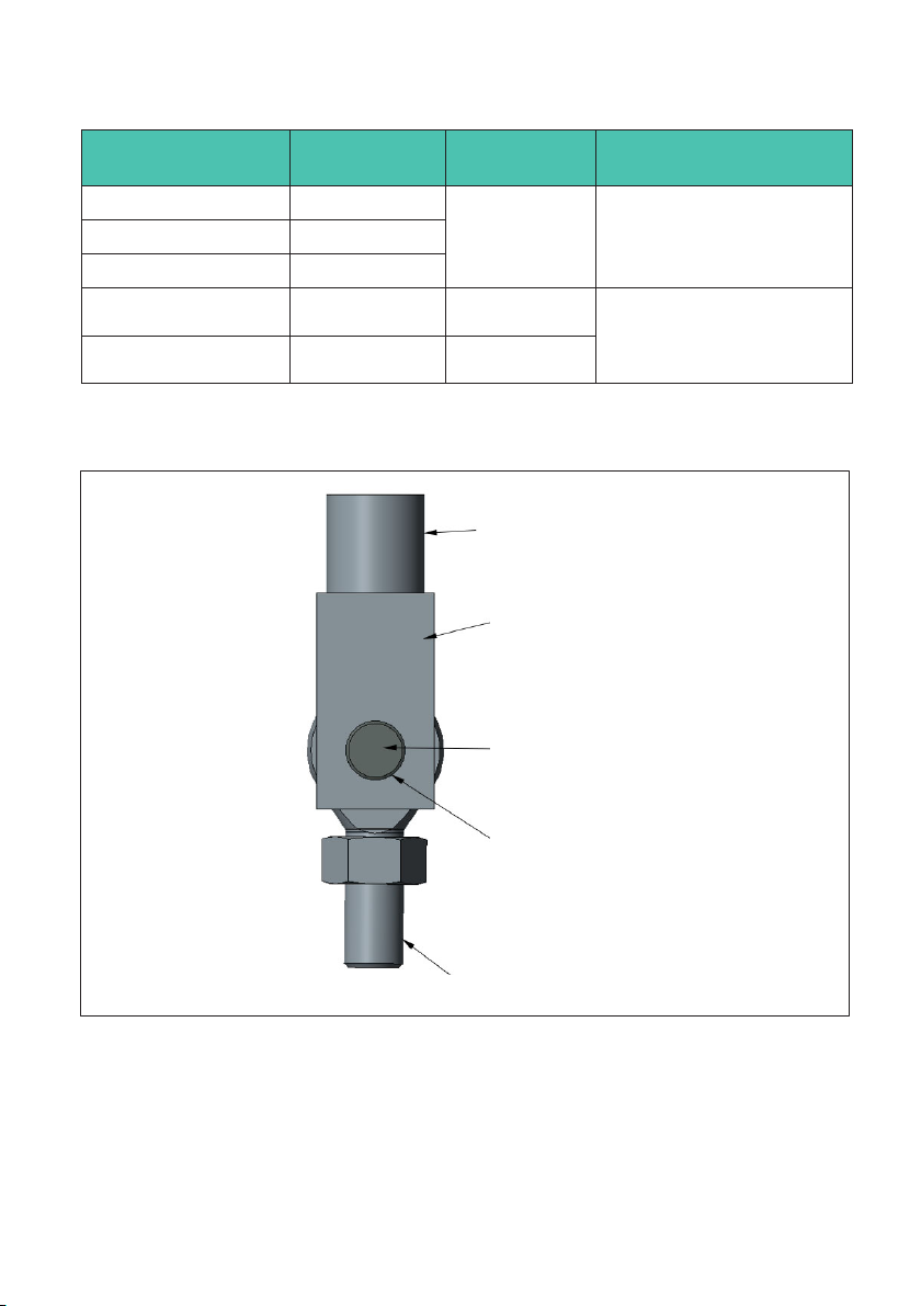
Customer's construction
Customer's shaft holder
Shaft
Play based on recommended fitting
size, see Tab. 7.1 or Tab. 7.2, page 16
Threaded connector for mounting
on force transducers
Fig. 7.2 Example diagram of installation with knuckle eye
Z4A
MECHANICAL INSTALLATION
18
CAUTION
If a shaft with an overly small diameter is used, the bearing of the knuckle eye will be
subjected to linear load. This subjects the inner bearing shell to excessive load, which can
lead to damage and, if forces are high, can cause the knuckle eye bearing to break.
Select the shaft as recommended in the mounting instructions.
2. Distance between knuckle eye and shaft bearing
The shaft support must allow for suitable play between the knuckle eye and the shaft
bearing.
CAUTION
If there is too much distance between the knuckle eye and the shaft bearing, this generates
bending moments in the shaft, causing it to deform.
This deformation puts strain on points of the edges of the inner bearing shell, which can
cause the knuckle eye or shaft to suffer damage or break.
Select the play as recommended in the mounting instructions.
To determine the play between the knuckle eye and the shaft bearing, you can apply the
following rule of thumb:
Shaft diameter Play between knuckle eye and bearing
≤30 mm 1/10 of the nominal diameter
>30 mm 1/20 of the nominal diameter
Tab. 7.3 Rule of thumb for determining play between knuckle eye and shaft bearing
Based on this, recommendations for the play between the knuckle eye and shaft bearing
are as follows:
Knuckle eye Play between knuckle eye and shaft bearing
1-Z4/20kN/ZGOW 1.6 mm
1-U24/20kN/ZGUW
1-U2A/2T/ZGOW 2 mm
1-U2A/2T/ZGUW
1-Z4/100kN/ZGOW 3 mm
1-Z4/100kN/ZGUW
1-U2A/10T/ZGOW 2.5 mm
1-U2A/10T/ZGUW
This manual suits for next models
5
Table of contents
Languages:
Other HBK Measuring Instrument manuals


