HBM SLB-700A User manual

A2112-1.0 de/en/fr
Dehnungsaufnehmer
Strain transducer
Extensomètre
SLB-700A
Montageanleitung
Mounting instructions
Notice de montage

Deutsch Seite 3 −11. . . . . . . . . . . . . . . . . . . . . . . . . . . . . . . . . . . . . . . . . . . . . . . .
English Page 12 −19. . . . . . . . . . . . . . . . . . . . . . . . . . . . . . . . . . . . . . . . . . . . . . . .
Français Page 20 −26. . . . . . . . . . . . . . . . . . . . . . . . . . . . . . . . . . . . . . . . . . . . . . .

3
SLB-700A
HBMA2112-1.0 de/en/fr
Inhalt Seite
Sicherheitshinweise 4. . . . . . . . . . . . . . . . . . . . . . . . . . . . . . . . . . . . . . . . . . . . .
1 Anwendungen 7. . . . . . . . . . . . . . . . . . . . . . . . . . . . . . . . . . . . . . . . . . . . .
2 Messprinzip 7. . . . . . . . . . . . . . . . . . . . . . . . . . . . . . . . . . . . . . . . . . . . . . . .
3 Montage 7. . . . . . . . . . . . . . . . . . . . . . . . . . . . . . . . . . . . . . . . . . . . . . . . . . .
4 Elektrischer Anschluss 8. . . . . . . . . . . . . . . . . . . . . . . . . . . . . . . . . . . . .
5 Mechanische Störeinflüsse 8. . . . . . . . . . . . . . . . . . . . . . . . . . . . . . . . . .
6 Technische Daten 9. . . . . . . . . . . . . . . . . . . . . . . . . . . . . . . . . . . . . . . . . .
7 Abmessungen (in mm) 10. . . . . . . . . . . . . . . . . . . . . . . . . . . . . . . . . . . . . .

4SLB-700A
HBM A2112-1.0 de/en/fr
Sicherheitshinweise
Bestimmungsgemäßer Gebrauch
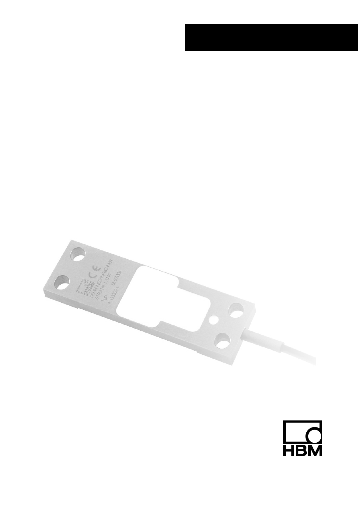
Der Dehnungsaufnehmer SLB700A ist für statische und dynamische Deh-
nungsmessungen zu verwenden. Jeder darüber hinausgehende Gebrauch gilt
als nicht bestimmungsgemäß.
Zur Gewährleistung eines sicheren Betriebes darf der Aufnehmer nur nach
den Angaben in der Montageanleitung verwendet werden. Bei der Verwen-
dung sind zusätzlich die für den jeweiligen Anwendungsfall erforderlichen
Rechts-und Sicherheitsvorschriften zu beachten. Sinngemäß gilt dies auch
bei Verwendung von Zubehör.
Der Aufnehmer ist kein Sicherheitselement im Sinne des bestimmungsgemä-
ßen Gebrauchs. Der einwandfreie und sichere Betrieb dieses Aufnehmers
setzt sachgemäßen Transport, fachgerechte Lagerung, Aufstellung und Mon-
tage sowie sorgfältige Bedienung und Instandhaltung voraus.
Allgemeine Gefahren bei Nichtbeachten der Sicherheitshinweise
Der Dehnungsaufnehmer SLB700A entspricht dem Stand der Technik und ist
betriebssicher. Von den Aufnehmern können Restgefahren ausgehen, wenn
sie von ungeschultem Personal unsachgemäß eingesetzt und bedient wer-
den.
Jede Person, die mit Aufstellung, Inbetriebnahme, Wartung oder Reparatur
eines Kraftaufnehmers beauftragt ist, muss die Montageanleitung und insbe-
sondere die sicherheitstechnischen Hinweise gelesen und verstanden haben.
Restgefahren
Der Leistungs- und Lieferumfang des Aufnehmers deckt nur einen Teilbereich
der Kraftmesstechnik ab. Sicherheitstechnische Belange der Kraftmesstech-
nik sind zusätzlich vom Anlagenplaner/Ausrüster/Betreiber so zu planen, zu
realisieren und zu verantworten, dass Restgefahren minimiert werden. Jeweils
existierende Vorschriften sind zu beachten. Auf Restgefahren im Zusammen-
hang mit der Kraftmesstechnik ist hinzuweisen.

5
SLB-700A
HBMA2112-1.0 de/en/fr
In dieser Montageanleitung wird auf Restgefahren mit folgenden Symbolen
hingewiesen:
Symbol: GEFAHR
Bedeutung: Höchste Gefahrenstufe
Weist auf eine unmittelbar gefährliche Situation hin, die −wenn die Sicher-
heitsbestimmungen nicht beachtet werden −Tod oder schwere Körperverlet-
zung zur Folge haben wird.
Symbol: WARNUNG
Bedeutung: Gefährliche Situation
Weist auf eine mögliche gefährliche Situation hin, die −wenn die Sicherheits-
bestimmungen nicht beachtet werden −Tod oder schwere Körperverletzung
zur Folge haben kann.
Symbol: ACHTUNG
Bedeutung: Möglicherweise gefährliche Situation
Weist auf eine mögliche gefährliche Situation hin, die −wenn die Sicherheits-
bestimmungen nicht beachtet werden −Sachschaden, leichte oder mittlere
Körperverletzung zur Folge haben könnte.
Symbol: HINWEIS
Weist darauf hin, dass wichtige Informationen über das Produkt oder über die
Handhabung des Produktes gegeben werden.
Symbol:
Bedeutung: CE-Kennzeichnung
Mit der CE-Kennzeichnung garantiert der Hersteller, dass sein Produkt den
Anforderungen der relevanten EG-Richtlinien entspricht (die Konformitätser-
klärung finden Sie unter http://www.hbm.com/HBMdoc).

6SLB-700A
HBM A2112-1.0 de/en/fr
Symbol:
Bedeutung: Gesetzlich vorgeschriebene Kennzeichnung zur Entsorgung
Nicht mehr gebrauchsfähige Altgeräte sind gemäß den nationalen und örtli-
chen Vorschriften für Umweltschutz und Rohstoffrückgewinnung getrennt von
regulärem Hausmüll zu entsorgen.
Falls Sie weitere Informationen zur Entsorgung benötigen, wenden Sie sich
bitte an die örtlichen Behörden oder an den Händler, bei dem Sie das Produkt
erworben haben.
Verbot von eigenmächtigen Umbauten und Veränderungen
Der Aufnehmer darf ohne unsere ausdrückliche Zustimmung weder konstruk-
tiv noch sicherheitstechnisch verändert werden. Jede Veränderung schließt
eine Haftung unsererseits für daraus resultierende Schäden aus.
Qualifiziertes Personal
Diese Aufnehmer sind nur von qualifiziertem Personal ausschließlich entspre-
chend der technischen Daten in Zusammenhang mit den nachstehend ausge-
führten Sicherheitsbestimmungen und Vorschriften einzusetzen. Hierbei sind
zusätzlich die für den jeweiligen Anwendungsfall erforderlichen Rechts- und
Sicherheitsvorschriften zu beachten. Sinngemäß gilt dies auch bei Verwen-
dung von Zubehör.
Qualifiziertes Personal sind Personen, die mit Aufstellung, Montage, Inbe-
triebsetzung und Betrieb des Produktes vertraut sind und die über die ihrer
Tätigkeit entsprechende Qualifikationen verfügen.
Bedingungen am Aufstellungsort
Schützen Sie den Aufnehmer vor Feuchtigkeit oder Witterungseinflüssen wie
beispielsweise Regen, Schnee usw.
Wartung
Der Dehnungsaufnehmer SLB700A ist wartungsfrei.
Unfallverhütung
Obwohl die angegebene Nenndehnung im Zerstörungsbereich ein Mehrfa-
ches vom Messbereichsendwert beträgt, müssen die einschlägigen Unfallver-
hütungsvorschriften der Berufsgenossenschaften berücksichtigt werden.

7
SLB-700A
HBMA2112-1.0 de/en/fr
1 Anwendungen
Der Dehnungsaufnehmer SLB700A misst statische und dynamische Dehnun-
gen bzw. Stauchungen an Stahlkonstruktionen.
Anwendungsschwerpunkte sind Überwachungsfunktionen an Kränen, Behäl-
tern, Brücken, Pressen, Walzgerüsten und ähnlichen Konstruktionen. Durch
die einfache Befestigung über vier Schrauben läßt sich der SLB700A auch
nachträglich in schon bestehende Konstruktionen einbauen.
2 Messprinzip
Über die vier Schrauben wird eine kraftschlüssige Verbindung zwischen dem
Dehnungsaufnehmer SLB700A und dem Messobjekt sichergestellt. Durch
mechanische Belastung ergibt sich eine Längenänderung am Messobjekt, die
auf den SLB700A übertragen wird. Aufgrund der Längenänderung ändert sich
der elektrische Widerstand der applizierten Dehnungsmessstreifen proportio-
nal zur Dehnung. Liegt eine Brückenspeisespannung an, so liefert die Schal-
tung ein Ausgangssignal, das proportional der Widerstandsänderung ist und
damit auch proportional der Längenänderung. Durch einen für Dehnungs-
messstreifen geeigneten Trägerfrequenz- oder Gleichspannungsverstärker er-
folgt die weitere Auswertung des Messsignals.
3 Montage
Der Dehnungsaufnehmer SLB700A wird mittels vier handelsüblicher Innen-
sechskantschrauben M6 (z.B. DIN 912) auf das Messobjekt angeschraubt.
Wir empfehlen Schrauben der Festigkeitsklasse 12.9, die mit einem Anzugs-
drehmoment von 16 N⋅m in diagonal versetzter Reihenfolge angezogen wer-
den sollten. Alternativ können Schrauben der Festigkeitsklasse 8.8 mit einem
Anzugsdrehmoment von 8 N⋅m eingesetzt werden. Der Dehnungsaufnehmer
darf nicht in dem mittleren, abgesetzten Bereich aufliegen und muss verspan-
nungsfrei montiert werden.
hier nicht belasten

8SLB-700A
HBM A2112-1.0 de/en/fr
Die Oberflächenbeschaffenheit (Rav3.2) des Messobjektes muss ausrei-
chend eben sein.
Lack- und Farbreste müssen im Montagebereich des Aufnehmers unbedingt
vermieden werden.
Bei guter Oberflächenbeschaffenheit wird das Nullsignal des aufgeschraubten
Dehnungsaufnehmers bei ca. 10 % des Nutzsignals liegen. Bei freier Bewitte-
rung und Gefahr mechanischer Beschädigung sollte der Aufnehmer mit einem
Gehäuse abgedeckt werden (auf Schwitzwasser achten! ).
4 Elektrischer Anschluss
Der Dehnungsaufnehmer ist mit einem 6 m langen, vieradrigen Anschlusska-
bel ausgerüstet und in Vierleiter-Technik kalibriert.
Kabelbelegung SLB700A/06
Anschluss Aderfarbe
Brückenspeisespannung (+) blau
Brückenspeisespannung (−) schwarz
Messsignal (+) weiß
Messsignal (−) rot
Kabelschirm mit Gehäuse verbunden
Zur Parallelschaltung mehrerer SLB700A werden Kabeladern gleicher Farbe
zusammengeschaltet. Die Parallelschaltung empfiehlt sich besonders bei
Überlagerung des Nutzsignals durch Biegung, wie sie zum Beispiel durch
Windlasten oder durch nicht zentrische Krafteinleitungen entstehen kann. Die
Dehnungsaufnehmer müssen so angebracht werden, dass jeweils ein Aufneh-
mer den Biegestauchungen, der andere den Biegedehnungen ausgesetzt ist.
Durch die Parallelschaltung werden die entgegengerichteten Ausgangssignale
arithmetisch gemittelt und somit das Störsignal durch Biegung kompensiert.
5 Mechanische Störeinflüsse
Der Messkörper des SLB700A ist so ausgelegt, dass er weitestgehend Stö-
reinflüsse aufgrund von Torsion oder Biegung kompensiert.
Darüber hinaus kann ein zweiter, gegenüberliegend angeschraubter und par-
allelgeschalteter SLB700A diese überlagerten Störgrößen minimieren.

9
SLB-700A
HBMA2112-1.0 de/en/fr
6 Technische Daten
Typ SLB700A/06
Nenndehnung µm/m 500
Nennkennwert mV/V 1,5"0,15
Rückstellkraft N 3110
Nullpunktabweichung % 5
Temperaturkoeffizient des Kennwertes pro 10 K % 0,2
Temperaturkoeffizient des Nullpunktes pro 10 K % 0,5
Kompensierter Temperaturbereich °C−10...+40
Eingangswiderstand Ω>1000
Ausgangswiderstand Ω1000 +10
Isolationswiderstand GΩ5
Nennbereich der Speisespannung V 2...15
Max. Gebrauchsdehnung % 150
Bruchdehnung % 300
Nennmessweg mm ca. 0,038
Kabellänge m 6
Kabeldurchmesser mm ca. 3
Gewicht (inkl. 6 m Kabel) kg 0,16
Schutzart nach EN 60 529 IP65

10 SLB-700A
HBM A2112-1.0 de/en/fr
7 Abmessungen (in mm)
∅6,6 (entgratet <0,3 mm)
76,2
6,4
89
vieradriges Kabel
∅ca. 3
16
6,4
16
25,4
14,3 5,55

11
SLB-700A
HBMA2112-1.0 de/en/fr
Contents Page
Safety instructions 12. . . . . . . . . . . . . . . . . . . . . . . . . . . . . . . . . . . . . . . . . . . . . .
8 Applications 15. . . . . . . . . . . . . . . . . . . . . . . . . . . . . . . . . . . . . . . . . . . . . . .
9 Principle of measurement 15. . . . . . . . . . . . . . . . . . . . . . . . . . . . . . . . . . .
10 Mounting 15. . . . . . . . . . . . . . . . . . . . . . . . . . . . . . . . . . . . . . . . . . . . . . . . . .
11 Electrical connection 16. . . . . . . . . . . . . . . . . . . . . . . . . . . . . . . . . . . . . . .
12 Mechanical interference effects 16. . . . . . . . . . . . . . . . . . . . . . . . . . . . . .
13 Specifications 17. . . . . . . . . . . . . . . . . . . . . . . . . . . . . . . . . . . . . . . . . . . . . .
14 Dimensions (in mm) 18. . . . . . . . . . . . . . . . . . . . . . . . . . . . . . . . . . . . . . . .

12 SLB-700A
HBM A2112-1.0 de/en/fr
Safety instructions
Use in accordance with the regulations
The SLB700A strain transducer should be used for static and dynamic strain
measurements. Use for any additional purpose shall be deemed to be not in
accordance with the regulations.
In the interests of safety, the transducer should only be operated as described
in the Mounting Instructions. It is also essential to observe the appropriate
legal and safety regulations for the application concerned during use. The
same applies to the use of accessories.
The transducer is not a safety element within the meaning of its use as
intended. Proper and safe operation of this transducer requires proper
transportation, correct storage, assembly and mounting and careful operation
and maintenance.
General dangers due to non-observance of the safety instructions
The SLB700A strain transducer corresponds to the state of the art and is
fail-safe. The transducers can give rise to residual dangers if they are
inappropriately installed and operated by untrained personnel.
Everyone involved with the installation, commissioning, maintenance or repair
of a force transducer must have read and understood the Mounting
Instructions and in particular the technical safety instructions.
Residual dangers
The scope of supply and performance of the transducer covers only a small
area of force measurement technique. In addition, equipment planners,
installers and operators should plan, implement and respond to the safety
engineering considerations of force measurement technique in such a way as
to minimise residual dangers. Prevailing regulations must be complied with at
all times. There must be reference to the residual dangers connected with
force measurement technique.

13
SLB-700A
HBMA2112-1.0 de/en/fr
In these mounting instructions residual dangers are pointed out using the
following symbols:
Symbol: DANGER
Meaning: Highest level of danger
Warns of a directly dangerous situation in which failure to comply with safety
requirements will lead to death or serious physical injury.
Symbol: WARNING
Meaning: Dangerous situation
Warns of a potentially dangerous situation in which failure to comply with
safety requirements can lead to death or serious physical injury.
Symbol: ATTENTION
Meaning: Possibly dangerous situation
Warns of a potentially dangerous situation in which failure to comply with
safety requirements could lead to damage to property, slight or moderate
physical injury.
Symbol: NOTE
Refers to the fact that important information is being given about the product
or its use.
Symbol:
Meaning: CE mark
The CE mark signals a guarantee by the manufacturer that his product meets
the requirements of the relevant EC directives (the declaration of conformity is
available at http://www.hbm.com/HBMdoc).

14 SLB-700A
HBM A2112-1.0 de/en/fr
Symbol:
Meaning: Statutory marking requirements for waste disposal
National and local regulations regarding the protection of the environment and
recycling of raw materials require old equipment to be separated from regular
domestic waste for disposal.
For more detailed information on disposal, please contact the local authorities
or the dealer from whom you purchased the product.
Prohibition of own conversions and modifications
The transducer must not be modified from the design or safety engineering
point of view except with our express agreement. Any modification shall
exclude all liability on our part for any damage resulting therefrom.
Qualified personnel
These transducers are only to be installed by qualified personnel strictly in
accordance with the specifications and with the safety rules and regulations
which follow. It is also essential to observe the appropriate legal and safety
regulations for the application concerned. The same applies to the use of
accessories.
Qualified personnel means persons entrusted with the installation, fitting,
commissioning and operation of the product who possess the appropriate
qualifications for their function.
Conditions on site
Protect the transducer from damp and weather influences such as rain, snow,
etc.
Maintenance
The SLB700A strain transducer is maintenance free.
Accident prevention
Although the specified nominal strain in the destructive range is several times
the full scale value, the relevant accident prevention regulations from the
trade associations must be taken into consideration.

15
SLB-700A
HBMA2112-1.0 de/en/fr
1 Applications
The SLB700A strain transducer measures static and dynamic strains or
upsets to steel structures.
The application concentrates on monitoring functions on cranes, containers,
bridges, presses, roll stands and similar structures. Simply attached by four
screws, the SLB700A can also be subsequently fitted to existing structures.
2 Principle of measurement
The four screws maintain a solid connection between the SLB700A strain
transducer and the measurement object. Mechanical loading produces a
change of length in the measurement object, which is conveyed to the
SLB700A. Because there is a change in length, the electrical resistance of the
applied strain gauge also changes in proportion to the strain. If there is
excitation voltage, the circuit supplies an output signal proportional to the
change in resistance and therefore also proportional to the change in length.
A carrier frequency or DC amplifier suitable for strain gauges enables
measurement signal evaluation to continue.
3 Mounting
The SLB700A strain transducer is attached to the measurement object by
means of four normal M6 hexagon socket screws (e.g. DIN 912). We
recommend screws of resistance class 12.9, which should be tightened in a
sequence of diagonal opposites, using a tightening torque of 16 N⋅m.
Alternatively, use screws of resistance class 8.8 and a tightening torque of
8 N⋅m. The strain transducer must not be mounted in the central, offset area
and it must be installed free from distortion.
do not put weight here

16 SLB-700A
HBM A2112-1.0 de/en/fr
The surface condition (Rav3.2) of the measurement object must be
sufficiently flat.
It is absolutely essential that there is no residual paint or varnish in the
transducer installation area.
Where the surface condition is good, the zero signal of the attached strain
transducer will be approx. 10 % of the useful signal. If open to the elements
and if there is a risk of mechanical damage, the transducer should be covered
by an enclosure (watch out for condensation water! ).
4 Electrical connection
The strain transducer comes with a 6 m long, four-wire connection cable and
is calibrated using four-wire technology.
SLB700A/06 cable assignment
Connection Wire colour
Excitation voltage (+) blue
Excitation voltage (−) black
Measurement signal (+) white
Measurement signal (−) red
Cable shield connected to enclosure
When connecting several SLB700As in parallel, wires of the same colour are
interconnected. Parallel connection is particularly recommended for beating
the useful signal by bending, such as can occur through wind loads or through
force introductions which are not centered. The strain transducers have to be
attached so that one transducer is always exposed to bending upsets, the
other to bending strains. The parallel connection enables the opposing output
signals to be determined arithmetically, thus compensating the interference
signal by bending.
5 Mechanical interference effects
The measuring body of the SLB700A is designed to compensate as much as
possible interference effects caused by torsion or bending.
In addition to this, a second SLB700A attached opposite and connected in
parallel, can minimise these superimposed disturbance variables.

17
SLB-700A
HBMA2112-1.0 de/en/fr
6 Specifications
Type SLB700A/06
Nominal strain µm/m 500
Nominal sensitivity mV/V 1.5"0.15
Restoring force N 3110
Zero deviation % 5
Temperature coefficient of characteristic value
per 10 K
% 0.2
Temperature coefficient of zero point per 10 K % 0.5
Compensated temperature range °C−10...+40
Input resistance Ω>1000
Output resistance Ω1000 +10
Isolation resistance GΩ5
Nominal range of the excitation voltage V 2...15
Max. operational strain % 150
Breaking strain % 300
Nominal displacement mm approx. 0.038
Cable length m 6
Cable diameter mm approx. 3
Weight (incl. 6 m cable) kg 0.16
Degree of protection acc. to EN 60 529 IP65

18 SLB-700A
HBM A2112-1.0 de/en/fr
7 Dimensions (in mm)
∅6.6 (deburred <0.3 mm)
76,2
6,4
89
four-wire cable
∅approx. 3
16
6,4
16
25,4
14,3 5,55

19
SLB-700A
HBMA2112-1.0 de/en/fr
Sommaire Page
Consignes de sécurité 20. . . . . . . . . . . . . . . . . . . . . . . . . . . . . . . . . . . . . . . . . . .
15 Applications 23. . . . . . . . . . . . . . . . . . . . . . . . . . . . . . . . . . . . . . . . . . . . . . .
16 Principe de mesure 23. . . . . . . . . . . . . . . . . . . . . . . . . . . . . . . . . . . . . . . . .
17 Montage 23. . . . . . . . . . . . . . . . . . . . . . . . . . . . . . . . . . . . . . . . . . . . . . . . . . .
18 Raccordement électrique 24. . . . . . . . . . . . . . . . . . . . . . . . . . . . . . . . . . .
19 Influences perturbatrices mécaniques 24. . . . . . . . . . . . . . . . . . . . . . .
20 Caractéristiques techniques 25. . . . . . . . . . . . . . . . . . . . . . . . . . . . . . . . .
21 Dimensions (en mm) 26. . . . . . . . . . . . . . . . . . . . . . . . . . . . . . . . . . . . . . . .

20 SLB-700A
HBM A2112-1.0 de/en/fr
Consignes de sécurité
Utilisation conforme
L’extensomètre SLB700A s’applique aux mesures d’extension statiques et
dynamiques. Toute autre utilisation est considérée comme non conforme.
Pour un fonctionnement en toute sécurité, le capteur doit être utilisé
conformément aux instructions de la notice de montage. De plus, il convient
de respecter les règlements et consignes de sécurité applicables à chaque
cas particulier. Ceci vaut également pour l’utilisation des accessoires.
Le capteur ne constitue pas un élément de sécurité au sens de l’utilisation
conforme. Afin de garantir un fonctionnement parfait et en sécurité du présent
capteur, il convient de respecter les conditions suivantes : transport, stockage,
installation et montage appropriés, maniement et entretien soigneux.
Risques généraux en cas de non-respect des consignes de sécurité
L’extensomètre SLB700A est conforme au niveau de développement
technologique actuel ; il est fiable. Néanmoins, le capteur peut présenter des
dangers résiduels en cas d’utilisation non conforme par du personnel non
qualifié.
Toute personne chargée de l’installation, de la mise en service, de la
maintenance ou de la réparation du capteur de force doit impérativement
avoir lu et compris la notice de montage et notamment les consignes de
sécurité.
Dangers résiduels
Les performances et l’étendue de la livraison de ce capteur ne couvrent
qu’une partie des techniques de mesure de force. La sécurité dans ce
domaine doit être conçue, mise en œuvre et prise en charge par l’ingénieur, le
constructeur et l’opérateur de manière à minimiser les dangers résiduels. Les
dispositions en vigueur doivent être respectées. Il convient de souligner les
dangers résiduels liés aux techniques de mesure de force.
Other manuals for SLB-700A
1
Table of contents
Languages:
Other HBM Transducer manuals
Popular Transducer manuals by other brands

Balluff
Balluff BTL7-V50E-M P-C003 Series user guide

Siemens
Siemens XRS-5 Quick start manual

Veris
Veris PX3 Series installation guide

Milltronics
Milltronics XLS Series instruction manual

Veris Industries
Veris Industries PW2 Series installation guide

LEI accessories
LEI accessories HS-NS Installation and operation instructions