Installation instructions and Instructions for use
Subject to technical modifications – Date of Issue
February/2023
5
CE marking
The HELLA concealed awning PM07 protect (side seam guided) is in compliance with the
declaration of performance according to the Construction Products Regulation; if the unit is
operated with a motor drive it is additionally in compliance with the Machinery Directive and
the Guideline for Electromagnetic Compatibility; in case of proper use, the awning
corresponds to the basic requirements of the harmonised standard EN 13561. The
respective declarations are deposited with the manufacturers.
*) Wind resistance classes according to product size [m²] - see chapter “Intended use”.
The CE identification applies for the delivery status of the product. The product mounted
meets the requirements of the specified standard only, if
during installation the information and instructions given in these instructions as well
as the information and instructions of the manufacturers of the screws have been
observed,
the product is installed with the recommended type and number of fasteners/screws.
No changes, rebuildings or extensions, with the exception of those described in these
instructions, are allowed with this product. The fixed CE-label expires with any change,
rebuilding or extension.
HELLA Sonnen- und Wetterschutztechnik GmbH
A-9913 Abfaltersbach 125
23
LE-PUMP-01-003
EN 13561:2004+A1:2008
Concealed awning side seam guided
PM07 protect
Exterior textile sun protection
Wind resistance class 3-6* - in connection
with the regulation (EU) 2019/1188
Installation instructions and Instructions for use
6
Subject to technical modifications – Date of Issue
February/2023
Safety instructions
These installation instructions refer to prefabricated elements, that (1) for
100% are made from parts, which are defined by us, and (2) which are
made in manufacturing processes, which are defined by us too; in all other
cases we do not provide any guarantee!
The safety instructions as well as the appropriate instructions must be read
carefully before installation and use. In case of non-observance of the
directions and information given in these instructions and in case of
improper installation and operation or unintended use, the manufacturer
shall not accept any warranty claims concerning any damage to the
product. In these cases, the liability for consequential damage to any parts
or persons is ruled out as well.
- Follow the described installation steps and pay attention to
recommendations and notes.
- Keep these instructions in a safe place.
- All installation and removal works, as well as maintenance and repair
works are only allowed to be carried out by authorised and qualified
specialist staff.
- If switching, automatic or radio control devices are used to operate the
units, the information given in the enclosed instructions of the
manufacturer must be observed.
- During operation do not put your hand into or touch movable parts.
- Ensure that clothing or body parts cannot get caught on the unit.
- Observe the regulations for prevention of accidents of the employer's
liability insurance association!
- Before operation check the unit for visible damage. If the unit is
damaged, it should not be used; please consult authorized specialist
staff immediately.
- Risk of injury and accident due to the weight of the product!
- Take safety measures against the danger of squashing, especially when
operating the unit with automatic devices.
- Place the operating switch within sight of the unit, but not near any of the
moving parts.
- Never let children play with the unit.
A sun protection device with electric drive cannot be retracted without
current. We therefore recommend the use of an emergency power
generating unit or a motor with an emergency crank handle, especially in
regions with frequent power failures.
Danger of suffocation!
Ensure that the foil cannot get into the hands of children. Keep the foil in a
safe place.
Installation instructions and Instructions for use
Subject to technical modifications – Date of Issue
February/2023
7
Safety instructions
ATTENTION!
For children/adults a lowered blind is
no protection against a fall out of the window!
Attention! Risk of injury or danger to life due to an electric shock!
- Set-up, examination, commissioning and error correction of the unit must
only be performed by authorised or trained expert staff (as per VDE
0100).
- Switch off the current to the connecting lines when working at the unit.
There is danger to life! Take safety precautions against unintentional
switching on!
- Check the electrical wires regularly for damage. Do not use the unit if
any damage is found.
- Our electrically driven units are in accordance with the regulations for
power plants acc. to VDE 0100. We cannot guarantee for the operational
reliability of the unit with non-approved modifications.
- White motor cables are not UV-resistant and must therefore be routed in
empty conduits, cable ducts, or similar.
- The enclosed installation instructions of the electrical devices supplied
must be observed.
Units with motor drive:
The drives used are operated with a voltage of AC 230V/50Hz. Please
check the power supply provided by your utility company before connecting.
Any other voltage can destroy the drives.
Installation instructions and Instructions for use
8
Subject to technical modifications – Date of Issue
February/2023
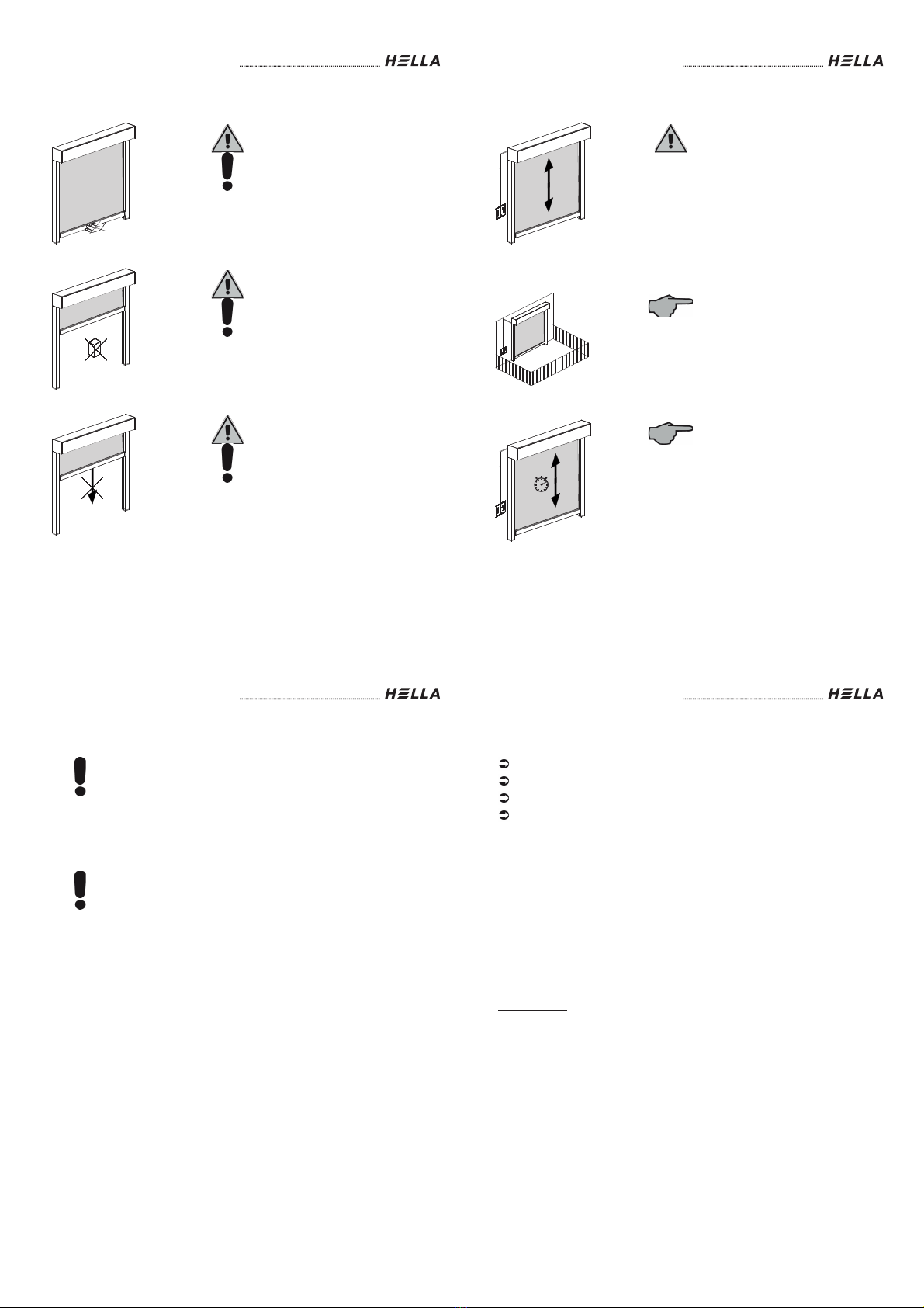
Operation of the sunblind in case of
storm:
If the wind speed exceeds the
tolerable limiting value, close the
windows or raise the sunblind to the
upper end position. Take care, that no
draught can arise, even during your
absence. If the window is open, the
closed sunblinds cannot withstand all
wind loads. The recommended wind
limit values can be ensured only with
a closed window.
Operation of the sunblind in case of
frost or rain:
In case of frost the sunblind can
freeze shut. Avoid using force to
operate the sunblind and do not use it,
if there is snow or ice in the guide
rails. Do not operate the unit if it is
frozen solid. With automatic control
devices it is necessary to switch the
automatic control device off, if there is
danger of freezing.
If the front-mounted blind is raised
whilst wet (e.g. after rain), it must be
lowered again later to dry the cover.
Range of movement of the
sunblind:
Please make sure that no obstacles
block the guide rails of the sunblind.