Hella APS-R Manual

Advanced People Sensor
APS-R and APS-R-PoE, SW 1.2
Installation and configuration manual
HAGL-120-00079, 2017-06, APS-R, APS-R-PoE, SW 1.2
HAGL-120-00079, 2017-06, APS-R, APS-R-PoE, SW 1.2

© 2017 HELLA AGLAIA Mobile Vision GmbH, Berlin (hereinafter 'Hella Aglaia')
HELLA AGLAIA Mobile Vision GmbH
Ein Unternehmen der HELLA Gruppe
Ullsteinstrasse 140
12109 Berlin
Telephone: +49 30 200 04 29 632
Fax: +49 30 200 04 29 109
Email: [email protected]
Germany
Internet: www.people-sensing.com
Till 07.07.2017 the company headquarters will be located at
Treskowstrasse 14, 13089 Berlin
2
09.06.2017 The reproduction, distribution and utilization of this document as well as the communication of its contents to others
without express authorization is prohibited. Offenders will be held liable for the payment of damages.
All rights reserved in the event of the grant of patent, utility model or design.

© 2017 HELLA AGLAIA Mobile Vision GmbH. All rights reserved. This manual is protected by copyright. It
may not be reproduced, either in whole or in part, or stored in a database or a data backup system without
the prior written consent of HELLA AGLAIA Mobile Vision GmbH, nor transmitted in any form, either elec-
tronically or mechanically, including photocopying and recording. Violations are subject to the criminal pro-
visions of the Copyright Act.
HELLA AGLAIA Mobile Vision GmbH reserves the right to revise or replace this manual at any time and
without prior notice. Make sure that you have the most current version of this manual. Please don’t hesitate
to contact HELLA AGLAIA Mobile Vision GmbH with any questions.
HELLA AGLAIA Mobile Vision GmbH does not guarantee the completeness, accuracy, or timeliness of the
laws, guidelines, or regulations referred to or quoted, whether directly or indirectly, in this manual. It is the
responsibility of the user to become familiar with the current laws, guidelines, and regulations that apply to
their work.
HELLA AGLAIA Mobile Vision GmbH reserves the right to modify the described devices (including the
respective software) without prior notice, irrespective of the content of this manual. Unless expressly
agreed upon in writing, HELLA AGLAIA Mobile Vision GmbH is not obligated to notify the owner or user of
the devices described in this manual (including the respective software) of any revisions, updates, or modi-
fications without further request.
With regard to the people counter, HELLA AGLAIA Mobile Vision GmbH‘s liability is limited to the terms of
the warranty described in this manual. The information provided in this manual is not a warranty or guar-
antee of any kind. Stipulations concerning the devices described in this manual are only deemed warran-
ties if they are expressly referred to as such in writing and contain a description of the warranty’s scope
and the product covered by the warranty.
The product and company names mentioned in this manual may be protected trademarks of other manu-
facturers. HELLA AGLAIA Mobile Vision GmbH will be happy to provide you with circuit diagrams, parts
lists of the components used in the respective devices, descriptions, or other information to enable author-
ized personnel of the user to repair those device components that are deemed repairable by HELLA
AGLAIA Mobile Vision GmbH.
The information contained in this manual has been prepared by HELLA AGLAIA Mobile Vision GmbH with
great care using sources available to HELLA AGLAIA Mobile Vision GmbH. However, HELLA AGLAIA
Mobile Vision GmbH shall not be responsible for any errors, incorrect or incorrectly compiled data, and any
consequences resulting therefrom, irrespective of the legal basis, provided that HELLA AGLAIA Mobile
Vision GmbH‘s conduct amounts to no more than ordinary negligence.
The aforementioned exclusion of liability does not apply to damages resulting from injury to life, body, or
health or to damages that are caused intentionally, by gross negligence on the part of HELLA AGLAIA
Mobile Vision GmbH, or by the violation of due diligence requirements in connection with the development,
manufacture, and distribution of the products described in this manual.
This does not affect the liability regardless of negligence or fault pursuant to legal regulations such as the
Product Liability Act.
Copyright information
Supplemental instructions
09.06.2017 3
The reproduction, distribution and utilization of this document as well as the communication of its contents to others
without express authorization is prohibited. Offenders will be held liable for the payment of damages.
All rights reserved in the event of the grant of patent, utility model or design.

Table of contents
1 Overview............................................................................................................................................... 6
2 General information............................................................................................................................. 7
2.1 About this document.................................................................................................................... 7
2.2 About the manufacturer............................................................................................................... 7
2.3 Limitation of liability..................................................................................................................... 8
2.4 Scope of delivery......................................................................................................................... 8
2.5 Use of the Advanced People Sensor.......................................................................................... 8
2.6 Data protection............................................................................................................................ 9
3 Structure and function...................................................................................................................... 10
3.1 Hardware................................................................................................................................... 10
3.2 Functionality.............................................................................................................................. 14
3.3 Re-entry and re-exit detection ('Repassing' / 'U-turns')............................................................. 16
4 Technical data.................................................................................................................................... 17
4.1 Mechanical data........................................................................................................................ 17
4.2 Hardware interface specifications............................................................................................. 18
4.2.1 Ethernet...................................................................................................................... 18
4.2.2 I/O-Port....................................................................................................................... 19
4.3 Electrical data............................................................................................................................ 21
4.4 Optical data............................................................................................................................... 22
4.5 Environmental conditions.......................................................................................................... 23
4.6 Product labels............................................................................................................................ 24
5 Installation.......................................................................................................................................... 25
5.1 Requirements............................................................................................................................ 25
5.2 Recessed mounting................................................................................................................... 26
6 Configuration..................................................................................................................................... 27
6.1 Preparation................................................................................................................................ 27
6.2 Basic operations........................................................................................................................ 29
6.3 Start Page - live view................................................................................................................. 32
6.4 Camera Position........................................................................................................................ 33
6.5 Counting.................................................................................................................................... 37
6.6 Data Recording......................................................................................................................... 38
6.7 Network..................................................................................................................................... 41
6.8 Other Settings........................................................................................................................... 43
6.9 Service Tools............................................................................................................................. 44
6.10 About......................................................................................................................................... 46
6.11 Diagnostics................................................................................................................................ 47
7 Cleaning, maintenance and troubleshooting.................................................................................. 49
7.1 Cleaning.................................................................................................................................... 49
7.2 Maintenance.............................................................................................................................. 49
Table of contents
4 09.06.2017 The reproduction, distribution and utilization of this document as well as the communication of its contents to others
without express authorization is prohibited. Offenders will be held liable for the payment of damages.
All rights reserved in the event of the grant of patent, utility model or design.

7.3 Troubleshooting......................................................................................................................... 49
8Disposal.............................................................................................................................................. 51
9 Appendix............................................................................................................................................ 52
9.1 Detection area........................................................................................................................... 52
9.2 Ordering Information................................................................................................................. 52
9.3 Menu Structure.......................................................................................................................... 53
9.4 List of used IP ports................................................................................................................... 56
9.5 Software licenses...................................................................................................................... 57
9.6 CE Declaration of Conformity.................................................................................................... 58
10 Glossary and abbreviations............................................................................................................. 60
11 Index................................................................................................................................................... 62
Table of contents
09.06.2017 5
The reproduction, distribution and utilization of this document as well as the communication of its contents to others
without express authorization is prohibited. Offenders will be held liable for the payment of damages.
All rights reserved in the event of the grant of patent, utility model or design.
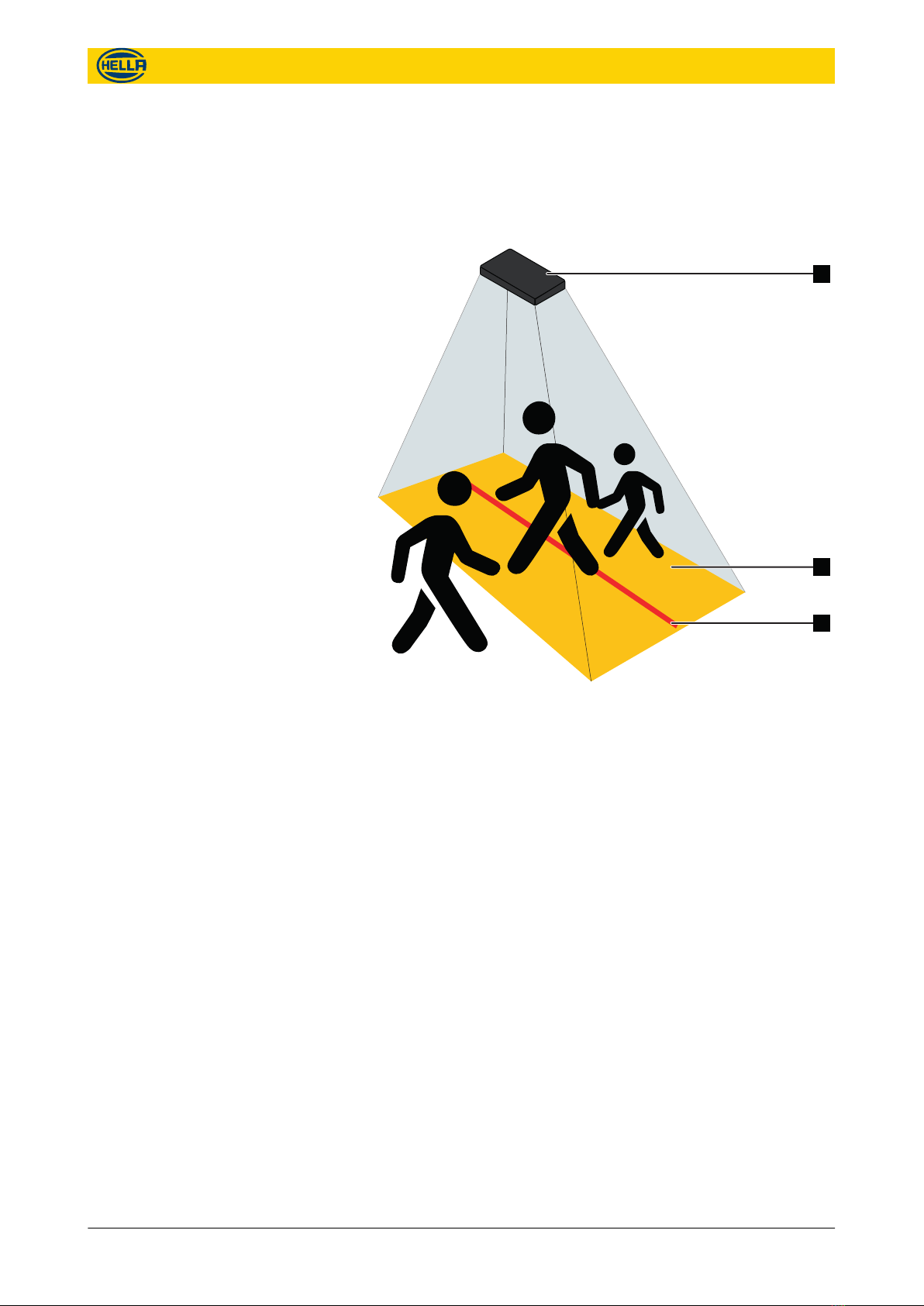
1 Overview
The Advanced People Sensor (APS) counts persons within the
configured area/monitored area based on stereoscopic imaging
and image processing. The counting data is stored internally and
can be transferred via different interfaces for external processing.
3
2
1
Fig. 1: People sensing
1 Advanced People Sensor (APS)
2 Configured area/monitored area
3 Counting line
The results can be verified using video recording (optional). This
enables a precise proof of the counting accuracy.
Overview
6 09.06.2017 The reproduction, distribution and utilization of this document as well as the communication of its contents to others
without express authorization is prohibited. Offenders will be held liable for the payment of damages.
All rights reserved in the event of the grant of patent, utility model or design.

2 General information
2.1 About this document
This manual provides information for optimal configuration and
efficient operation of the device.
Personnel must carefully read and fully understand this manual
before performing any installation or configuration tasks.
The figures in this manual are for information only. Actual design
may differ from illustrations.
This document is addressed to system integrators.
All information in this manual refers to software version 1.2 and
hardware APS-R, APS-R-PoE.
Modifications to the functionality which will be implemented through
future software updates will be described in separate release notes
or in an updated version of the manual.
Notes and safety instructions are marked by symbols in this
manual.
For safety instructions the relevant symbol and words indicate the
severity of the danger.
NOTICE!
This combination of symbol and signal word indicates
a potentially dangerous situation, which can lead to
property damage, data loss or misuse of the device if
not avoided.
This symbol highlights useful tips and recommenda-
tions as well as information for efficient and trouble-
free operation.
2.2 About the manufacturer
Service requests regarding the device can be sent to the following
e-mail address:
The general contact information is shown on page 2.
The warranty information is included in the General terms and con-
ditions of Hella Aglaia.
Target group
Software and hardware version
Notes
Service requests
Warranty information
General information
About the manufacturer
09.06.2017 7
The reproduction, distribution and utilization of this document as well as the communication of its contents to others
without express authorization is prohibited. Offenders will be held liable for the payment of damages.
All rights reserved in the event of the grant of patent, utility model or design.

2.3 Limitation of liability
All the data and notes in this manual were compiled considering
the applicable standards and regulations as well as the state of the
art.
In the following cases the manufacturer assumes no liability for
damages:
nNon-compliance with this manual.
nDeviation from the intended use.
nAssignment of untrained personnel.
nUnauthorized technical changes.
nUse of unauthorized accessories.
For special models, use of additional order options, or current tech-
nical changes, the actual scope of delivery can deviate from the
explanations and illustrations in this manual.
The obligations agreed upon in the delivery contract, General
terms and conditions and delivery conditions of Hella Aglaia as well
as any legal regulations applicable at the time of the contract con-
clusion apply.
2.4 Scope of delivery
The standard scope of delivery for the Advanced People Sensor
includes:
nThe Advanced People Sensor.
nThis operating manual as a digital version by download.
2.5 Use of the Advanced People Sensor
The Advanced People Sensor is a sensor assembly, which must
be integrated into other systems.
The Advanced People Sensor is exclusively intended for automati-
cally counting persons in the configured monitored area.
Proper and safe operation of the product requires appropriate
transport, storage and installation as well as attentive operation
and maintenance.
The information in this manual must also fully comply with use to
be deemed ‘intended’.
Any use which deviates or exceeds the intended use is considered
as ‘misuse’.
The following list contains, but is not limited to, the following exam-
ples of non intended use:
nUse with external supply voltage outside the rated operating
voltage (
Ä
“Supply voltage APS-R” on page 22).
nUse as the sole people detector for switching safety relevant
equipment e.g. as door closers.
nUse with unauthorized modified firmware.
nUse in unsuitable environments (e.g. use outdoors).
Limitation of liability
Intented Use
Non intended use
General information
Use of the Advanced People Sensor
8 09.06.2017 The reproduction, distribution and utilization of this document as well as the communication of its contents to others
without express authorization is prohibited. Offenders will be held liable for the payment of damages.
All rights reserved in the event of the grant of patent, utility model or design.

2.6 Data protection
The Advanced People Sensor was classified to be harmless
according to German law in terms of data protection by a declara-
tion of the Berlin Commissioner for Data Protection and Freedom
of Information dated September 10 2009, since individuals cannot
be identified in normal device use and the data is solely intended
for statistical purposes.
Under certain conditions it is possible to identify individual persons
from the video images. The system integrator must establish in
advance whether there are legal requirements or disclosure obliga-
tions at the installation site.
The data protection clearance is limited when using the optional
video streaming function.
General information
Data protection
09.06.2017 9
The reproduction, distribution and utilization of this document as well as the communication of its contents to others
without express authorization is prohibited. Offenders will be held liable for the payment of damages.
All rights reserved in the event of the grant of patent, utility model or design.
3 Structure and function
3.1 Hardware
1
2
2
3
45
6
7
Fig. 2: Hardware APS-R/APS-R-PoE
1 I/O-interface (D-SUB)
2 Fixing points (2 x 2 M5)
3 HDR camera
4 Status LED
5 HDR camera
6 Ethernet interface (M12)
7 Ground stud (metric thread M5)
For detailed information about the interfaces,
Ä
Chapter 4.2 “Hardware interface specifications”
on page 18.
Starting the device takes about 40 seconds. During this time the
status LED is as follows:
nWhen the device starts the LED is illuminated in red for approx-
imately 25 sec.
nAfter the basic system start is finished, the LED goes off for
approximately 15 sec.
nIf the device is ready to use, the LED is illuminated in green for
approximately 3 sec.
User interface is accessible approximately 10 sec later.
APS-R, APS-R-PoE
Status LED
Structure and function
Hardware
10 09.06.2017 The reproduction, distribution and utilization of this document as well as the communication of its contents to others
without express authorization is prohibited. Offenders will be held liable for the payment of damages.
All rights reserved in the event of the grant of patent, utility model or design.
Code jumpers allow the option of using preconfigured devices for
multiple different installation sites. Multiple specific parameter sets
(for instance with different IP addresses for each door of a vehicle)
can be stored on the device. The parameter set to be used will
then be selected with the jumpers. The four jumpers enable 16 dif-
ferent combinations.
–The code jumper ports are NOT suitable as regular
inputs for external process signals.
–The length of the jumper wires must not exceed
10 cm.
Jumpers
DID4
(No. 4)
DID3
(No. 3)
DID2
(No. 2)
DID1
(No. 1)
Code
number
0
1
2
3
4
5
6
7
8
9
10
11
12
13
14
15
(DID = Door IDentification)
Code Jumper
1 2 3 4 5 6 7 8
9 10 11 12 13 14 15
1
2
3
4
Fig. 3: Code jumper for APS-R
1 2 3 4 5 6 7 8
9 10 11 12 13 14 15
1
2
3
4
Fig. 4: Code jumper for APS-R-PoE
Structure and function
Hardware
09.06.2017 11
The reproduction, distribution and utilization of this document as well as the communication of its contents to others
without express authorization is prohibited. Offenders will be held liable for the payment of damages.
All rights reserved in the event of the grant of patent, utility model or design.

The function of the Digital Input is user-configurable. The typical
use case is the connection of a door contact, for the purpose of
triggering the passenger counting and video recording functions.
Note that the available options are software-driven and may
change over time.
The APS-R has one usable input (IN0), the APS-R-PoE has two
usable inputs (IN0 and IN1).
Electrical characteristics:
LOW: Uin < 5.5 V DC, Iin > 4 mA @ 5 V DC
HIGH: Uin > 7.5 V DC, Iin approx. 10 mA @ 24 V DC
galvanically isolated, potential-free
protected against short-circuit and false polarity
The input is also suitable for PLC standard signals with Live Zero
current (4 mA at LOW potential).
A reset of all parameters to the default settings can be performed
in different ways.
Using the user interface
nGo to “Service Tools” in the user interface. Click “Factory
Reset” to set the parameters to the default settings of the
installed firmware version.
Resetting by Hardware
nConnect the reset pin 1 of the I/O-port with pin 13 for more
than 5 sec. Wait until the status LED has changed from blue to
yellow, the disconnect the reset pin.
Connect the reset pin of the I/O-port with pin 13 for less then 5 sec.
Disconnect the pin while LED illuminated in blue.
The device started in 'Fallback mode' only with a basic emergency
system. You could connect to a simple user interface that allow
you to:
nupdate the firmware.
nset the IP settings to use DHCP.
nset the parameters to the default settings of the installed firm-
ware version (factory reset).
ndownload diagnosis data.
nreboot the device.
Digital input
1 2 3 4 5 6 7 8
9 10 11 12 13 14 15
+24 V DC
IN0+
GND
IN0-
Fig. 5: Wiring example APS-R
1 2 3 4 5 6 7 8
9 10 11 12 13 14 15
+24 V DC
IN0+
GND
IN0-
+24 V DC
IN1+
GND
IN1-
Fig. 6: Wiring example APS-R-PoE
Factory reset
1 2 3 4 5 6 7 8
9 10 11 12 13 14 15
Fig. 7: Factory reset
Fallback mode
1 2 3 4 5 6 7 8
9 10 11 12 13 14 15
Fig. 8: Reset
Structure and function
Hardware
12 09.06.2017 The reproduction, distribution and utilization of this document as well as the communication of its contents to others
without express authorization is prohibited. Offenders will be held liable for the payment of damages.
All rights reserved in the event of the grant of patent, utility model or design.

The device will be positioned above the area to be monitored. The
installation height shall be between 200 cm and 400 cm above the
floor. The absolute minimum is 190 cm.
Height Area covered
200 cm 191 x 160 cm
250 cm 310 x 260 cm
300 cm 429 x 360 cm
400 cm 667 x 560 cm
The device is very flexible with regard to the mounting position. To
a certain degree, it can be rotated around all axes, and positioned
off the center.
For optimum performance, it is of great importance to ensure a
good sight of the head/shoulder region of all persons in the field of
view. The center point of the region to be monitored should be
roughly in the center of the camera image.
Small obstacles like hand rails and door hinges can be tolerated
but should be avoided in order to simplify the initial setup.
Installation heights, areas covered
Structure and function
Hardware
09.06.2017 13
The reproduction, distribution and utilization of this document as well as the communication of its contents to others
without express authorization is prohibited. Offenders will be held liable for the payment of damages.
All rights reserved in the event of the grant of patent, utility model or design.

3.2 Functionality
The device continually acquires stereoscopic video images in its
visual range.
3
2
1
Fig. 9: People sensing
1 Advanced People Sensor (APS)
2 Configured area/monitored area
3 Counting line
The integrated software evaluates the stereoscopic images. Per-
sons within the monitored area are recognized automatically and
their movements are tracked across the subsequent images.
The software provides the following functions:
The essential purpose of the device is to count boarding and
alighting passengers at the exterior doors of a vehicle. A very high
accuracy can be expected under the usual operating conditions of
a public transit system (typically better than 98 percent).
The device can record color VGA video files and store them inter-
nally or automatically upload them to a remote location, for later
analysis. The recording can be triggered via the digital inputs (door
contact). Video recording is a very efficient and transparent method
for periodic verification of the counting accuracy, and an excellent
diagnostic tool for the technical service.
The device checks its visible range permanently. The status of this
optical self diagnosis (OSD) is shown in the user interface.
Bi-directional Passenger Counting
Video recording for count verifica-
tion
Optical self diagnosis
Structure and function
Functionality
14 09.06.2017 The reproduction, distribution and utilization of this document as well as the communication of its contents to others
without express authorization is prohibited. Offenders will be held liable for the payment of damages.
All rights reserved in the event of the grant of patent, utility model or design.

nOK
Normal state.
nCovered
One or both cameras covered, e.g. by a sticker.
nToo dark
Illumination is too low for proper function or both cameras are
completely covered and shown a black image.
nToo bright
more hypothetical,
because direct sunlight and reflexions from sunlight do not
cause "too bright"
The device did not stop counting in case of these errors. These
values could help in maintenance issues and is also available in
protocols to validate data.
The HDR cameras of the device cover the full range from weak
streetlight to bright sunlight without significant impact on the per-
formance. The interior illumination of public transit vehicles is suffi-
cient during night time.
However, as the cameras work in the visible light spectrum, the
device is not suitable for people detection in complete darkness.
Examples of the illuminance provided under various condi-
tions
Surfaces illuminated by Illuminance
Candle, distance 1 m 1 lx
Streetlights 10 lx
Platform 50 lx
Lobby 100 lx
Arrival and departure lounge 200 lx
Office, check-in counter 500 lx
Clouded winter day 3,500 lx
Clouded summer day 20,000 lx
Sunny summer day 100,000 lx
The privacy image is an artificial calculated image of the empty
scenery. The image is without any persons or temporary objects.
Illumination
Privacy image
Structure and function
Functionality
09.06.2017 15
The reproduction, distribution and utilization of this document as well as the communication of its contents to others
without express authorization is prohibited. Offenders will be held liable for the payment of damages.
All rights reserved in the event of the grant of patent, utility model or design.
3.3 Re-entry and re-exit detection ('Repassing' / 'U-turns')
In many cases you do not want to count persons crossing a
counting line if they turn around within the monitored area and
cross the counting line again.
AA
1
2
A
A
B
Fig. 10: Example
1 Floor area
2 Counting line
An example for such a situation would be someone who goes out
to make place for other people. People who goes out and re-entry
should not be counted (A), but people who leave (B) should be.
There are three modes for counting persons who turn around in the
monitored floor area:
nNo delay
Counts every time a person crosses the counting line, without
suppressing U-turns (immediate result after crossing the
counting line).
nInfinity
Count only once if no U-turn was made (result delayed until
person leaves the floor area).
nTime period (e.g. 10 sec)
Count if the person stay longer than the time period and
without an U-turn in this time (result delayed until time period is
over or until person leaves floor area before end of time
period).
These modes can be defined separately for each counting line and
each direction of them.
Structure and function
Re-entry and re-exit detection ('Repassing' / 'U-turns')
16 09.06.2017 The reproduction, distribution and utilization of this document as well as the communication of its contents to others
without express authorization is prohibited. Offenders will be held liable for the payment of damages.
All rights reserved in the event of the grant of patent, utility model or design.
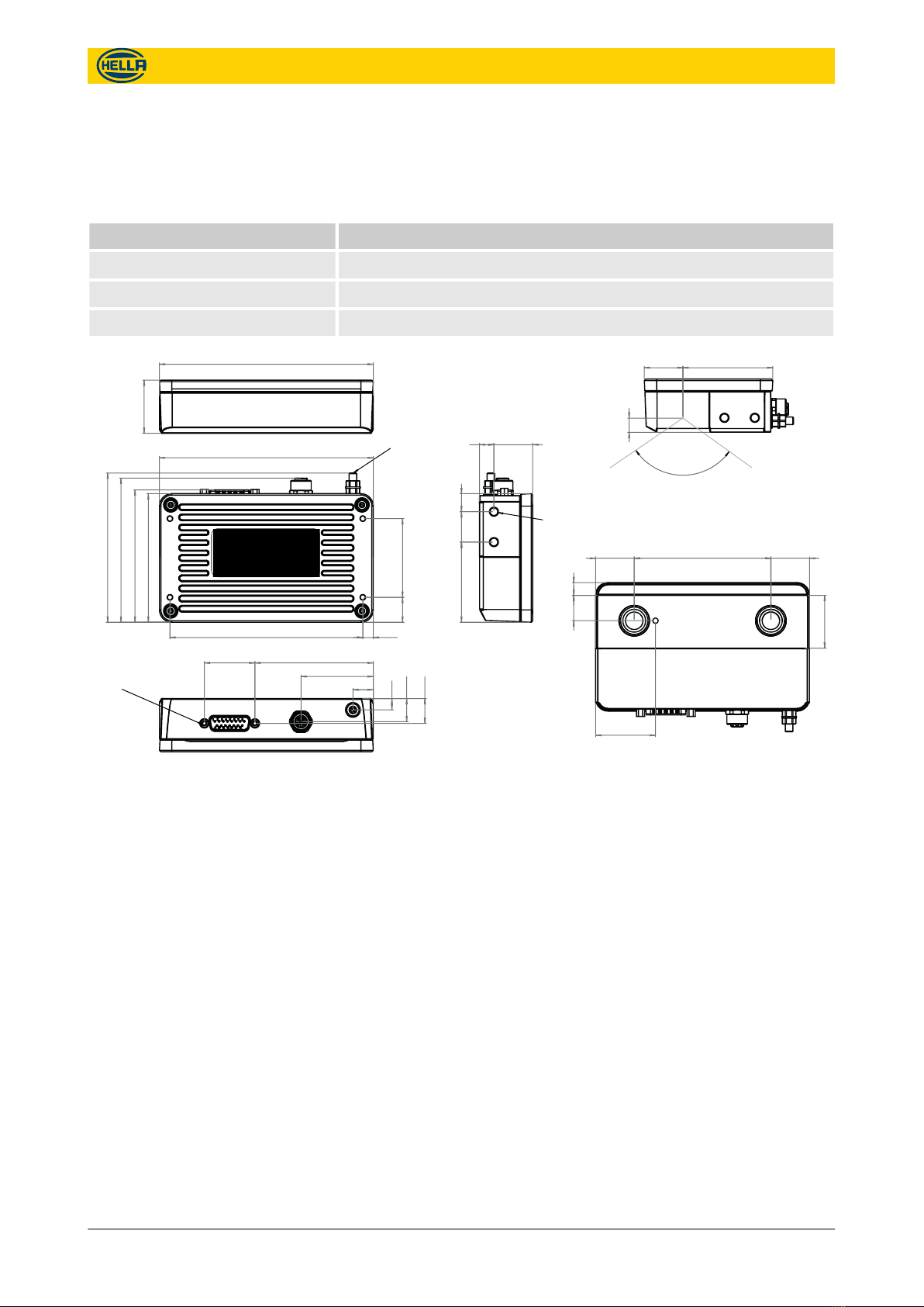
4 Technical data
4.1 Mechanical data
Category Description
Dimensions approx. 141 mm x 98 mm x 35 mm (see Fig. 11)
Weight 440 g
Material Aluminum
25.509.50
59.2025.40
110°
Cone of view
8.32
25.40 90 25.40
8.4016.70
34.70
39.40
140.80
(IEC60947-7-1)
2-4 Nm
Ground stud M5
16.40 51.80
98.20
94.82
87.10
84.60
127 6.90
4x M5 x 8
max 8 Nm
52.75 20 11.85
7.50
15.20
16.36
33.30
13.40
47.60
77.91
max 0.6 Nm
UNC4-40
35
140. 80
Fig. 11: Dimension drawing
APS-R, APS-R-PoE
Technical data
Mechanical data
09.06.2017 17
The reproduction, distribution and utilization of this document as well as the communication of its contents to others
without express authorization is prohibited. Offenders will be held liable for the payment of damages.
All rights reserved in the event of the grant of patent, utility model or design.

4.2 Hardware interface specifications
4.2.1 Ethernet
Pin no. Name Description
1 TD+ Transmit data +
2 RD+ Receive data +
3 TD- Transmit data -
4 RD- Receive data -
5 SHD Shield
Compatibility of APS-R-PoE and PoE switches
APS-R-PoE
Port M12 D-coded
(4 pins)
PoE Switch
Port M12 D-coded (4pins)
Port M12 X-coded (8pins)
Port RJ45
"Mode A", "Midspan",
"Phantom Feed"
Port RJ45
"Mode B", "Endspan",
"Spare wire feed"
Pin allocation
1
2
3
4
5
Fig. 12: M12 Ethernet interface
Technical data
Hardware interface specifications > Ethernet
18 09.06.2017 The reproduction, distribution and utilization of this document as well as the communication of its contents to others
without express authorization is prohibited. Offenders will be held liable for the payment of damages.
All rights reserved in the event of the grant of patent, utility model or design.

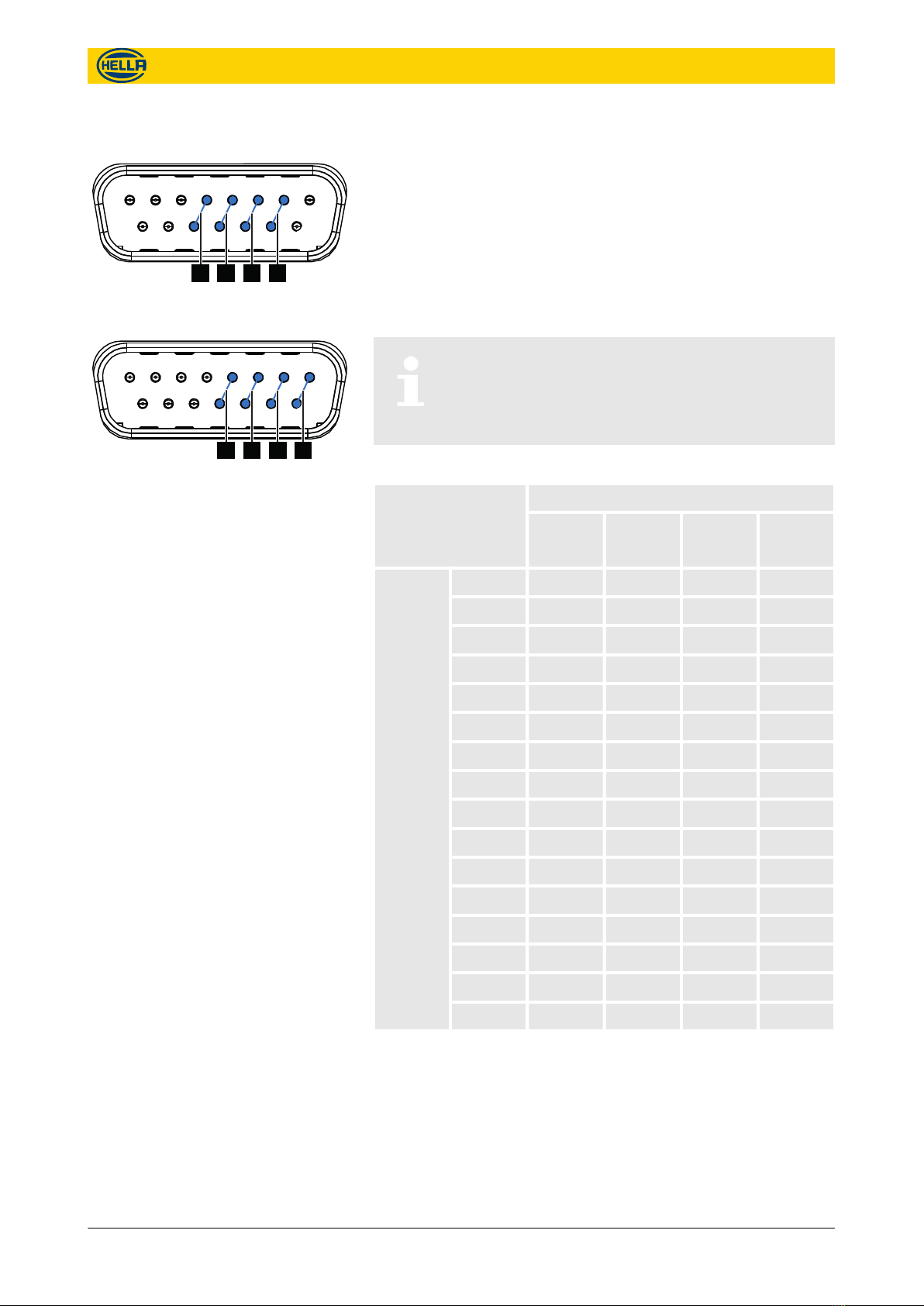
4.2.2 I/O-Port
Pin no. Name Description
1 Reset Reset Pin
(leave open, only required for correc-
tive maintenance)
2 OUT0 + Programmable output +, potential-
free
3 IN0 + Programmable input +, potential-free
(typically used for a door contact)
4 IN1 + Programmable input +, potential-free
(typically used for a door contact)
5 DID4 A Code jumper 4
(DID = "Door Identification")
6 DID3 A Code jumper 3
7 DID2 A Code jumper 2
8 DID1 A Code jumper 1
9 OUT0 - Programmable output -, potential-
free
10 IN0 - Programmable input -, potential-free
11 IN1 - Programmable input -, potential-free
12 DID4 B Code jumper 4
13 DID3 B Code jumper 3
14 DID2 B Code jumper 2
15 DID1 B Code jumper 1
Pin Allocation APS-R-PoE
1 2 3 4 5 6 7 8
9 10 11 12 13 14 15
Fig. 13: D-SUB I/O Interface
Technical data
Hardware interface specifications > I/O-Port
09.06.2017 19
The reproduction, distribution and utilization of this document as well as the communication of its contents to others
without express authorization is prohibited. Offenders will be held liable for the payment of damages.
All rights reserved in the event of the grant of patent, utility model or design.

Pin no. Name Description
1 Reset Reset Pin
(leave open, only required for correc-
tive maintenance)
2 OUT0 + Programmable output +, potential-
free
3 IN0 + Programmable input +, potential-free
(typically used for a door contact)
4 DID4 A Code jumper 4
(DID = "Door Identification")
5 DID3 A Code jumper 3
6 DID2 A Code jumper 2
7 DID1 A Code jumper 1
8 PWR + DC Power supply input +
9 OUT0 - Programmable output -, potential-
free
10 IN0 - Programmable input -, potential-free
11 DID4 B Code jumper 4
12 DID3 B Code jumper 3
13 DID2 B Code jumper 2
14 DID1 B Code jumper 1
15 PWR - DC Power supply input -
Pin Allocation APS-R
1 2 3 4 5 6 7 8
9 10 11 12 13 14 15
Fig. 14: D-SUB I/O Interface
Technical data
Hardware interface specifications > I/O-Port
20 09.06.2017 The reproduction, distribution and utilization of this document as well as the communication of its contents to others
without express authorization is prohibited. Offenders will be held liable for the payment of damages.
All rights reserved in the event of the grant of patent, utility model or design.
This manual suits for next models
1
Table of contents
Other Hella Accessories manuals

Hella
Hella C2 Setup guide

Hella
Hella APS-90 Manual

Hella
Hella SOLEYA Setup guide

Hella
Hella 8JB 007 242-011 User guide

Hella
Hella ELEGANZA Setup guide

Hella
Hella PM03 Setup guide

Hella
Hella PM07 protect Setup guide

Hella
Hella CLEO 5530 Setup guide

Hella
Hella CLEO 7030 Setup guide

Hella
Hella ONYX.WEATHER User manual


353B17 Installation and operating manual")


