manuals.online logo
Brands
  1. Home
  2. •
  3. Brands
  4. •
  5. Helvex
  6. •
  7. Plumbing Product
  8. •
  9. Helvex 313-38-4.8 User manual

Helvex 313-38-4.8 User manual

INSTALLATION GUIDE
GUÍA DE INSTALACIÓN
1-06-1191-4
ADVERTENCIA / WARNING
Agradecemos su elección por los productos HELVEX.
Estamos seguros de que su confiabilidad por el producto excederá sus más altas expectativas, cuya
funcionalidad, estética, durabilidad, respaldo integral y alta calidad le otorgarán plena satisfacción por años,
reflejando el compromiso con la calidad, innovación y el medio ambiente que forman parte de Helvex.
Thank you for choosing HELVEX products.
We are confident that the product reliably will exceed your highest expectations -This product's functionality,
aesthetics, durability, quality and support will grant you full satisfaction for years, thus reflecting Helvex's
commitment to quality, innovation and the environment.
Esta Guía de Instalación Aplica al Producto en Cualquier Acabado
This Installation Guide Applies to the Product in any Finishing
Hola soy Fluxy, te
ayudaré a instalar
tu producto.
Hi I'm Fluxy, I'll
help you to install
your product.
313-38-4.8
313-38-4.8
313-38-3.5
Cada metro de altura de
su producto a la base
del tinaco equivalen a
(0,1 kg/cm²) [1,42 PSI].
Every meter of height of
your product to the base
of the tube is equivalent
to (0,1 kg/cm²) [1,42
PSI].
Requerimientos de Instalación
Installation Requirements
Requerimientos de Instalación
Installation Requirements
Modelo / Model Mínima / Minimum Máxima / Maximum
kg/cm² PSI kPa kg/cm² PSI kPa
Para el correcto funcionamiento de éstos productos, se recomiendan las siguientes presiones:
For the correct operation of these products, the following pressures are recommended:
313-38-3.5
1,0 14,2 98,06 6,0 85,3 588,3
2,0 28,4 196,1 6,0 85,3 588,3
313-38-4.8
313-38-3.5
[email protected]
Original Spare Parts:
Consultancy and Technical
(52) 55 53 33 94 31
(52) 55 53 33 94 00
Refacciones Originales:
Asesoría y Servicio Técnico:
Ext. 5913, 5068 y 4815
Service:
(52) 55 53 33 94 21
[email protected]
www.refaccioneshelvex.com.mx
desarmador
phillips
screwdriver
cortador de tubo
pipe cutter
Dimensiones Recomendadas / Recommended Dimensions
1
Nota: La tubería debe ser de
Ø 32mm desde la alimentación.
Note: The pipe diameter should
be Ø1 ¼" from the supply line.
tubería de alimentación
Ø 32mm (no incluida)
Ø 1 ¼" supply pipe
(not included)
reducción campana de
Ø 32 a 25,4 mm (no incluida)
Ø 1 ¼" - 1" reducing coupling
(not included)
adaptador
(incluido)
adapter
(included)
tubo Ø 25,4 mm (no incluido)
Ø 1" pipe (not included)
cámara de aire con tubo de Ø 32 mm
air chamber with Ø1 ¼” pipe
tubo Ø 32 mm
(no incluido)
Ø 1 ¼” pipe
(not included)
60 cm
(23,6”)
Herramienta Incluida
/ Tools
llave inglesa teflón
adjustable
wrench
plumber´s
tape 5/64”allen
wrench
llave allen
5/64” fixing kit
kit de sujeción
taladro con
broca de Ø ¼”
drill with Ø ¼
drill bit
en el Producto
Included in the Product
lápiz
pencil
desarmador
slotted
screwdriver
de cruz plano
*El producto ya cuenta con la calibración del
sistema de tensado desde fábrica en el pedal,
para su funcionamiento.
*The product already has the calibration of the
tension system from the manufacture on the
padal, for its operation.
Para disminuir el riesgo de lesiones o daños a la propiedad, lea todas las instrucciones antes de instalar el
producto. Utilice gafas de seguridad. En obras de construcción, instalación, modificación, ampliación y
reparación deben cumplir con el reglamento de construcción y obras de su localidad. El producto ilustrado
puede sufrir cambios de aspecto como resultado de la mejora continua a la que está sujeto.
To reduce the risk of injury or property damage, please read all instructions before installing the product. Wear
safety glasses. For any construction, installation, alteration, estension or repair, comply to your local building
codes. The product illustration may vary in appearance to the actual product, as result of the continuous
improvement process it is subject to.
Recommended Tools and Materials
Herramienta y Materiales Recomendados /
Included in the Product
Artículos incluidos en
el Producto / Items
Fluxómetro de Pedal Expuesto para Taza Flux, Spud de 38 mm, 4,8 LPD
Exposed Pedal Flushometer for Flux Bowl, 1 ½” Spud, 1,26 GPF
Fluxómetro de Pedal Expuesto para Taza Flux, Spud de 38 mm, 3,5 LPD
Exposed Pedal Flushometer for Flux Bowl, 1 ½” Spud, 0,92 GPF
2
Componentes del Producto / Product Components
3
Desarme el fluxómetro. / Disassemble
the flushometer.
4
Instalación General / General Installation
válvula de
retención
stop valve
cuerpo armado
assembly body
Coloque la llave de retención y el adaptador (inlcuido) con respecto a la ubicación del
inodoro. / Place the stop valve and adapter (included) with respect to the location of the
toilet.
5
Nota: Después de recortar la camisa presente nuevamente la llave de retención
y verifique su longitud con respecto al spud del inodoro.
Note: After cutting the cover tube place again the stop valve and check its length
to spud to the toilet.
Sólo si la distancia A es mayor a 6
cm utilice la camisa y recórtela si
es necesario.
Only if the distance A is greater
than 6 cm using the cover tube and
cut it if necessary.
A
llave de
retención
stop valve
adaptador
(incluido)
adapter
(included)
chapetón
escutcheon
cortador de tubo
(no incluido)
pipe cutter
(not included)
camisa
cover tube
llave de
retención
stop valve
camisa
cover tube
22
11,1
(4,4”)
6 - 16 cm
(2,4” - 6,3”)
pared con
acabado final
finished wall
24,0 cm
(9,4”)
NPT
FFL
Spud
Ø 38 mm
(Nivel de Piso Terminado)
(Finished Floor Level)
* Medidas recomendadas.
* Recommended dimensions.
No. DESCRIPCIÓN
1 Cúpula
2 Émbolo
3 Rondana Vulcanizada
4 Anillo Presión Niple Extensión
5 O´ring
6 Válvula de Retención
7 Adaptador
8 Camisa
9 Chapetón
10 Accionador Armado
11 Abrazaderas
12 Tubo Flexible
13 Pedal
Empaques, tuercas spud 38 mm,
rondanas, chapetón spud 38 mm y
niple recto de 38 mm
14
DESCRIPTION
Cap
Piston
Vulcanized Washer
Locking Ring
O´ring
Stop Valve
Adapter
Cover Tube
Escutcheon
Assembly Actuator
Pipe Clamps
Flexible Tube
Pedal
3
1
2
12
4
5
6
8
10
11
Para spud de Ø 38 mm / For Ø 1 ½” spud
14
111
(4,4”)
Ø 38
(1,5”)
228,6
(9,0”)
VISTA FRONTAL
FRONT VIEW
Ø 38
(1,5”)
11
11
9
7
Medidas Generales / General Dimensions
43,9 cm
(17,3”)
Gaskets, 1 ½” spud nuts, friction rings,
1 ½" spud esutcheon and 1 ½" outlet tube.
13
313-38-3.5
Émbolo Naranja 3,5 LPD
0,92 GPF Orange Piston
313-38-4.8
Émbolo Verde 4,8 LPD
1,26 GPF Green Piston
adaptador
adapter
3
Solde el adaptador (incluido). / Weld the
adapter (included).
6
A: Longitud final.
A: Final lenght.
tubería de alimentación
Ø25 mm (no incluida)
Ø1" supply pipe
(not included)
pared con
acabado final
finished wall
adaptador
(incluido)
adapter
(included)
A
8
cuerpo armado
assembly body
cortador de tubo(no incluido)
pipe cutter (not included)
niple
outlet tube
Coloque el cuerpo armado y verifique la
distancia (B) y si es necesario recorte el
niple. / Place the assembly body and
check the distance (B) and if necessary
cut the outlet tube.
B
chapetón
escutcheon
llave de
retención
stop valve
camisa
cover tube
Inserte el chapetón con la camisa y
enrosque la llave de retención. / Insert
the escutcheon with the cover tube and
screw the stop valve.
7
Nota: La instalación puede ser izquierda o derecha.
Note: Left or right hand installation.
Arme el niple para spud. / Assembly the outlet tube to spud.
9
tuerca
nut
rondana
friction ring
empaque
gasket
empaque
gasket
rondana
friction ring
tuerca
nut
niple recto
de 38 mm
1 ½”
outlet tube
Mod.
313-38-3.5
313-38-4.8
Verifique el apriete del
spud. / Check the
tightness of the spud.
chapetón
escutcheon
spud
(no incluido)
(not included)
cuerpo armado
assembly body
Coloque el chapetón y enrosque el cuerpo armado sin apretar. /
Place the escutcheon and screw the assembly body loosely.
10 Coloque el niple armado. / Place the assembly outlet tube.
11
cuerpo
armado
assembly
body
llave de
retención
stop valve
niple
armado
assembly
outlet tube
Nota: Enrosque el niple armado, posteriormente apriete firmemente el cuerpo
armado a la llave de retención.
Note: Screw the assembly outlet tube, then firmly tighten the body assembly to stop
valve.
Verifique que las rondanas estén
bien colocadas. / Check that the
friction rings are properly installed.
12 Enrosque el accionador armado y ubique la posición del pedal
marcando en el piso los barrenos de la base y marcando en la
pared la ubicación de las abrazaderas. Finalmente barrene con
broca de 1/4" todas las marcas. / Screw the assembly actuator
and locate the pedal by marking on the floor the holes in the base
and marking on the wall the location of the pipe clamps. Finally
drill all marks with a 1/4" drill bit.
13 Inserte los taquetes al piso y enrosque los tornillos para fijar,
finalmente coloque los tapones. / Insert the anchors into the floor
and screw the screws to fix, finally place the plugs.
tapón
plug
tornillo
screw
taquete
anchor
pedal
pedal
NO sugerido
NOT suggested
Inserte los taquetes a la pared y enrosque los tornillos para fijar las abrazaderas. / Insert the anchors to the wall and screw the screws to fix the
pipe clamps.
14
NO sugerido
NOT suggested
4
Nota: NO hacer curvas
menores a 10 cm /
Note: DO NOT make
curves less than 10 cm
Nota: NO doblar resorte
a menos de 90° /
Note: DO NOT bend
spring less than 90 °
Nota: NO hacer curvas
menores a 10 cm /
Note: DO NOT make
curves less than 10 cm
Nota: NO doblar resorte
a menos de 90° /
Note: DO NOT bend
spring less than 90 °
accionador armado
assembly actuator
pedal
pedal
5
cúpula
cap
empaque
gasket
Coloque el empaque y enrosque la
cúpula. / Place the gasket and screw
the cap.
17
18 19 20
21 22 23
Abra la llave de retención para purgar. /
Open the stop valve to purge.
llave de
retención
stop valve
Cierre la llave de retención. / Close the
stop valve.
Desenrosque la cúpula y retire el
empaque. / Unscrew the cap and
remove the gasket.
cúpula
cap
empaque
gasket
Verifique que no existan residuos en
el interior del cuerpo y en la cúpula. /
Check that there is not waste inside
the body and the cap.
cúpula
cap
residuos
waste
Inserte el émbolo, el empaque y
enrosque la cúpula, apretando
firmemente. / Insert the piston, the
gasket and screw the cap, thigten
firmly.
cúpula
cap
empaque
gasket
émbolo
piston
Abra completamente la llave de
retención, coloque el tapón y accione 3
veces para estabilizar el funcionamiento,
permitiendo el ciclo completo entre
descarga en cada accionamiento. / Fully
open the stop valve, place the stop valve
cover and do 3 complete flushes to
stabilize the operation.
llave de
retención
stop valve
llave de
retención
stop valve
tapón
stop valve
cover
16
cúpula
cap
empaque
gasket
émbolo
piston
Desenrosque la cúpula y retire el
empaque y el émbolo. / Unscrew the
cap and remove the gasket and the
piston.
15 Retire el tapón y cierre la llave de
retención y abra el suministro general
del agua. / Remove the stop valve
cover and close the stop valve and
open the general water supply line.
llave de
retención
stop valve
tapón
stop valve
cover
313-38-3.5
Émbolo Naranja
Orange Piston
313-38-4.8
Émbolo Verde
Green Piston
313-38-3.5
Émbolo Naranja
Orange Piston
313-38-4.8
Émbolo Verde
Green Piston
6
Presione el pedal con el pie para generar una descarga del fluxómetro. / Press the pedal with the foot to generate a flushometer discharge.
25
Operación / Operation
313-38-3.5
Émbolo Naranja 3,5 LPD
0,92 GPF Orange Piston
313-38-4.8
Émbolo Verde 4,8 LPD
1,26 GPF Green Piston
Sistema de Seguridad / Security System
24 El fluxómetro cuenta con un sistema de seguridad anti robo: /The flushometer has an anti-theft security system:
Botón de seguridad / Safety button
Cierre el sistema general de agua.
1. Desenrosque la tuerca y retire el tapón. (Detalle 1), asegúrese de que la llave de retención esté abierta.
2. Coloque el tapón con o´ring como se muestra (Detalle 2), enrosque la tuerca en la llave de retención y abra el sistema general del agua. Así el sistema de alimentación del fluxómetro se
protege de que un externo pueda cerrar la llave de retención y proceder a un robo. Si la tuerca de la llave de retención se logra desenroscar, se generará una fuga proveniente del sistema
de alimentación general de agua.
Close the general water system.
1. Unscrew the nut and remove the cap. (Detail 1), make sure that the stop valve is open.
2. Place the cap with o'ring as shown (Detail 2) and screw the nut onto the stop valve y and open the water supply. Thus, the flushometer supply system protects itself from the fact that an
external one can close the stop valve and proceed with a theft. If the nut on the stop valve is unscrewed, a leak will be generated from the general water supply.
Para que el sistema de seguridad funcione, la alimentación general de agua al fluxómetro debe estar abierta.
In order for the safety system to work, the water supply to the flushometer must be open.
tuerca
nut
Sistema Activado
Activated System Sistema Desactivado
Deactivated System
Detalle 1
Detail 1
Detalle 2
Detail 2
llave de
retención
stop valve
Cierre la llave de retención y genere una descarga de agua para
liberar la presión en el cuerpo. / Close the stop valve and generates
a water discharge to release the pressure in the body.
26
Mantenimiento del Émbolo / Piston Maintenance
Periodo óptimo de mantenimiento preventivo del émbolo : cada 6 meses / Optimal preventive piston maintenance: every 6 months
cúpula
cap
empaque
gasket
émbolo
piston
Desenrosque la cúpula y retire el empaque y el émbolo. / Unscrew
the cap and remove the gasket and piston.
27
llave de
retención
stop valve
tapón
stop valve
cover
Verifique que el empaque cónico y la rondana no estén desgastados, límpielos o cámbielos si es necesario. Arme nuevamente. / Check the
tapered gasket and washer are not worn, clean or replace if necessary. Reassemble.
31
Retire el tapón y cierre la llave de retención. / Remove the stop
valve cover and close the stop valve.
29 30
Mantenimiento del Accionador / Actuator Maintenance
llave de
retención
stop valve
tapón
stop valve
cover
Desarme el émbolo, lave a chorro de agua y reemplace las piezas que tengan desgaste si es necesario, finalmente arme nuevamente. /
Disassemble the piston and wash with water and replace wear parts if necessary, finally reassemble.
28
tornillo
screw
rondana
washer
muesca asiento con perno
bolt seat
llantita vulcanizada
(verificar desgaste)
piston vulcanized tire
(check for wear)
(verificar desgaste)
rubber washer
(check for wear)
rondana de hule
émbolo macho
male piston
émbolo hembra
female piston
notch
Asegúrese que las muescas
estén limpias. / Make sure
the notch are clean.
resorte émbolo
spring piston
cúpula
cap
perno regulador
adjusting bolts
accionador
actuator
Desenrosque el accionador. / Unscrew the actuator.
rondana
washer
empaque
cónico
tapered gasket
7
313-38-3.5
Émbolo (naranja)
(orange) Piston
313-38-4.8
Émbolo (verde)
(green) Piston
Posibles Causas y Soluciones / Troubleshooting
Problema / Problem Causas / Causes Soluciones / Solutions
El émbolo del fluxómetro no es el correcto. / The flushometer
piston is not correct.
La llave de retención está parcialmente abierta. /
The stop valve is partially open.
La presión de operación no es la adecuada. /
The operating pressure is not adequate.
Verifique que el émbolo sea el correcto (Pág. 2, paso 3) . / Verify
that the piston is correct (Page 2, step 3)
Abra totalmente la llave de retención (Pág.5, paso 23).
Open fully the stop valve (Page 5, step 23).
Verifique que la presión mínima de operación sea la adecuada (Pág. 1).
/ Verify that the minimum operating pressure is correct (Page 1).
La llave de retención está cerrada.
/ The stop valve is closed.
Abra completamente la llave de retención (Pág. 5 paso 23).
/ Fully open the stop valve (Page 5 step 23)
Hay fuga en las conexiones.
/ There are leaks in the
connections.
La línea está obstruida.
/ The supply line is obstructed.
Verifique que la tubería sea la indicada (pag. 1 Dimensiones
recomendadas). /Verify that the pipe are as stated (page 1
Recommended dimensions)
No cierra el flujo o tarda
en cerrar. / The flow is not
closed or takes time to close.
La descarga es poca o nula.
/ The discharge is low or null.
El diámetro de la tubería no es la adecuada.
/ The diameter of the pipe is not adequate.
Las conexiones no están apretadas.
/ The connections are not tight.
Las rondanas están torcidas o mal colocadas.
/ The friction rings are bent or misplaced.
Apriete firmemente. / Tighten firmly.
Verifique que las rondanas esten colocadas correctamente
(Pág. 3, paso 9). / Verify that the friction rings are placed
correctly (Page. 3, step 9).
Acumulación de basura en el émbolo.
/ Debris in the piston.
Realice el mantenimiento del émbolo (Pág. 6, pasos 26, 27 y 28). /
Generate the maintenance (Page 6, steps 26, 27 and 28).
Verifique que haya buen flujo de agua retirando el émbolo y purgando
(Pág. 6 Mantenimiento del émbolo). / Check for good water flow removing
the piston and purging (Page 6 Piston Maintenance).
No existe flujo de agua al
accionar el pedal.
/ There is no water flow when
the pedal is operated.
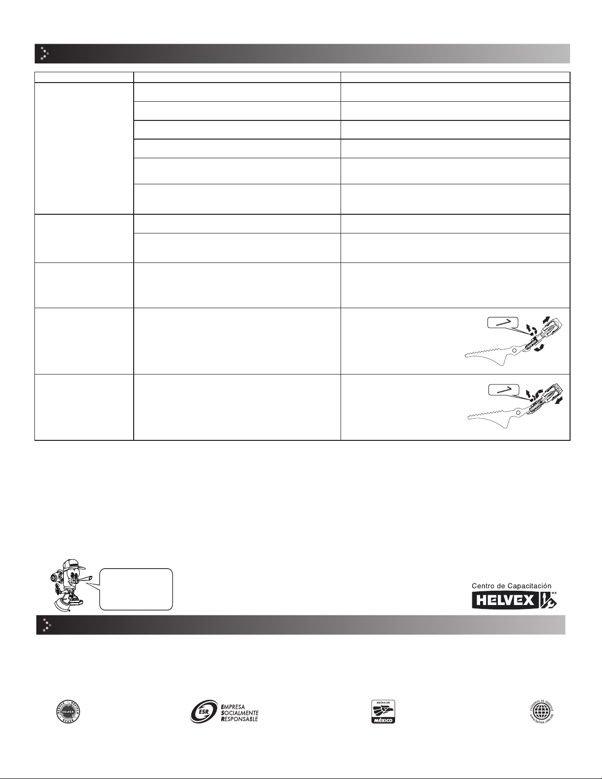
El pedal no presenta tensión. /
The pedal has no tension.
Ajustar hacia la condición máxima
para control de tensión de chicote.
Adjust to maximum condition to
control the whip cable tension.
El pedal presenta sensación de sobre tensado. /
The pedal has an over-stressed feeling.
Existe flujo de agua sin
accionar el pedal.
/ There is water flow without
pressing the pedal.
Ajustar hacia la condición mínima
para control de tensión de chicote.
Adjust to minimum condition to
control the whip cable tension.
Recomendaciones de Limpieza / Cleaning Recommendations
Enter our free
training courses.
Participa en nuestros
cursos gratuitos
de capacitación.
HELVEX, S. A. DE C. V. Calzada Coltongo # 293, Col. Industrial Vallejo, Alcaldía Azcapotzalco, C. P. 02300, Ciudad de México.
It is very important to follow the instructions below to preserve HELVEX products
finishings, shiny and in perfect conditions:
1. Use only water and a clean cloth.
2. Do not use fibers, powders, abrasives, or chemicals.
3. Do not use sharp objects to clean the finishings.
4. It is recommended to clean your device daily
Visit our websites www.helvex.com.mx for México and www.helvex.com
for the international market
Es muy importante seguir las siguientes instrucciones para conservar los
acabados de los productos HELVEX, con brillo y en perfecto estado:
1. Utilice únicamente agua y un paño limpio.
2. No utilice fibras, polvos, abrasivos, ni productos químicos.
3. No utilice objetos punzo-cortantes para limpiar los acabados.
4. Se recomienda realizar la limpieza de su producto diariamente.
Visite nuestras páginas www.helvex.com.mx para México y www.helvex.com
para el mercado internacional
In Guadalajara:
Contact:
In Monterrey:
En la Ciudad de México:
In Mexico City:
En Monterrey: En Guadalajara:
(52) 55 53 33 94 00
Ext. 5806, 5805 y 5804
33 36 19 01 13
Comunícate:
81 83 33 57 67
81 83 33 61 78

This manual suits for next models

1

Other Helvex Plumbing Product manuals

Helvex Kubica TR-036 User manual

Helvex

Helvex Kubica TR-036 User manual

Helvex SQUADRA E-711 User manual

Helvex

Helvex SQUADRA E-711 User manual

Helvex Premier H-3005 User manual

Helvex

Helvex Premier H-3005 User manual

Helvex UH-105-WOA User manual

Helvex

Helvex UH-105-WOA User manual

Helvex LAV MARCUS User manual

Helvex

Helvex LAV MARCUS User manual

Helvex 312-32 User manual

Helvex

Helvex 312-32 User manual

Helvex EP-94 User manual

Helvex

Helvex EP-94 User manual

Helvex H-8801 User manual

Helvex

Helvex H-8801 User manual

Helvex FORZA TV-304 User manual

Helvex

Helvex FORZA TV-304 User manual

Helvex Premier E-909 User manual

Helvex

Helvex Premier E-909 User manual

Helvex E-300-DX-EB User manual

Helvex

Helvex E-300-DX-EB User manual

Helvex PIURA PIU-200 User manual

Helvex

Helvex PIURA PIU-200 User manual

Helvex H3303-THD User manual

Helvex

Helvex H3303-THD User manual

Helvex Argos TV-296 User manual

Helvex

Helvex Argos TV-296 User manual

Helvex Nautilia E-924 User manual

Helvex

Helvex Nautilia E-924 User manual

Helvex Argos TV-296 User manual

Helvex

Helvex Argos TV-296 User manual

Helvex Nuva TV-200 User manual

Helvex

Helvex Nuva TV-200 User manual

Helvex C-69-S User manual

Helvex

Helvex C-69-S User manual

Helvex FC-110-38-3.5 User manual

Helvex

Helvex FC-110-38-3.5 User manual

Helvex LIQUIDA UTV-302 Manual

Helvex

Helvex LIQUIDA UTV-302 Manual

Helvex Tritón VCG-2 User manual

Helvex

Helvex Tritón VCG-2 User manual

Helvex Kúbica 14104 User manual

Helvex

Helvex Kúbica 14104 User manual

Helvex NAO WM User manual

Helvex

Helvex NAO WM User manual

Helvex TH-063 User manual

Helvex

Helvex TH-063 User manual

Popular Plumbing Product manuals by other brands

American Standard Laundry 7573.140 Specification sheet

American Standard

American Standard Laundry 7573.140 Specification sheet

Franke F5LT1010 Installation and operating instructions

Franke

Franke F5LT1010 Installation and operating instructions

Cobra Pro CP3020 Operational manual

Cobra Pro

Cobra Pro CP3020 Operational manual

IB RUBINETTERIE PURO 383 Fitting instructions

IB RUBINETTERIE

IB RUBINETTERIE PURO 383 Fitting instructions

Hewi S50.02.00001 Installation and operating instructions

Hewi

Hewi S50.02.00001 Installation and operating instructions

Hans Grohe Metropol 32520 Series Instructions for use/assembly instructions

Hans Grohe

Hans Grohe Metropol 32520 Series Instructions for use/assembly instructions

Speakman SE-700 Installation, maintenance & operating instructions

Speakman

Speakman SE-700 Installation, maintenance & operating instructions

Signature Hardware Boca Raton 948587 installation instructions

Signature Hardware

Signature Hardware Boca Raton 948587 installation instructions

Hans Grohe Croma 100 Duschpaneel 27105000 Installation

Hans Grohe

Hans Grohe Croma 100 Duschpaneel 27105000 Installation

Sanela SLUN 71PB Instructions for use

Sanela

Sanela SLUN 71PB Instructions for use

BELLOSTA THEO 0905 installation instructions

BELLOSTA

BELLOSTA THEO 0905 installation instructions

Moen 8210 Installation

Moen

Moen 8210 Installation

Franke AT3O0044 Installation and operating instructions

Franke

Franke AT3O0044 Installation and operating instructions

Speakman CPT-24400 instructions

Speakman

Speakman CPT-24400 instructions

Brizo T609 Series manual

Brizo

Brizo T609 Series manual

Kohler K-4108T Installation guides

Kohler

Kohler K-4108T Installation guides

SCHÜTTE 64800 installation instructions

SCHÜTTE

SCHÜTTE 64800 installation instructions

Moen TS93003 quick start guide

Moen

Moen TS93003 quick start guide

manuals.online logo
manuals.online logoBrands
  • About & Mission
  • Contact us
  • Privacy Policy
  • Terms and Conditions

Copyright 2025 Manuals.Online. All Rights Reserved.