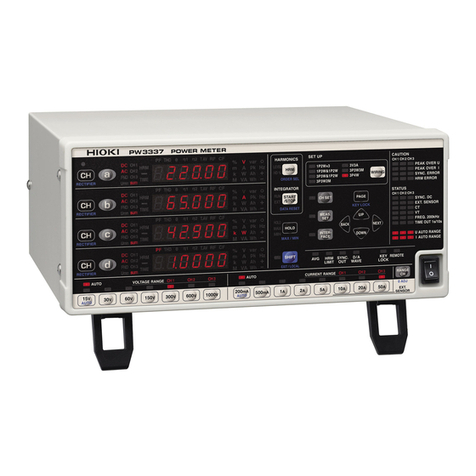
Hioki 3169-20 User manual

CLAMP ON POWER
INSTRUCTION MANUAL
3169-20/21
HiTESTER


i
Contents
1
2
3
4
5
6
7
8
9
10
11
APPX
IDX
Contents
Introduction .................................................................. 1
Standard Accessories and Options ..............................1
Safety Notes ................................................................ 4
Usage Notes ................................................................ 7
1 Overview 13
1.1 Product Overview .............................................13
1.2 Features ...........................................................14
2 Parts Names 17
2.1 Instrument Labels and Functions .....................18
2.2 Screen Names and Display Elements ..............22
2.2.1 Screen Configuration .........................................22
2.2.2 Common Display ...............................................23
2.2.3 On-Screen Indicators .........................................24
3 Measurement Preparations 25
3.1 Connection Procedure ......................................25
3.2 Connecting the Power Cord............................. 26
3.3 Connecting the Voltage Cords ......................... 27
3.4 Using a Clamp-On Sensor (Option) ................. 29
3.4.1 Clamp-On Sensor Specifications .......................29
3.4.2 Connecting a Clamp-on Sensor ........................31
3.5 Turning the Power On/Off ................................33

ii
Contents
4 Connecting to Lines to be Measured 35
4.1 Connection Procedure ......................................35
4.2 Connection Methods ........................................36
4.2.1 Displaying the Wiring Diagram ..........................36
4.2.2 Basic Wiring for Single-Circuit Measurement ....39
4.2.3 Wiring for Multiple-Circuit Measurement ...........45
4.2.4 Connection to a Line to Be Measured ...............48
4.2.5 Checking the Wiring ..........................................49
4.3 Measurement Range ........................................53
5 Setting Procedure 55
5.1 Setting Screen ..................................................55
5.2 Setting on the Measurement Setting Screen
(MEASUREMENT) ...........................................56
5.2.1 Setting the Wiring Method .................................57
5.2.2 Setting the Synchronization Method ..................59
5.2.3 Setting the Reactive-Power-Meter Method ........60
5.2.4 Setting the Display Average Times ...................62
5.2.5 Setting the Voltage Range ................................63
5.2.6 Setting the VT Ratio (PT Ratio) .........................64
5.2.7 Setting the Current Range .................................65
5.2.8 Setting the CT Ratio ..........................................66
5.2.9 Setting the Clamp-On Sensor ............................67
5.3 Setting on the Data Output Setting Screen
(DATA OUTPUT) .............................................. 68
5.3.1 Setting the Time-Series Measurement Start
Method ..............................................................69
5.3.2 Setting Time-Series Measurement Stop Method
...........................................................................71
5.3.3 Setting Interval ..................................................74
5.3.4 Setting Medium for Saving Data ........................75
5.3.5 Setting the Data File Name ...............................76
5.3.6 Setting Device to Be Connected to the RS-232C
77

iii
Contents
1
2
3
4
5
6
7
8
9
10
11
APPX
IDX
5.3.7 Setting the Medium to which the Screen is to be
Copied ...............................................................78
5.4 Setting on the Save/Print Items Setting Screen
(SAVE, PRINT ITEMS) .....................................79
5.4.1 Checking the number of output data items and
Storable Time ....................................................79
5.4.2 Setting Normal Measurement-Data Output Items
...........................................................................80
5.4.3 Setting Integrated power and Demand
Measurement-data Output Items .......................81
5.4.4 Setting Harmonic Measurement-data Output Items
...........................................................................82
5.5 Setting on the System Setting Screen ..............85
5.5.1 Setting the THD Calculation Method .................86
5.5.2 Setting the Harmonic Order for Display .............87
5.5.3 Setting the RS-232C ..........................................88
5.5.4 Setting the LCD Backlight ..................................89
5.5.5 Setting the Beep Sound ....................................90
5.5.6 Setting the ID No. ..............................................91
5.5.7 Setting the Clock ...............................................92
5.5.8 Setting the Language ........................................93
5.5.9 Displaying the Serial No. and Version ...............94
6 Measurement Method 95
6.1 Measuring the Voltage, Current, and Power
(Instantaneous Values) ....................................95
6.2 Measuring the Power of Each Phase
(Instantaneous values) .....................................97
6.3 Displaying a Waveform ....................................98
6.4 Measuring the Average, Maximum, and Minimum
Values ............................................................ 100
6.4.1 Displaying the Voltage, Current, and Power
(Average, Maximum, and Minimum Values) ....101
6.4.2 Displaying the Average, Maximum, and Minimum
Power Measurements of Each Phase .............102
6.5 Measuring Integrated power ...........................103

iv
Contents
6.6 Performing Demand Measurement ................ 104
6.7 Measuring Harmonic ...................................... 105
6.7.1 Displaying a Harmonic List ..............................105
6.7.2 Displaying a Harmonic Graph ..........................108
6.8 Displaying on a Zoom Screen ........................ 113
6.9 Holding Displayed Measurement Data ...........114
7 Loading and Saving Settings and Measured
Data 115
7.1 Types of Files ................................................. 115
7.2 Using a PC Card ............................................ 117
7.2.1 Selecting a PC Card ........................................117
7.2.2 Inserting and Removing the PC Card ..............118
7.3 File Operation ................................................. 119
7.3.1 Initializing (Formatting) the Internal Memory ..120
7.3.2 Initializing (Formatting) the PC Card ...............121
7.3.3 Saving a Setting File ........................................122
7.3.4 Loading a Setting File ......................................124
7.3.5 Deleting a File ..................................................126
7.3.6 Copying a File in the Internal Memory to a PC Card
128
7.4 Saving Measurement Data ............................. 129
7.4.1 Automatic Storage of Measurement Data .......129
7.4.2 Saving Measurement Data Manually ...............133
7.5 Copying Screen .............................................. 135
8 Using a Printer 137
8.1 Connecting the Printer .................................... 138
8.2 Setting the Printer ........................................... 140
8.2.1 Setting the Device to Be Connected to the
RS-232C ..........................................................140
8.2.2 Setting the RS-232C ........................................141

v
Contents
1
2
3
4
5
6
7
8
9
10
11
APPX
IDX
8.3 Automatic Output of Measurement Data to the
Printer ............................................................. 142
8.4 Copying a Screen to the Printer .....................144
9 Using the Instrument with a Computer 145
9.1 RS-232C Connection ..................................... 146
9.2 Setting the RS-232C ...................................... 148
10 Using the External Input/Output Terminal 151
10.1 Connecting the External Input/Output Terminal
........................................................................ 151
10.2 Functions of the External Input/Output Terminal
........................................................................ 152
10.3 Controlling Multiple Units of the 3169-20/21 .. 155
11 Using D/A Output (3169-21 only) 157
11.1 Connecting the D/A Output Terminal ............. 157
11.2 Setting D/A Output .........................................159
11.2.1 Setting D/A Output Items .................................159
11.2.2 Setting the Integrated Power Output Rate .......161
11.3 Response of Output .......................................162
11.4 Output Waveform ........................................... 164
12 Operations in the Event of Power Outage 169
13 Specifications 171
13.1 Formulae ........................................................ 180
13.2 Range Configuration and Accuracy by Clamp-On-
Sensor ............................................................ 184

vi
Contents
14 Maintenance and Service 189
14.1 Cleaning and Storage ..................................... 189
14.2 Repair and Servicing ...................................... 190
14.3 Instrument Disposal ........................................ 192
Appendix 195
Power Measurement by the 2 Power-Meter Method and
U3/I3 Measurement Theory (3P3W2M mode) .........195
Headers of Output Data ...........................................197
Harmonic Phase Angles .......................................... 201
Output Data .............................................................. 203
Error Messages ........................................................ 207

1
1
2
3
4
5
6
7
8
9
10
11
Introduction
Thank you for purchasing the HIOKI “3169-20/21 CLAMP ON
POWER HiTESTER”. To obtain maximum performance from the
product, please read this manual first, and keep it handy for future
reference.
• Refer to the Quick Start Manual provided with this device.
• For current input with this device, a clamp-on sensor (optional) is
required. For details, refer to the instruction manual for the
clamp-on sensor you are using.
Standard Accessories and Options
Checking the contents of the package
When you receive the product, inspect it carefully to ensure that no
damage occurred during shipping. In particular, check the accesso-
ries, panel switches, and connectors. If damage is evident, or if it
fails to operate according to the specifications, contact your dealer
or Hioki representative.
Power Cord Input Cord Label
9438-03 VOLTAGE CORD
1 set (4 cords)
(One each red, yellow, blue, and
black cords.)
3169-20/21
CLAMP ON POWER
HiTESTER
Quick Start Manual • Instruction Manual
• RS-232CInstruction
Manual
• CSV Conversion
Software (CD-R)
Instruction
Manual
9441 CONNECTION CABLE
(for D/A output, 3169-21 only)

2
Options
Clamps Voltage output type:
• 9660 CLAMP ON SENSOR (100 A rms rating)
• 9661 CLAMP ON SENSOR (500 A rms rating)
• 9667 FLEXIBLE CLAMP ON SENSOR
(5000 A rms rating)
• 9669 CLAMP ON SENSOR (1000 A rms rating)
• 9694 CLAMP ON SENSOR (5 Arms rating)
• 9695-02 CLAMP ON SENSOR (50 Arms rating)
• 9695-03 CLAMP ON SENSOR (100 Arms rating)
• 9290 CLAMP ON ADAPTER
(continuous 1000 A, up to 1500 A, CT ratio 10:1)
• 9219 CONNECTION CABLE (for 9695-02/03)
Interface • 9440 CONNECTION CABLE (for external input/output terminal)
• 9441 CONNECTION CABLE (for D/A output, 3169-21 only)
• 9612 RS-232C CABLE (for PC)
Printers • 9442 PRINTER (with 1 roll of thermally sensitized paper sup-
plied, with battery pack)
• 9443-01 AC ADAPTER (for printers) for Japan
• 9443-02 AC ADAPTER (for printers) for EU
• 9443-03 AC ADAPTER (for printers) for USA
• 1196 RECORDING PAPER (25 m, 10 rolls)
Transport
case • 9720-01 CARRYING CASE (The voltage cables and clamp-on
sensor are also housed in the case.)
(9720 CARRYING CASE)
Other
peripherals • 9626 PC Card 32 MB (32 MB compact Flash card + adapter)
• 9627 PC Card 64 MB (64 MB compact Flash card + adapter)
• 9726 PC Card 128 MB (128 MB compact Flash card + adapter)
• 9727 PC Card 256 MB (256 MB compact Flash card + adapter)
• 9728 PC Card 512 MB (512 MB compact Flash card + adapter)
Software • 9625 POWER MEASUREMENT SUPPORT SOFTWARE
(PC application software)

3
1
2
3
4
5
6
7
8
9
10
11
Before using the 3169-20/21
• Before using the product the first time, verify that it operates nor-
mally to ensure that the no damage occurred during storage or
shipping. If you find any damage, contact your dealer or Hioki
representative.
• Before using the product, make sure that the insulation on the
9438-03 VOLTAGE CORD is undamaged and that no bare con-
ductors are improperly exposed. Using the product in such con-
ditions could cause an electric shock, so contact your dealer or
Hioki representative for repair.
Shipping precautions
Use the original packing materials when reshipping the product, if
possible.

4
Safety Notes
Safety Symbols
This manual contains information and warnings essential for safe
operation of the product and for maintaining it in safe operating
condition. Before using the product, be sure to carefully read the
following safety notes.
This product is designed to conform to IEC 61010 Safety
Standards, and has been thoroughly tested for safety prior
to shipment. However, mishandling during use could result
in injury or death, as well as damage to the product. Be cer-
tain that you understand the instructions and precautions in
the manual before use. We disclaim any responsibility for
accidents or injuries not resulting directly from product
defects.
In the manual, the symbol indicates particularly
important information that the user should read before
using the product.
The symbol printed on the product indicates that the
user should refer to a corresponding topic in the manual
(marked with the symbol) before using the relevant
function.
Indicates AC (Alternating Current).
Indicates the ON side of the power switch.
Indicates the OFF side of the power switch.

5
1
2
3
4
5
6
7
8
9
10
11
The following symbols in this manual indicate the relative impor-
tance of cautions and warnings.
Other Symbols
Accuracy We define measurement tolerances in terms of f.s. (full scale), rdg.
(reading) and dgt. (digit) values, with the following meanings:
f.s. (maximum display value or scale length)
The maximum displayable value or the full length of the scale.
This is usually the maximum value of the currently selected range.
rdg. (reading or displayed value)
The value currently being measured and indicated on the measur-
ing product.
dgt. (resolution)
The smallest displayable unit on a digital measuring product, i.e.,
the input value that causes the digital display to show a "1".
Indicates that incorrect operation presents an
extreme hazard that could result in serious injury or
death to the user.
Indicates that incorrect operation presents a signifi-
cant hazard that could result in serious injury or
death to the user.
Indicates that incorrect operation presents a possi-
bility of injury to the user or damage to the product.
Advisory items related to performance or correct
operation of the product.
Indicates the prohibited action.
❖Indicates the reference.
Indicates quick references for operation and reme-
dies for troubleshooting.
*Indicates terminology explained at the bottom of
the page.

6
Measurement categories (Overvoltage categories)
This product conforms to the safety requirements for CAT III mea-
surement products.
To ensure safe operation of measurement products, IEC 61010
establishes safety standards for various electrical environments,
categorized as CAT I to CAT IV, and called measurement catego-
ries. These are defined as follows.
Higher-numbered categories correspond to electrical environments
with greater momentary energy, so a measurement product
designed for CAT III environments can endure greater momentary
energy than one designed for CAT II. Using a measurement prod-
uct in an environment designated with a higher-numbered category
than that for which the product is rated could result in a severe
accident, and must be carefully avoided.
Never use a CAT I measuring product in CAT II, III, or IV environ-
ments.
The measurement categories comply with the Overvoltage Cate-
gories of the IEC60664 Standards.
CAT I Secondary electrical circuits connected to an AC electrical out-
let through a transformer or similar device.
CAT II Primary electrical circuits in equipment connected to an AC
electrical outlet by a power cord (portable tools, household ap-
pliances, etc.)
CAT III Primary electrical circuits of heavy equipment (fixed installa-
tions) connected directly to the distribution panel, and feeders
from the distribution panel to outlets.
CAT IV The circuit from the service drop to the service entrance, and to
the power meter and primary overcurrentprotection device (dis-
tribution panel).

7
1
2
3
4
5
6
7
8
9
10
11
Usage Notes
Follow these precautions to ensure safe operation and to obtain
the full benefits of the various functions.
To avoid electric shock
• Do not allow the product to get wet, and do not use it when
your hands are wet.
• When measuring live lines, wear appropriate protective
gear, such as insulated rubber gloves, boots and a safety
helmet.
• Before turning the product on, make sure the source volt-
age matches that indicated on the product's power connec-
tor. Connection to an improper supply voltage may damage
the product and present an electrical hazard.
• To avoid electric shock and ensure safe operation, connect
the power cable to a grounded (3-contact) outlet.
• Do not use the product where it may be exposed to corro-
sive or combustible gases. The product may be damaged
or cause an explosion.
AC 100 V
to 240 V
Do not touch with
bare hands.
Do not get wet.
Check the voltage.

8
• This product is designed for indoor use, and operates reliably
from 0°C to 40°C.
• Do not store or use the product where it could be exposed to
direct sunlight, high temperature or humidity, or condensation.
Under such conditions, the product may be damaged and insu-
lation may deteriorate so that it no longer meets specifications.
• This product is not designed to be entirely water- or dust-proof.
To avoid damage, do not use it in a wet or dusty environment.
• Do not use the product near a device that generates a strong
electromagnetic field or electrostatic charge, as these may
cause erroneous measurements.
Setting up the 3169-20/21
Avoid the follow-
ing:
Direct
sunlight
High temper-
ature
High humidit
y
Dust
Electomagnetic
radiation
Corrosive or
explosive gases
• To avoid damage to the product, protect it from vibration or
shock during transport and handling, and be especially careful to
avoid dropping.
• Be careful to avoid dropping the clamps or otherwise subjecting
them to mechanical shock, which could damage the mating sur-
faces of the core and adversely affect measurement.
Handling this device

9
1
2
3
4
5
6
7
8
9
10
11
Connect the clamp-on sensors or voltage cords to the instru-
ment first, and then to the active lines to be measured.
Observe the following to avoid electric shock and short cir-
cuits.
• To avoid short circuits and potentially life-threatening haz-
ards, never attach the clamp to a circuit that operates at
more than the maximum rated voltage to earth (9660: 300
VAC, 9661: 600 VAC, 9667: 1000 VAC, 9669: 600 VAC, 9694:
300 VAC, 9695-02/03: 300 VAC), or over bare conductors.
• Clamp sensor and voltage cable should only be connected
to the secondary side of a breaker, so the breaker can pre-
vent an accident if a short circuit occurs. Connections
should never be made to the primary side of a breaker,
because unrestricted current flow could cause a serious
accident if a short circuit occurs.
• Do not allow the voltage cable clips to touch two wires at
the same time. Never touch the edge of the metal clips.
• Use only the supplied 9438-03 VOLTAGE CORD to connect
the product input terminals to the circuit to be tested.
• When the clamp sensor is opened, do not allow the metal
part of the clamp to touch any exposed metal or to short
across two lines, and do not use over bare conductors.
• The current input terminals of the 3169-20/21 are not insulated.
To avoid the risk of electric shock, only use the specified
optional clamp-on sensor.
Using the clamp-on sensors and voltage

10
• Keep in mind that, in some cases, conductors to be measured
may be hot.
• To avoid damaging the power cord, grasp the plug, not the cord,
when unplugging the cord from the power outlet.
• To avoid damaging the voltage cords or clamp sensor cables, do
not bend or pull near their ends.
• Avoid stepping on or pinching the cable, which could damage
the cable insulation.
• Keep the cables well away from heat sources, as bare conduc-
tors could be exposed if the insulation melts.
• When disconnecting the BNC connector, be sure to release the
lock before pulling off the connector. Forcibly pulling the connec-
tor without releasing the lock, or pulling on the cable, can dam-
age the connector.
• Failure to fasten the connectors properly may result is sub-spec-
ification performance or damage to the equipment.
Handling the cords
Maximum input voltage and maximum rated voltage
to earth
• The maximum input voltage of the product is 780 Vrms,
1103 V peak. Do not measure the voltage exceeding that. It
causes the personal injury as well as damages the product.
• The maximum rated voltage to earth of the product is 600
Vrms. Do not measure the voltage to earth exceeding that.
It causes the personal injury as well as damages the prod-
uct.
• The maximum rated voltage to earth of clamp sensor
depends on the type of clamp sensor used.
To avoid electric shock, refer to the instruction manual of a
clamp sensor used.
Input

11
1
2
3
4
5
6
7
8
9
10
11
• To avoid damage to the product, do not short-circuit the output
terminal and do not input voltage to the output terminal.
• Voltage input terminals U1, U2, and U3are common to the N ter-
minal and are not insulated. To avoid the risk of electric shock,
do not touch the terminals.
• Note that the product may be damaged if current or voltage
exceeding the selected measurement range is applied for a long
time
• When the power is turned off, do not apply voltage or current to
the voltage input terminals or clamp sensor. Doing so may dam-
age the product.
• To prevent damage to the instrument and sensor, never connect
or disconnect a sensor while the power is on, or while the sensor
is clamped around a conductor.
• When the voltage or current for the power line being measured
exceeds the maximum input for this device, use an external
VT(PT) or CT.
• When using an external VT(PT) or CT, make sure you use a
device with a minimal phase difference. By setting the VT(PT)
or CT ratio, you can read measurement values directly.
Using VT(PT) and CT

12
• To ensure measurements are precise, warm up the device for
at least 30 minutes after plugging it in.
• This device is designed to measure commercial power lines
with a frequency of 50 or 60 Hz. It cannot measure power lines
of other frequencies or power lines where the waveforms are
controlled using an inverter.
• This device cannot measure power lines with superposed
direct current.
• This device uses algorithms to measure values for input volt-
age and current waveforms using (see the specifications). On
devices using different operation principles or algorithms differ,
differences in measurement values may result.
• The voltage and current measurements will be reduced to zero
when inputs are less than 0.4% of the measurement range.
When the voltage or current is zero, the active power, reactive
power, and apparent power measurements will be reduced to
zero and the power factor will be treated as invalid data.
Measurement values
Other manuals for 3169-20
3
This manual suits for next models
1
Table of contents
Other Hioki Measuring Instrument manuals

Hioki
Hioki 8846 User manual

Hioki
Hioki 9014 User manual

Hioki
Hioki SM-8216 User manual

Hioki
Hioki PW3198 User manual

Hioki
Hioki IM7580A-1 Use and care manual

Hioki
Hioki MR8847-51 User manual

Hioki
Hioki PQ3198 User manual

Hioki
Hioki PW3335 User manual

Hioki
Hioki L2002 User manual

Hioki
Hioki CM3286-01 User manual

Hioki
Hioki 9290-10 User manual

Hioki
Hioki 9465-10 User manual

Hioki
Hioki 3664 User manual

Hioki
Hioki SM7420 User manual

Hioki
Hioki TM6102 User manual

Hioki
Hioki RM3545 User manual

Hioki
Hioki PW3390 User manual

Hioki
Hioki 3551 User manual

Hioki
Hioki 9651 User manual

Hioki
Hioki Memory HiCorder MR6000 User manual