manuals.online logo
Brands
  1. Home
  2. •
  3. Brands
  4. •
  5. Hioki
  6. •
  7. Measuring Instrument
  8. •
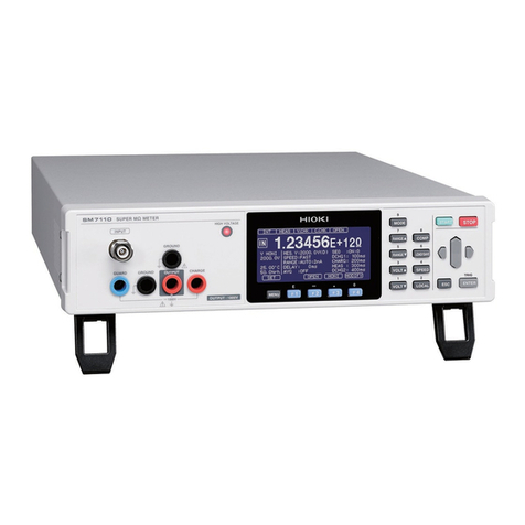
  9. Hioki PW3336-01 User manual

Hioki PW3336-01 User manual

Part names
Switches the display channel
(when in the shift state,
changes the rectifier).
Switches display parameters.
Displays measured values
and settings.
HRM: switches to the harmonic display.
START/STOP: Starts and stops integration; resets integrated values.
HOLD: Switches between the hold, maximum value, and minimum
value displays.
SHIFT: Press to access functions shown in blue.
POWER switch
Warning display lamps
(for each channel)
Switches the voltage range. Switches the current range. Switches the voltage and current
range channel (applies to both
voltage and current ranges).
Status display lamps
(for each channel)
Function settings
PW3336
PW3336-01, PW3336-02, PW3336-03
PW3337
PW3337-01, PW3337-02, PW3337-03
POWER METER
Measurement Guide
June 2013 Edition 1 Printed in Japan
PW3336A984-00 13-06H
Thank you for purchasing the HIOKI PW3336, PW3336-01, PW3336-02,
PW3336-03, PW3337, PW3337-01, PW3337-02, or PW3337-03 Power
Meter. This Measurement Guide introduces basic measurement methods
to individuals using the instrument for the first time. Be sure to review the
Instruction Manual before using the instrument.
1. Connecting the instrument
Example 1: 1P2W Before connecting the instrument, read “Operating Precautions” in
the Instruction Manual carefully.
Inverter
Power supply
Wiring diagram
CH(3)
Example 2: 3V3A
Motor
Inverter
Power
supply
Wiring diagram
CH(3) CH(1)CH(2)
2. Turning on the instrument
: Power ON
21 Connect the power cord. Turn on the POWER switch.
Do not activate input to the instrument before it has been turned on.
3. Selecting the wiring mode
Display Description
1P2W×3
(PW3336: 1P2W×2) Allows you to measure three 1-phase/2-
wire circuits. (PW336: Allows you to
measure two such circuits.)
1P3W&1P2W
(PW336: 1P3W only)
Measures a 1-phase/3-wire circuit with
CH1 and CH2. The PW3337 can simul-
taneously measure a 1-phase/2-wire
circuit with CH3.
3P3W&1P2W
(PW336: 3P3W only)
Measures a 3-phase/3-wire circuit with
CH1 and CH2 and measures active
power using the two-power-meter
method. The PW3337 can simultane-
ously measure a 1-phase/2-wire circuit
with CH3.
Display Description
3P3W2M
Measures a 3-phase/3-wire circuit with CH1 and CH2 and
measures active power using the two-power-meter
method. Calculates line voltage and phase current, which
are not actually measured, using vector calculations and
displays the result as the CH3 voltage and current.
3V3A Measures a 3-phase/3-wire circuit with connections for all
line voltages and phase currents and measures the
active power using the two-power-meter method.
3P3W3M Measures a 3-phase/3-wire circuit. Uses the same con-
nections as the 3V3A wiring mode but converts line volt-
ages into phase voltages by means of vector calculations
and displays the results.
3P4W Measures a 3-phase/4-wire circuit.
Press to select the wiring mode.
Display Description
VVoltage (U)
ACurrent (I)
WActive power (P)
VA Apparent power (S)
var Reactive power (Q)
PF Power factor (λ)
°Phase angle ()
V, Hz or
A, Hz Frequency (f)
Wh, + Positive direction Wh
Wh, - Negative direction Wh
Wh Total Wh
4. Selecting the display
Press to light up the blue lamp before setting functions shown in blue underneath
the keys.
Display Description
Ah, + Positive direction Ah
Ah, - Negative direction Ah
Ah Total Ah
TIME Integration time
V, pk Voltage waveform peak value
A, pk Current waveform peak value
η1 or η2Efficiency (η)
CF, %, V Voltage crest factor
CF, %, A Current crest factor
T.AV, W Time average active power
T.AV, A Time average current
RF, %, V Voltage ripple rate
Shift state
Select the parameters to display by pressing the parameter key.
Display Description
CH1 Lights up when displaying CH1 measured values.
CH2 Lights up when displaying CH2 measured values.
CH3 Lights up when displaying CH3 measured values.
sum Lights up when displaying measured values for
the sum of the selected display parameters when
using a wiring mode other than 1P2W.
Display Description
AC+DC AC + DC measurement; display of true RMS values for
both voltage and current
AC+DC
Umn
AC + DC measurement; display of mean value rectified
RMS converted values for voltage and true RMS values
for current
DC DC measurement; display of the DC component only
AC AC measurement; display of the AC component only
FND Display of the fundamental wave component from harmonic
measurement
Select the rectifier by pressing the CH key while holding
down the SHIFT key. Press the CH key to select the channel to display.
Display Description
RF, %, A Current ripple rate
THD, %, V Total harmonic voltage distortion
THD, %, A Total harmonic current distortion
FND, θ, V, ° Inter-channel voltage fundamental
wave phase difference
FND, θ, A, ° Inter-channel current fundamental
wave phase difference
HRM, V, LEVEL Harmonic voltage RMS value
HRM, A, LEVEL Harmonic current RMS value
HRM, W, LEVEL Harmonic active power RMS value
HRM, %, V, HD% Harmonic voltage content percentage
HRM, %, A, HD% Harmonic current content percentage
HRM, %, W, HD% Harmonic active power content
percentage
5. Selecting the voltage and current ranges
To select auto-range operation,
set after pressing .
The lamp for the selected range key will light up, and the display value will correspond to the range.
Voltage range Current range
Example: Voltage range: CH1, 300 V; current range: CH1, 20 A
Switches the channel for which the
range is being set (applies to both
voltage and current ranges).
2 Integration will start, and the RUN lamp will light up.
6. Performing integration
Integration is performed to measure the amount of power consumed in the set amount of time. In the example shown, the
integration time has been set to 24 hours.
Performing integration Stopping integration
1 Press . 2 Integration will stop, and the RUN lamp will flash.
1 Press while the RUN lamp is lit up.
Troubleshooting
While integration is being performed (the RUN lamp is lighting) or stopped (the RUN lamp is flashing), range, wiring
mode or other settings cannot be changed. To change settings or perform functions, follow the procedure described
below. Integrated value will be reset by this operation.
Procedure
If integration is stopped (if the RUN lamp is flashing), skip to Step 2.
1Press to stop integration.
The RUN lamp, which had been lit up, will start flashing.
2Press to place the instrument in the shift state.
The blue lamp will light up.
3Press .
The RUN lamp will turn off, and integrated values will be reset.
You can now change settings.
* Wiring mode, current input method, frequency measurement range (zero-cross filter), timeout, integration time, synchronization
source, VT ratio, CT ratio, harmonic analysis order upper limit value, zero-adjustment (can be performed while integration is
stopped)
If the instrument displays an error, see “Troubleshooting” in the instruction manual (for example , etc.).
If an error is being displayed
Even if the keys are pressed, no settings can be changed ( is displayed).
?
7. Turning off the instrument
: Power OFF
Once measurement is complete, turn off the
instrument and disconnect connection cables
and other wiring.
Turn off the POWER switch.

Other manuals for PW3336-01

1

This manual suits for next models

7

Other Hioki Measuring Instrument manuals

Hioki 3196 User manual

Hioki

Hioki 3196 User manual

Hioki LR8450 User manual

Hioki

Hioki LR8450 User manual

Hioki CM3286 User manual

Hioki

Hioki CM3286 User manual

Hioki RM3545 User manual

Hioki

Hioki RM3545 User manual

Hioki IM3536 User manual

Hioki

Hioki IM3536 User manual

Hioki CM4001 User manual

Hioki

Hioki CM4001 User manual

Hioki CHT3548 User manual

Hioki

Hioki CHT3548 User manual

Hioki 7015 User manual

Hioki

Hioki 7015 User manual

Hioki CT7631 User manual

Hioki

Hioki CT7631 User manual

Hioki CM4375 User manual

Hioki

Hioki CM4375 User manual

Hioki LR8450 User manual

Hioki

Hioki LR8450 User manual

Hioki HiTester 3443-01 User manual

Hioki

Hioki HiTester 3443-01 User manual

Hioki 3506-10 Parts list manual

Hioki

Hioki 3506-10 Parts list manual

Hioki 8870-20 User manual

Hioki

Hioki 8870-20 User manual

Hioki FT6380 User manual

Hioki

Hioki FT6380 User manual

Hioki CM3289 User manual

Hioki

Hioki CM3289 User manual

Hioki FT6381 User manual

Hioki

Hioki FT6381 User manual

Hioki MEMORY HiCORDER MR8847-01 User manual

Hioki

Hioki MEMORY HiCORDER MR8847-01 User manual

Hioki 3196 Instruction manual

Hioki

Hioki 3196 Instruction manual

Hioki CM3286 User manual

Hioki

Hioki CM3286 User manual

Hioki IM3533-01 Use and care manual

Hioki

Hioki IM3533-01 Use and care manual

Hioki FT3424 User manual

Hioki

Hioki FT3424 User manual

Hioki 2331-20 User manual

Hioki

Hioki 2331-20 User manual

Hioki RM9010-01 User manual

Hioki

Hioki RM9010-01 User manual

Popular Measuring Instrument manuals by other brands

LMI RFP Series instruction manual

LMI

LMI RFP Series instruction manual

Hanna Instruments HI 9033 instruction manual

Hanna Instruments

Hanna Instruments HI 9033 instruction manual

IDEAL 61-744 instruction manual

IDEAL

IDEAL 61-744 instruction manual

Tektronix Keithley SourceMeter 2470 quick start guide

Tektronix

Tektronix Keithley SourceMeter 2470 quick start guide

Rosemount 2130 Reference manual

Rosemount

Rosemount 2130 Reference manual

JUMO DI ECO operating instructions

JUMO

JUMO DI ECO operating instructions

DeWalt DW089 instruction manual

DeWalt

DeWalt DW089 instruction manual

Emerson Aventics R412018223 manual

Emerson

Emerson Aventics R412018223 manual

TaiDoc L1 owner's manual

TaiDoc

TaiDoc L1 owner's manual

Mini Radio Solutions miniVNA Reference manual

Mini Radio Solutions

Mini Radio Solutions miniVNA Reference manual

radiance RT818/E product manual

radiance

radiance RT818/E product manual

Vitrek 944i operating & maintenance manual

Vitrek

Vitrek 944i operating & maintenance manual

Extech Instruments MA410T user guide

Extech Instruments

Extech Instruments MA410T user guide

AST P-GM+ user manual

AST

AST P-GM+ user manual

Task Force Tips BLITZFIRE Series Instruction for operation and maintenance

Task Force Tips

Task Force Tips BLITZFIRE Series Instruction for operation and maintenance

Fluke Calibration 9190A Getting started

Fluke Calibration

Fluke Calibration 9190A Getting started

Itm SCALE MASTER CLASSIC 6020 user guide

Itm

Itm SCALE MASTER CLASSIC 6020 user guide

Trotec BA30WP operating manual

Trotec

Trotec BA30WP operating manual

manuals.online logo
manuals.online logoBrands
  • About & Mission
  • Contact us
  • Privacy Policy
  • Terms and Conditions

Copyright 2025 Manuals.Online. All Rights Reserved.