°
Warranty
Warranty malfunctions occurring under conditions of normal use
in conformity with the Instruction Manual and Product Precau-
tionary Markings will be repaired free of charge. This warranty
is valid for a period of one (1) year from the date of purchase.
Please contact the distributor from which you purchased the
product for further information on warranty provisions.
Introduction
Thank you for purchasing the HIOKI Model 9272-05 and 9272-
10 CLAMP ON SENSOR. To obtain maximum performance
from the device, please read this manual first, and keep it handy
for future reference.
Initial Inspection
When you receive the device, inspect it carefully to ensure that
no damage occurred during shipping. In particular, check the
accessories, panel switches, and connectors. If damage is evi-
dent, or if it fails to operate according to the specifications, con-
tact your dealer or Hioki representative.
This manual contains information and warnings essential for
safe operation of the device and for maintaining it in safe oper-
ating condition. Before using it, be sure to carefully read the fol-
lowing safety precautions.
Safety Symbols
The following symbols in this manual indicate
tance of cautions and warnings.
Other Symbol
Measurement categories
This device complies with CAT III safety requirements.
To ensure safe operation of measurement devices, IEC 61010 es-
tablishes safety standards for various electrical environments, cat-
egorized as CAT II to CAT IV, and called measurement categories.
CAT II: Primary electrical cir-
cuits in equipment
connected to an AC
electrical outlet by a
power cord (portable
tools, household
appliances, etc.)
CAT II covers directly
measuring electrical
outlet receptacles.
CAT III:Primary electrical circuits of heavy equipment (fixed installa-
tions) connected directly to the distribution panel, and feeders
from the distribution panel to outlets.
CAT IV:The circuit from the service drop to the service entrance, and
to the power meter and primary overcurrent protection device
(distribution panel).
Using a measurement device in an environment designated with a
higher-numbered categorythan thatfor whichthedeviceisrated could
result in a severe accident, and must be carefully avoided.Use of a
measurement instrument that is not CAT-rated in CAT II to CAT IV
measurement applications could result in a severe accident, and must
be carefully avoided.
Instrument Installation
Operating temperature and humidity: 0 to 50°C, 80%RH or less (non-condensation)
Follow these precautions to ensure safe operation and to obtain
the full benefits of the various functions.
The 9272-05 and 9272-10 was developed for to provide a 20 A,
200 A clamp sensor. Together with the power meter, the 9272-
10 makes it possible to measure alternating current in live pow-
er lines without cutting into the lines.
The sensor features excellent amplitude-frequency response
and phase-frequencyresponse, and is easy to connect anduse.
Its versatility will find application in a wide variety of fields deal-
ing with current and power measurement.
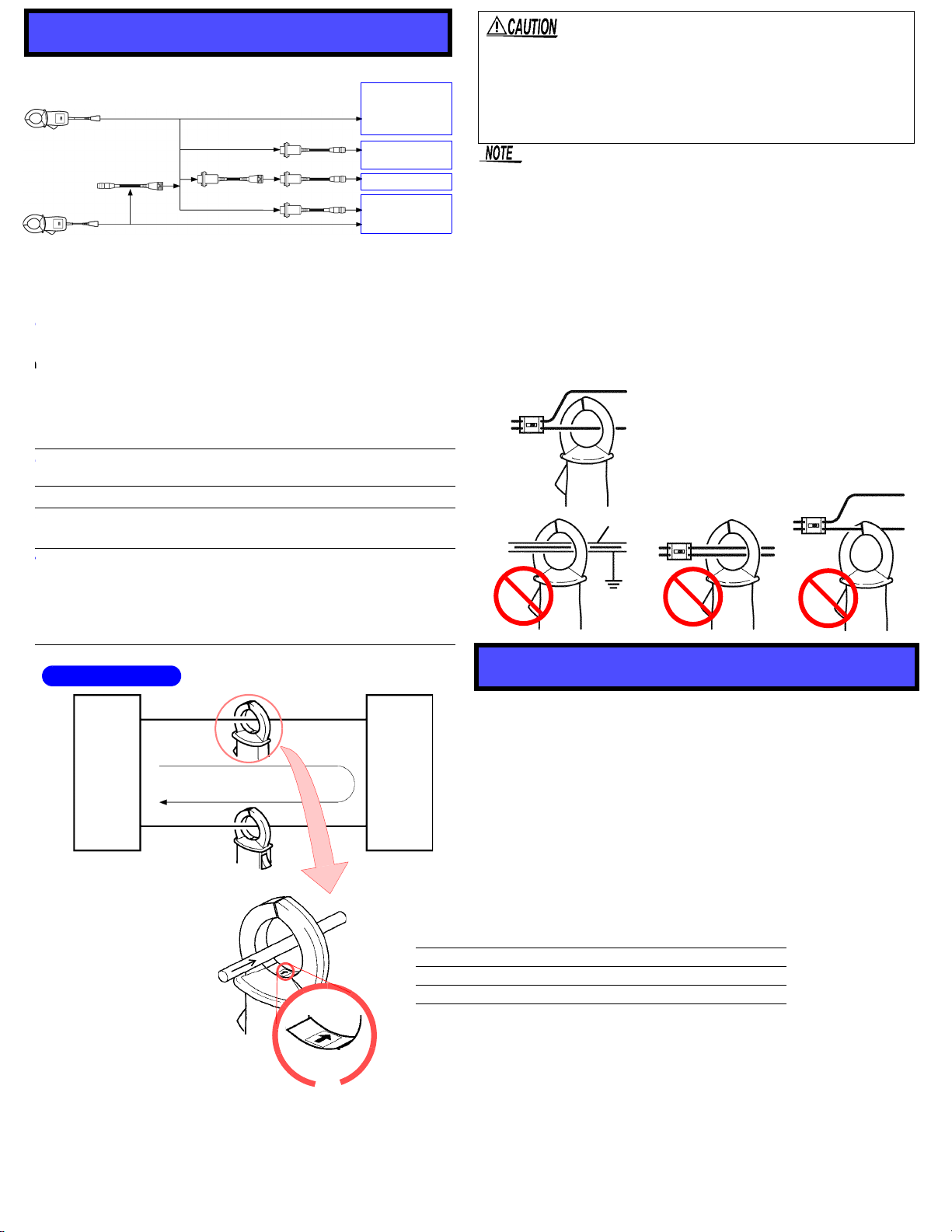
9705 Conversion Cable*1, 9318 Conversion Cable*1,
CT9900 Conversion Cable*1, CT9901 Conversion Cable*2
The Conversion Cable makes it possible to connect to and use
with products that cannot be directly connected to the 9272-05
or 9272-10. (Refer to “Connection example”) (No figures are
added to the accuracy.)
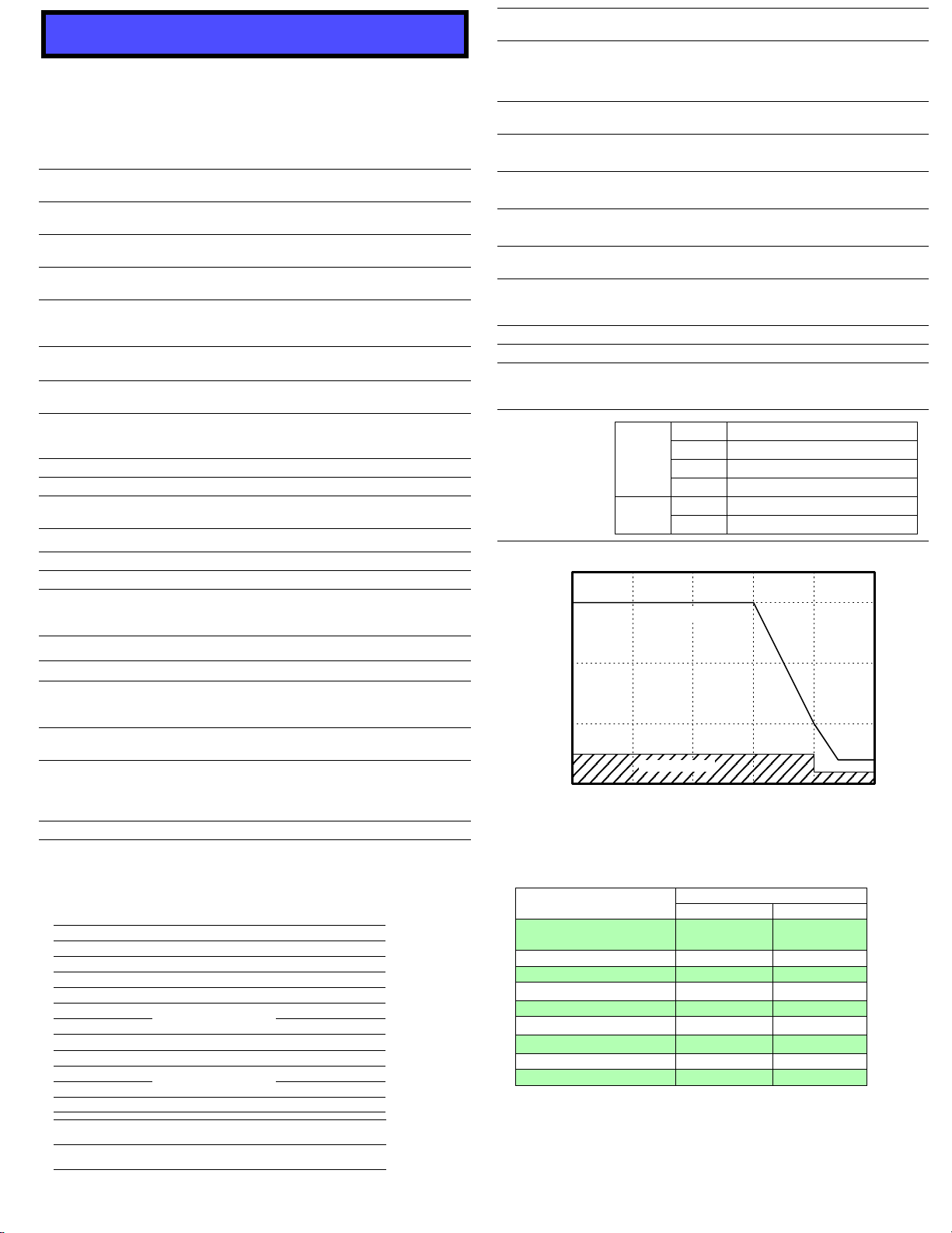
CT9902 Extension Cable
*2
(5 m), CT9903 Extension Cable
*1
(5 m)
• Single sensor cable, 5 m extension (max. 10 m extension)
• Up to two extension cable is connectable. (If three or more-
extension cables are connected to the device, its perfor-
mance is not guaranteed)
• Add the following values to each of the accuracy per cable:
Amplitude accuracy: ±0.1% rdg. (DC f*3 1 kHz)
±0.5% rdg. (1 kHz < f*3)
Phase accuracy: ±(0.1 × f*3 kHz)° (1 kHz <f*3)
*1: For 9272-10, *2: For 9272-05, *3: frequency
Inspection and Maintenance
Pack the device so that it will not sustain damage during ship-
ping, and include a description of existing damage. We cannot
accept responsibility for damage incurred during shipping.
Safety
9272-05
9272-10
CLAMP ON SENSOR
Instruction Manual
Feb. 2017 Revised edition 5
Printed in Japan
9272C981-05 17-02H
EN
• This device is designed
61010 Safety Standards, and has been
oughly tested for safety prior to shipment.
However, mishandling during use coul
in injury or death, as well as damage
device. Be certain that you underst
instructions and precautions in th
before use. We disclaim any responsibility
accidents or injuries not resulting directly
device defects.
• To avoid short circuits and potentially
threatening hazards, never attach the
to a circuit that operates at more than 600V
Indicates cautions and hazards. When the symbol is
printed on the product refer to a corresponding to
Instruction Manual.
Indicates that the device may be connected to
nected from a live circuit.
Indicates a double-insulated device.
Indicates AC (Alternating Current).
Indicates that incorrect operation presents an
hazard that could result in serious injury or
user.
Indicates that incorrect operation presents a
hazard that could result in serious injury or
user.
Indicates that incorrect operation presents a
of injury to the user or damage to the device.
Indicates advisory items related to pe
rect operation of the device.
Indicates a prohibited action.
Avoid the following locations that could cause an accident or dam-
age to the device.
Exposed to direct
sunlight
Exposed to high temper-
ature
In the presence of
corrosive or explosive
gases
Exposed to liquids
Exposed to high humid-
ity or condensation
Exposed to strong
electromagnetic fields
Near electromagnetic
radiators
Exposed to high levels
of particulate dust Subject to vibration
• Clamp sensor should only be connected to the sec-
ondary side of a breaker, so the breaker can prevent
an accident if a short circuit occurs. Connections
should never be made to the primary side of a breaker,
because unrestricted current flow could cause a seri-
ous accident if a short circuit occurs.
• To avoid electric shock, short circuits and damage to
the device, observe the following precautions:
Check the position of the range switch before taking
measurements.
Disconnect the conductor from the measurement
object before switching ranges.
• To avoid electric shock, do not touch the portion
beyond the protective barrier during use.
• Do not allow the device to get wet, and do not take
measurements with wet hands. This may cause an
electric shock.
• To avoid electric shock when measuring live lines,
wear appropriate protective gear, such as insulated
rubber gloves, boots and a safety helmet.
• Before using the device, make sure that the insulation
on the probes is undamaged and that no bare conduc-
tors are improperly exposed. Using the device in such
conditions could cause an electric shock, so contact
your dealer or Hioki representative for repair.
• Note that the device may be damaged if current exceeding the
selected measurement range is applied for a long time.
•When the digital power meter or the clamp unit’s power is turned
off, do not apply current to the clamp sensor. Doing so may
damage the device.
•When disconnecting the connector, be sure to release the lock before
pulling off the connector. Forcibly pulling the con-nector without
releasing the lock, or pulling on the cable, can damage the connector.
•
•
To prevent damage to the connected instruments and the sensor,
never connect or disconnect a sensor while the pow-er is on, or while the
sensor is clamped around a conductor. Toavoid damage tothe device,
protect it from physicalshock when transporting and handling. Be
especially careful to avoid physical shock from dropping.
• Do not store or use the device where it could be exposed to di-rect sunlight,
high temperature or humidity, or condensation. Under such conditions, the
device may be damaged and insu-lation may deteriorate so that it no longer
meets specifications.
• Measurements are degraded by dirt on the mating surfaces
of the jaws so keep the surfaces clean by gently wiping with
a soft cloth.
• To avoid breaking the cables, do not bend or pull them.
• Avoid stepping on or pinching cables, which could damage
the cable insulation.
• Keep the cables well away from heat sources, as bare con-
ductors could be exposed if the insulation melts.
• Correct measurement may be impossible in the presence of
strong magnetic fields, such as near transformers and high-
current conductors, or in the presence of strong electromag-
netic fields such as near radio transmitters.
• This device may cause interference if used in residential areas.
Such use must be avoided unless the user takes special mea-
sures to reduce electromagnetic emissions to prevent interfer-
ence to the reception of radio and television broadcasts.
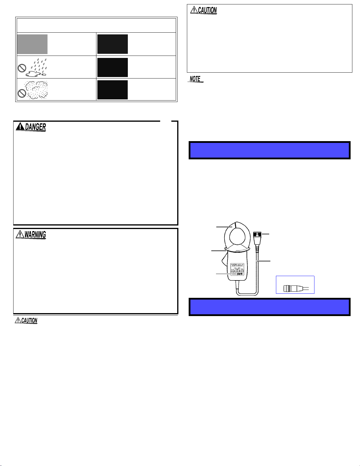
Overview
Options
Jaws
Cable
Range switch
Barrier
Output connector
9272-05
Output connector
www.GlobalTestSupply.com
Find Quality Products Online at: sales@GlobalTestSupply.com