- page 2 -
ITIC (CBEMA) curve
The ITIC curve judges the allowable level of
voltage RMS fluctuation from the voltage swell,
voltage dip and interruption events.
The analysis is made by the period and depth of
each event according to the limit value of the ITIC
curve.
The ITIC (Information Technology Industry
Council) curve is the most recent version of the
older CBEMA (Computer and Business
Equipment Manufacturers Association) curve.
Both were created by CBEMA. The original
CBEMA curve was widely used in the U.S.A.
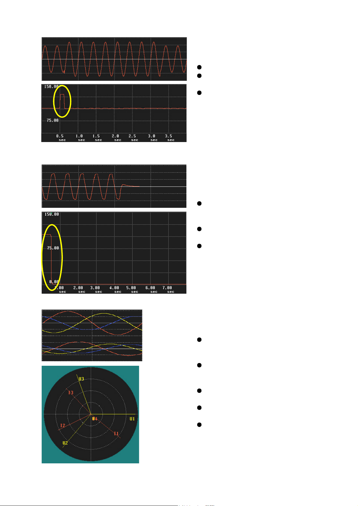
Main Power Quality Parameters
1. Transient overvoltage (impulse)
1) Phenomenon
Radical changes in voltage with high voltage
peaks
2) Cause
3) Damage
4) Analysis
Lightning strikes
Power circuit switching
Closure of inductive circuits
Arc to the ground
Load switching
Contact of a bouncing relay
Destruction of power supplies of
equipment
Equipment reset
Waveform (Maximum voltage level, Rise
time, Phase angle, Fluctuation,
Repeatability)
The faster rise time means a closer
occurring point.
2. Voltage Dip
1) Phenomenon
Instantaneous drop of RMS voltage
2) Cause
3) Damage
Large inrush current by turning on heavy
loads
Accident in the distribution network
(Lightning, snow, ice, contact of birds/
trees, effects of accidents)
Short-circuit
Stop or equipment reset