HiWeigh PHA User manual

A professional weighing products manufacturer and supplier
An ISO9001 registered company
@No.335 Haishen, Xingxin Road, Huinan Town, Pudong District, Shanghai 201301, China
www.hiweigh.com All rights reserved, specifications subject to change without notice
Value Each Gram
R
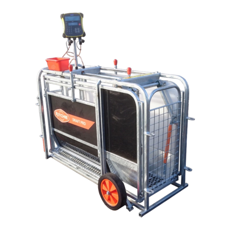
PHA | PHAS
Pallet Scale
User Manual
v.201802

Value Each Gram

Thank you for using this hand pallet truck with scale. For your safety and correct operation of the scale, please read these
instructions carefully before using it.
NOTE:
1. All of the information reported herein is based on data available at the moment of printing. The factory
reserves the right to modify its own products at any moment without notice and incurring any sanction. So it is
suggested to always verify possible updates.
(2) Prior to use this hand pallet truck with scale, the battery of scale must be charged enough.
1. GENERAL SPECIFICATIONS
Model
Capacity
Graduation
Weighing
Accuracy
Fork size
Length
Width over forks
Fork Width
PHA
2000 kg
0.5 kg
± 0.05%
1150mm
540mm
160mm
PHA680
2000 kg
0.5kg
± 0.05%
1220mm
680mm
160mm
PHAS
2000kg
0.5 kg
± 0.05%
1150mm
540mm
160mm
PHAS680
2000kg
0.5kg
± 0.05%
1220mm
680mm
160mm
* Capacity of 3000kg available
* Materials and specifications are subject to change without notice.
2. AT TAC H H ANDL E TO PU MP U NIT
2.1Remove the handle component (H100), insert it into the pump shell (B101).
2.2Remove the axle from plastic bag(B09)
2.3Insert the axle (B09) at one end of the pump shell(B101), then pump shell (B101) and handle components (H100)
connection. Please note axle (B09) the position of the hole, Let the steel wire and nut on the chain (H09) through the axle
(B09) hole (See the hydraulic system diagram and the handle component diagram).
2.4Spring pin (B10) fixed the axle(B09).
2.5Handle (H01) press the pump plunger(B18), and remove the pin(B11).
2.6Raise the crank link (B46) and put the pin on rod and chain (H09) into the groove of crank link (B46).

2
3. TO ADJUST RELEASE DEVICE
On the handle of the pallet truck, you will find the control lever (H01) which can be set in three positions (See Fig. 1):
LOWER=to lower the forks; NEUTRAL=to move the load; ASCENT=to raise the forks. After assembling the handle, you can
adjust the three positions.
3.1 First tighten the setting screw (B46) on the crank link (B48) until the LOWER position function works.
3.2 If the forks elevate while pumping in the NEUTRAL position, turn the setting screw (B48) clockwise until pumping the
handle does not raise the forks andthe NEUTRAL position functions correctly.
3.3 If the forks descend while pumping in the NEUTRAL position, turn the setting screw (B48) counter-clockwise until the
forks do not lower.
3.4 If the forks do not descend when the control lever (H01) is in the LOWER position, turn the setting screw (B48)
clockwise until raising the control lever (H01) lowers the forks. Then check the NEUTRAL position as per item 4.2 and
4.3.
3.5 If the forks do not lift while pumping in the ASCENT position, turn the setting screw (B48) counter-clockwise until the
forks elevate while pumping in the ASCENT position. Then check the NEUTRAL and LOWER position as per item 4.2,
4.3 and 4.4.
4. MAINTENANCE
4.1 OIL
Please check the oil level every six months. Total oil amount is about 260 ml, add injection oil 50-100 ml, this must be
with the forks in the lowered position.
Add or change the hydraulic oil according to the table below.
Temperature
Oil
-20~+40
L-HV46 Hydraulic oil
4.2 HOW TO EXPEL AIR FROM THE PUMP UNIT
Air may enter the unit when the seals are replaced. Lift the control lever (H01) to the LOWER position, then move the
handle up and down for several times.
4.3 DAILY CHECK AND MAINTENANCE
Daily check of the pallet truck can limit wear and tear of the unit. Pay special attention to the wheels, the axles, the
handle, the forks and lift and lower control.
4.4 LUBRICATION
Use motor oil or grease to lubricate all moveable parts.

3
5. GUIDE TO SAFE OPERATION
For safe operation of the truck, please read all warning signs and instructions here and on the truck before using this truck.
5.1 Do not operate the pallet truck unless you are familiar with it and have been trained or authorised to do so.
5.2 Do not operate the truck unless you have checked its condition. Give special attention to the wheels, the handle
assembly, the forks, lift and the lower control.
5.3 Do not use the truck on sloping ground.
5.4 Never place any part of your body in the lifting mechanism or under the forks or load. Do not carry passengers.
5.5 The operator should wear gloves and safety shoes for protection.
5.6 Do not handle unstable or loosely stacked loads.
5.7 Do not overload the truck.
5.8 Do not subject to unbalanced load, either side to side or along the length of the frame (refer to Fig. 2/B).
5.9 The capacity of the truck assumes an evenly distributed load with the centre of the load being at the halfway point
of the length of the forks (refer to Fig. 2)
5.10 Make sure that length of the forks matches the length of the pallet.
5.11 Lower the forks to lowest height when the truck is not being used.
5.12 At other specific conditions or places, the operator should operate the pallet truck carefully.
6. TROUBLE SHOOTING
NO
TROUBLE
CAUSE
ACTION
1
The forks do not lift
to maximum height.
-Not enough hydraulic oil.
-Add more oil.
2
The forks do not lift
up.
-Not enough hydraulic oil.
-The oil has impurities.
-Discharge valve is out of
adjustment.
-Air in the hydraulic oil.
-Pour in more filtered oil.
-Change the oil.
-Adjust the setting screw (B48).
-Expel the air.
3
The forks do not
descend.
-The rod (B101) and the pump
cover (B02) are deformed resulting
from a seriously unbalanced load.
-A part has been broken or been
deformed resulting from
unbalanced load.
-The setting screw (B48) is not in the
correct position.
-Replace the rod (B02) or pump
cover (B101).
-Repair or replace component.
-Adjust the setting screw (B48).
4
Leaks
-Seals worn out or damaged.
-Some parts may be cracked or
worn out.
-Replace seals with new ones.
-Check and replace with new ones.
5
The forks descend
without being
lowered.
-Impurities in the oil cause the
discharge valve (B106) to fail to
close.
-Air in the oil.
-Seals worn or damaged.
-Discharge valve (B106) is out of
adjustment.
-Replace with filtered oil.
-Expel the air.
-Replace with new ones.
-Adjust the setting screw (B48).

4
7. WEIGHING OPERATION (Detailed Info Please Refer to Chapter 11 and later).
7.1 Put the control lever in the LOWER position and lower the truck to lowest position.
7.2 Press the ON key to turn the system on. After the start-up sequence the indicator will display the weight.
7.3 Weighing method for gross weight:
Press the ZERO key to set the gross weight to 0. Put the forks under the pallet and check that the load is properly
balanced. Put the control lever in the ASCENT position, pump the handle to make the forks rise until the pallet has
left the ground. When the indicator is stable, the gross weight of the goods (total weight of the pallet and the goods)
is shown.
7.4 Weighing method for net weight:
To d is p l a y t h e w e i g h t o f t h e goods without the weight of the pallet (or another container):
7.4.1 Weigh single standard pallet, for example: weight of pallet: 40kg.
7.4.2 Press the TARE key, the indicator will display “0kg”.
7.4.3 Remove the pallet from the forks, the indicator will display “-40kg”.
7.4.4 Weigh the goods on the pallet as shown in 7.3, when the indicator is stable, the net weight of the goods is shown.
7.5 Switch between kg and lb.
Keep pressing FN key to switch the kg/lb unit (for LED version: keep pressing * key to exchange the kg/lb unit).
7.6 Turn off the I ndicator
Press on the OFF key to turn off the indicator
8. BATTERY POWER DATA AND REPLACEMENT
8.1 How to change batteries:
8.1.1 Loosen the screws of the indicator case and open it.
8.1.2 open the screw on battery and pull out battery, out the socket.
8.1.3 put the new battery and insert the socket.
8.1.4 Screw the bolts and fix it well again
Figure 1

5
9. WIRING DIAGRAM OF JUNCTION BOX
10. CHANGING THE PAPER (optional with Printer)
10.1 Pull the lever to open the cover of the printer. Place the paper roll. Make sure the flap is at the top of the printer,
facing towards you. Hold on to the paper when closing the printer. Push the cover closed firmly.
L1L4 Connect sensor connector
GND
silver
S
white
S
green
E
black
E
red
L0 Connect meter connector
GND
silver
S
white
S
green
E
black
E
red

1
11. Keypad
K7 series indicator with7 function keys:
BUTTON FUNCTIONS SHORT ON THE MANUAL
Power Off [ON]
Power On [OFF]
ESC
Print [PRINT]
Long press to display time/date
User function set [FN]
Long press to exchange weight unit
Enter function during parameters configuration
Accumulate [ACCU]
Long press to retrieve weight records
Move digits to right during parameters configuration
Tare [TARE]
Long press to display percentage function
Increase the digits during configuration
Zero [ZERO]
Decrease the digits during parameters configuration
12. Operations
12.1 Switch On/Off
Push [ON] key to turn on the indicator
Push [OFF] key to turn off the indicator
12.2 Zero

2
If the indicator not on zero point and the weight value <2%F.S., push
[ZERO]
key to zero the scale,
and the zero arrow will display
12.3 Tare
Manual Tare: Put the container on the scale (weight>0) and after the read stable (also the tare
arrow not appear), push [TARE] the scale will remove the weight read and record as
tare, and the scale will display the net weight, push [TARE] again, it will display the
gross weight (tare + net weight)
Repeat Tare: After the first tare operation, put the 2nd weight on the scale, push [TARE], it will
display the gross weight of 1st+2nd weight and push [TARE] again, it will take that
gross weight as new tare weight and start the new net weighing operation.
Remove Tare: When the net weight display and the tare arrow appears, push [TARE], it will remove
the tare value and display the gross weight, and the tare arrow disappears.
Auto Tare: When the user function (AUT) set to be 10 or 11 and the weight reach to the valve
value as it set, the scale will do tare automatically, refer to AUT configuration.
12.4 Print
On manual print/accumulate mode, when the weight value >20d and stable, push [PRINT], it will
print the weight bill, and it can be printed once again if you push [PRINT] again.
12.5 Accumulate and Print
On manual print/accumulate mode, when the weight value >20d and stable, push [ACCU], it will
print the weight receipt and accumulate to the record (also it will display the accumulation times
like [n 12]), next print/accumulating available only after the weight value <20d.
12.6 Weight Unit Exchange
Long press [FN] key for 2 seconds to exchange between the 1st unit and 2nd unit.
Kg and lb, g and oz, t only.
13. Accumulated Record Retrieve and Clean
(on weighing mode)
Operation
Display
Explanation
Long Push [ACCU]
[n 12]
Display accumulated times
Push [
]
[ H 3 ]
Display the first 4 digits
Push [
]
[ L506.5]
Display the following 4 digits, accumulated weight=3506.5
Push [
↓
]
[ n 12]
When it displays the accumulated times, push
[
↓
]
to clean
the accumulated record
Push [FN]
[ 0 ]
Return to weighing mode
14. User Setting Menu
Push [FN]
[Aut 00]
Weighing mode set
Push [FN]
[000200]
Auto tare valve value (when Aut=10 or 11)

3
Push [FN]
[ PrInt ]
Communication, Printing Format and Percentage Set
Push [FN]
[ PErC ]
Set weight value for percentage weighing (100%)
Push [FN]
[ SEtP ]
Set setpoints
Push [FN]
[ PCS ]
Set samples quantity (Aut=07)
Push [FN]
[ 0.002]
10 times resolution
Push [FN]
[ 0.00]
Return to weighing mode
15. Weighing Mode Set
Operation
Display
Explanation
Push [FN]
[Aut 00]
User functions set
Push [
→
] and [
]
or [
↓
]
Push [FN]
[Aut 01]
00: Normal weighing mode, manual print/accumulate
01: Normal weighing mode, automatic print/accumulate
after the weight stable, auto arrow appears
02: Normal weighing mode, automatic save the weight value,
and print/accumulate it after the load < 20d and auto
arrow appears
03: Dynamic weighing mode, automatic print/accumulate
after the weight <20d, auto arrow appears
04: Peak hold mode, automatic print/accumulate after the
weight <20d, auto arrow appears
05: Dynamic weighing mode, manual print/accumulate
06: Peak hold mode, manual print/accumulate
07: Counting mode, manual print/accumulate
08: Positive/Negative weighing, use for testing the tension or
compression force
09: Minus weighing mode
10: Automatic tare mode
11: Continuous automatic tare mode
Modify the mode and push [FN] to confirm
Push [FN]
Push [
] or [
↓
] to
modify
[Aut 03]
[t 3 ]
If the Aut=03 or 05, there is the time set for dynamic
weighing (average weight during the set time)
After set done, push [FN] to confirm.
Push [FN]
[ 0 ]
Return to weighing mode
16. Communication | Print Configuration
Operation
Display
Explanation
Push [FN]
[Aut 00 ]
Weighing mode selection
Push [FN]
[ PrInt ]
Communication, Printing Set
Push [
→
] and [
]
or [
↓
]
Push [FN]
[ Adr 00]
Communication address selection

4
Push [
→
] and [
]
or [
↓
]
Push [FN]
[ b1 24]
COM1 baud rate select:
24=2400 48=4800 96=9600 144=14400 192=19200
Push [
→
] and [
]
or [
↓
]
Push [FN]
[CHE1 n]
COM1 Check mode
n: None
E: Even check
O: Odd check
S: Always 0
A: Always 1
Push [
→
] and [
]
or [
↓
]
Push [FN]
[C1 Ct1]
COM1 Output
Ct1: Continuous output
Cnd: Command (Modbus)
F1: Print format 1
F2: Print format 2
F3: Print format 3
Ct2: Stable output
Ct3: Continuous output (format = Ct2)
Push [
→
] and [
]
or [
↓
]
Push [FN]
[ b2 24]
COM2 baud rate select:
24=2400 48=4800 96=9600 144=14400 192=19200
Push [
→
] and [
]
or [
↓
]
Push [FN]
[CHE2 n]
COM2 Check mode
n: None
E: Even check
O: Odd check
S: Always 0
A: Always 1
Push [
→
] and [
]
or [
↓
]
Push [FN]
[C2 Ct1]
COM1 Output
Ct1: Continuous output
Cnd: Command (Modbus)
F1: Print format 1
F2: Print format 2
F3: Print format 3
Ct2: Stable output
Ct3: Continuous output (format = Ct2)
Push [
→
] and [
]
or [
↓
]
Push [FN]
[ dF 2]
Date format
0 = d/m/y
1 = m/d/y
2 = y/m/d
Push [
→
] and [
]
or [
↓
]
Push [FN]
[tIt 2]
Printing head
0: None
1: On top
2: On bottom
3: Both (top and bottom)
Push [
] or [
↓
]
and [
→
]
[00¯077]
[01¯079]
….
Top head input (total 64 letters):
00: The sequence of letter

5
Push [PRINT] or
[ON] to next letter
Push [FN] to end
[25¯255]
087: ASCII code, 087 represents M, 079 represents O… (refer
to appendix I) and input 255 to end the head
Push [
] or [
↓
]
and [
→
]
Push [PRINT] or
[ON] to next letter
Push [FN] to end
[00¯077]
[01¯079]
….
[25¯255]
Bottom head input (total 64 letters):
00: The sequence of letter
087: ASCII code, 087 represents M, 079 represents O… (refer
to appendix I) and input 255 to end the head
[ 0.0]
Configuration saved and back to weighing mode
17. Percentage Weighing
Operation
Display
Explanation
Push [FN]
[Aut 00 ]
Weighing mode selection
Push [FN]
[ PrInt ]
Communication, Printing Format and Percentage Set
Push [FN]
[ PErC ]
Set weight value for percentage weighing (100%)
Push [
→
] and [
]
or [
↓
]
Push [FN]
[ 3000]
Input the weight value for 100% index
[ 0.0]
Back to the weighing mode
Note: Percentage weighing available only when Aut=00, and long press [TARE] for 2 seconds to start the
percentage weighing mode.
18. Setpoints
Operation
Display
Explanation
Push [FN]
[Aut 00 ]
Weighing mode selection
Push [FN]
[ PrInt ]
Communication, Printing Format and Percentage Set
Push [FN]
[ PErC ]
Set weight value for percentage weighing (100%)
Push [FN]
[ SEtP ]
Set setpoints
Push [
→
] and [
]
or [
↓
]
Push [FN]
[oP 0]
Setpoints mode:
oP=0: no output
oP=1: 2 setpoints output
oP=2: 4 setpoints output (for 3-LED alarming lights)
oP=3: 4 setpoints output
Push [
→
] and [
]
or [
↓
]
Push [FN]
[ALA 0]
Beeper working mode:
ALA=0: No beep
ALA=1: It beeps when the weight out of range (Hi/Lo, stable)
ALA=2: It beeps when the weight within range (OK, stable)
Push [
→
]
Push [
] or [
↓
]
Push [FN]
[A00500]
[000000]
[000200]
A setpoint input
Push [
→
]
[b00700]
B setpoint input

6
Push [
] or [
↓
]
Push [FN]
[000000]
[000300]
Push [
→
]
Push [
] or [
↓
]
Push [FN]
[C01000]
[000000]
[000400]
C setpoint input
Push [
→
]
Push [
] or [
↓
]
Push [FN]
[D01200]
[000000]
[000500]
D setpoint input
[ 0.0]
Back to the weighing mode
19. Counting
19.1 Sampling
Put the samples on the scale (if the scale is not zero, please zero or tare the scale firstly) and it’s more
precise if there are more samples counted (1-999)
Operation
Display
Explanation
Put the samples on
the scale
[ 26.0]
Display the weight of the samples
Push [FN]
Push [
→
]
Push [
] or [
↓
]
[Aut 00 ]
[Aut 07 ]
Select Aut=07 (counting mode)
Push [FN]
[ PrInt ]
Communication and Printing Set
Push [FN]
[ PErC ]
Set weight value for percentage weighing (100%)
Push [FN]
[ SEtP ]
Set setpoints
Push [FN]
[ PCS ]
Set the number of samples, this menu appears when Aut=07
Push [
→
]
Push [
] or [
↓
]
[Cnt000]
[Cnt030]
Input the samples number
Example = 30
Push [FN]
[C 30]
Save the samples number
Ready for counting operation
19.2 Counting
After sampling saved, put the goods on the scale, it will display the quantity of the goods, like [C 108], push
[ON] key to shift the display between the quantity or the weight of the goods, and after the weight stable,
push [PRINT] or [ACCU] to print the receipt or accumulated receipt.
19.3 Counting Records and Clean
After sampling saved, put the goods on the scale, it will display the quantity of the goods, like [C 108], push
[ON] key to shift the display between the quantity or the weight of the goods, and after the weight stable,
push [PRINT] or [ACCU] to print the receipt or accumulated receipt.
Operation
Display
Explanation
[ C 108]
On counting mode

7
Long press [ACCU]
[ n 8]
Display the accumulated times
Push [
]
[ C 532]
Display the total quantity
Push [FN]
[ C 108]
Back to counting mode
Push [
↓
]
[ n 8]
When it displays the accumulated times, push
[
↓
]
to clean
the accumulated value and back to counting mode
20. Positive/Negative Weighing
(Aut=08)
On this mode, the indicator can accept the positive or negative signal, when it displays the positive
weight, tare operation is available, when it displays the negative weight, the tare operation can’t
access. Accumulating and printing is unavailable for this mode.
21. Minus Weighing
(Aut=09)
On this mode, the indicator will display the removed load.
Put the object on the scale, long press [ZERO] to zero the scale, now remove the object and the
scale will display the removed weight. Tare/Accumulate/Print is available for this mode.
22. Automatic Tare
After Aut=10 or 11 configured, press [FN], it will display the valve value [000200], set the value by
[→] [↑] or [ ↓ ], if the decimal point set as 0.0, the [000200]=20.0
(Aut=10) Auto Tare
On this mode, when the weight > the valve value, it will do tare automatically.
When the scale back to zero (empty), it will clean the tare automatically.
(Aut=11) Continuous Auto Tare
On this mode, when the weight > the valve value, it will do tare automatically, and now put more
objects on the scale, and after the weight stable, press [PRINT] or [ACCU] to print or accumulated
print, the scale will do tare again by itself.
When the scale back to zero (empty), it will clean the tare automatically.
23. Clock Adjust
When it display time or date, press [↑] to shift display of time or date.
Operation
Display
Explanation
[ 27 ]
On weighing mode
Long Press [PRINT]
Push [
→
] and [
]
or [
↓
] to change
[00:00:80]
[09:30:01]
Display time (hour/minute/second)
After modifying, push [FN] to confirm
Push [
]
Push [
→
] and [
]
or [
↓
] to change
[00.01.01]
Push to
[
]
display the date
After modifying, push [FN] to confirm
Push [FN]
[ 0.0]
Back to the weighing mode

8
24. Weight Record Retrieve and Print
Operation
Display
Explanation
[ 27 ]
On weighing mode
Long Press [ACCU]
[n 8 ]
Display the accumulated times
Push [
→
]
Push [
] or [
↓
] to
change
[000008]
Input the serial number of the weight record
Push [FN]
[r 2]
Display the sequence number of that record
Push [PRINT]
[r 3]
Display the next record
Push [ON]
[r 2]
Display the previous record
Push [
]
[16.06.03]
Display the date of that record
Push [
]
[14:53:02]
Display the time of that record
Push [
]
[ 30.06]
Display the gross weight of that record
Push [
]
[ 20.00]
Display the tare weight of that record
Push [
]
[ 10.06]
Display the net weight of that record
Push [
]
[ 153]
Display the quantity of that record (for counting)
Push [FN]
[ 27.00]
Push [FN] to return to weighing mode during any data display
(date-time-gross weight-tare weight-net weight-quantity)
Push [PRINT]
[16.06.03]
Push [PRINT] to print the record during any data display
Push [
→
] and [
]
or [
↓]
[b 0001]
Push
[
→
]
to input the start number of the records (for
retrieve)
Push [FN]
Push [
→
] and [
]
or [
↓]
[E 0008]
Input the end number of the records (for retrieve)
Push [FN]
[ 27.00]
It will print all records from 0001 to 0008 and back to
weighing mode after the printing ends.
25. Communication Protocol
Byte format: 8 bits; if there is check bit, it’s the first digit; one stop bit
Output format:
1. Continuous format (Ct1, Ct2, Ct3): if the display weight = -123.45
Ct1: no matter the weight stable or not, output continuously:
Adr=00-98: =54.3210-=54.3210-=54.3210-…
Adr=99: =-0123.45=-0123.45=-0123.45…
Ct2: When the weight stable, output the following ASCII code:
A B CCCCCC D EE F G
02, 2D, 30, 31, 32, 33, 2E, 34, 35, 20, 6B, 67, 47, 0D

9
A
B
C
D
E
F
G
Start
0x02
Sign
>=0, 0x20 (space)
<0, 0x2D (-)
Weight
include decimal point
Space
0x20
Unit
kg/lb/t
G/N
Enter
0x0D
Ct3: No matter the weight stable or not, continuous output the Ct2 data.
2. Command (Cnd)
COM1: Modbus
COM2: Handshaking, the computer send the request (ASCII) as below:
P – print gross/tare/net weight
G – Print gross weight
B – Print tare weight
N – print net weight
A – Print quantity
Z – Zero
T- Tare
C – Clean tare
3. Print format (F1)
Weighing Bill
Counting Bill (Aut=07)
MOORANGE ELECTRONICS
03-06-2017
14:58:26
No.0002
G: 7.73kg
T: 4.82kg
N: 2.91kg
www.moorange.com
MOORANGE ELECTRONICS
03-06-2017
14:58:26
No.0002
G: 7.73kg
T: 4.82kg
C: 54pcs
www.moorange.com
4. Print format (F2)
Weighing Bill
Counting Bill (Aut=07)
No.0002 03-06-2017 14:58:26 7.73kg
No.0002 03-06-2017 14:58:26 7.73kg 54pcs
5. Print format (F3)
Weighing Bill
0002 03-06-2017 14:58:26 7.73kg 4.82kg 2.91kg
Counting Bill (Aut=07)
0002 03-06-2017 14:58:26 7.73kg 4.82kg 2.91kg 54pcs
6. Accumulated Format
Weighing Bill
Counting Bill (Aut=07)
03-06-2017
03-06-2017

10
14:58:26
No.0002
S: 25.02kg
14:58:26
No.0002
C: 108pcs
S: 25.02kg
26. Setpoints Output
A B C D 4 setpoints, A<B<C<D
Relay board optional, not included in standard package
26.1 oP=1 (2 relay output 1# and 2#)
W<A or W>D: Hi/Ok/Lo LED lights off and no relay output
AWB: Lo LED on, 1# relay output
B<W<C: OK LED on, no relay output
CWD: Hi LED on, 2# relay output
Relay connecting (sharing with RS232C DB9 interface):
Pin6 & pin7: 1# relay NO (normally open)
Pin8 & pin9: 2# relay NO (normally open)
26.2 oP=2 (4 relay output 1#, 2#, 3# and 4#)
If connecting to the 3-LED alarming lights:
1# - yellow, 2# - green, 3# - red, 4# - beeper
W<A: Lo LED lights on, 1# and 4# relay output
AWB: Lo LED on, 1# relay output
BWC: OK LED on, 2# relay output
CWD: Hi LED on, 3# relay output
W>D: Hi LED on, 3# and 4# relay output
Relay connecting (sharing with RS232C DB9 interface):
Pin1: COM
Pin6: 1# relay NO (normally open)
Pin7: 2# relay NO (normally open)
Pin8: 3# relay NO (normally open)
Pin9: 4# relay NO (normally open)
26.3 oP=3 (4 relay output 1#, 2#, 3# and 4#)
WA: Lo LED lights on, 1# and 2# relay output
WB: Lo LED on, 2# relay output
BWC: OK LED on
W≥C: Hi LED on, 3# relay output
W≥D: Hi LED on, 3# and 4# relay output
Relay connecting (sharing with RS232C DB9 interface):
Pin1: COM
Pin6: 1# relay NO (normally open)
Pin7: 2# relay NO (normally open)
Pin8: 3# relay NO (normally open)

11
Pin9: 4# relay NO (normally open)
27. Trouble Shooting
ERR0R
28. Precaution
• Indicator should be far away from heat resource while using, avoid direct sunlight
• Do not place the indicator in the dusty surroundings or the site vibrant
• Keep out of chemical erosion, operating temperature range will be -10...40ºC, relative humidity is no
less than 85%, without any corrupt gas in air.
• Never pour the water into the indicator to avoid the damage to the electronic components.
• Housing, head pallet, wire connector should be sealed entirely. Users do not open sealed device or
connect with wire without any expert advice. In case any malfunction of indicator occurs, please send
the indicator for maintenance.

12
• The indicator will charge the internal battery at all times when it is connected to the main power.
• When the battery <20%, the battery icon will be empty like [ ] which indicates the recharge on
time, when the battery almost empty, the display will twinkle to indicate the immediate charge.
• When the battery used up, the indicator will power off automatically to protect the over-discharge of
the battery
• When the indicator set with auto power off, the backlight will off after 30 seconds no operation
• When the indicator set with auto power off, it will turn off automatically after 30 minutes no
operation
• When a problem occurs to the indicator, please switch off it immediately and send back to our
authorized dealers or our company, for repair
• The warranty period is one year since the delivery date, covering all manufacturing faults. All man-
made problems, battery and freight abroad not covered.
• Life-time technical support

This manual suits for next models
3
Table of contents
Other HiWeigh Scale manuals

HiWeigh
HiWeigh HH User manual
HiWeigh
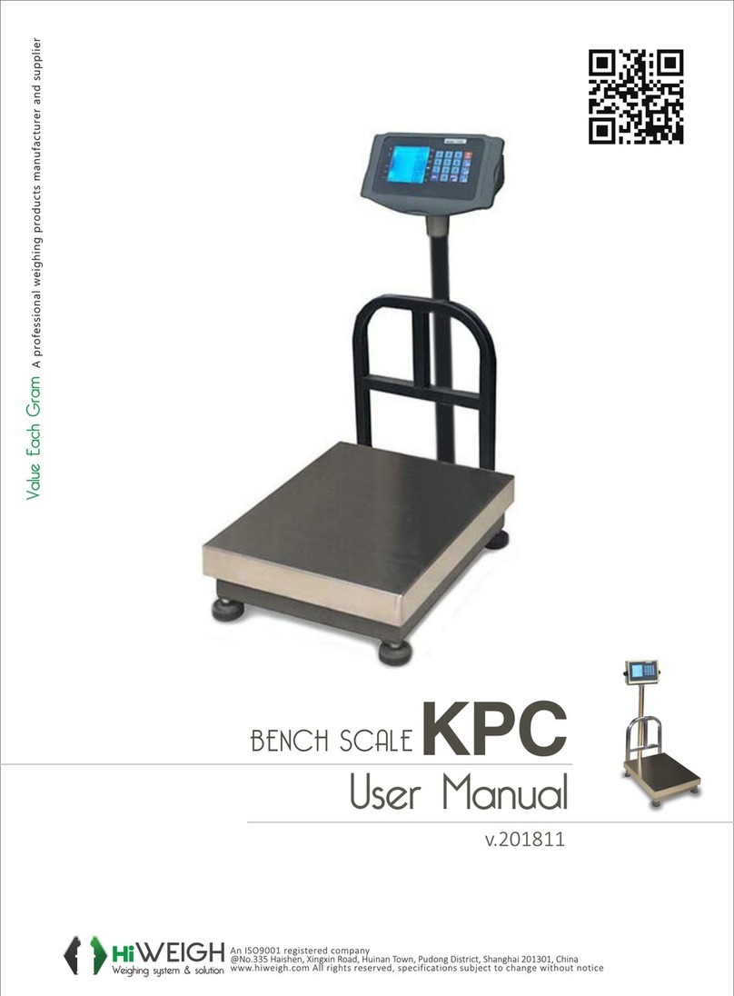
HiWeigh KPC User manual

HiWeigh
HiWeigh NSS User manual
HiWeigh
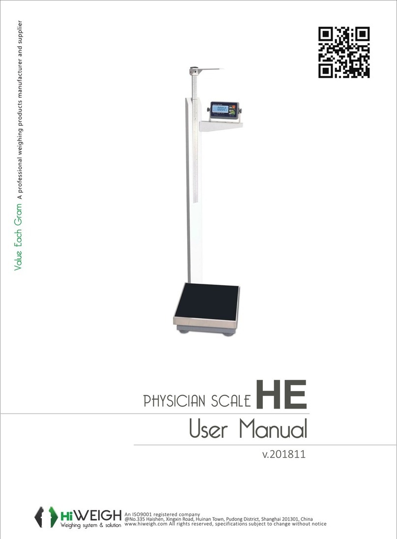
HiWeigh HE User manual

HiWeigh
HiWeigh PC5 User manual

HiWeigh
HiWeigh BJA Series User manual

HiWeigh
HiWeigh P3 User manual
HiWeigh
HiWeigh CSX Series User manual
HiWeigh
HiWeigh BAM User manual
HiWeigh
HiWeigh PCP User manual


