manuals.online logo
Brands
  1. Home
  2. •
  3. Brands
  4. •
  5. HK Instruments
  6. •
  7. Transmitter
  8. •
  9. HK Instruments CDT Series User manual

HK Instruments CDT Series User manual

Copyright HK Instruments, Inc. 2017 www.hkinstrumentsinc.com Installation version 2.0 2017
INSTALLATION
INSTRUCTIONS
CARBON DIOXIDE TRANSMITTERS
CDT Series
• READ THESE INSTRUCTIONS CAREFULLY BEFORE ATTEMPTING TO
INSTALL, OPERATE OR SERVICE THIS DEVICE.
• Failure to observe safety information and comply with instructions can result in
PERSONAL INJURY, DEATH AND/OR PROPERTY DAMAGE.
• To avoid electrical shock or damage to equipment, disconnect power before
installing or servicing and use only wiring with insulation rated for full device
operating voltage.
• To avoid potential fire and/or explosion do not use in potentially flammable or
explosive atmospheres.
• Retain these instructions for future reference.
• This product, when installed, will be part of an engineered system whose
specifications and performance characteristics are not designed or controlled
by HK Instruments. Review applications and national and local codes to assure
that the installation will be functional and safe. Use only experienced and
knowledgeable technicians to install this device.
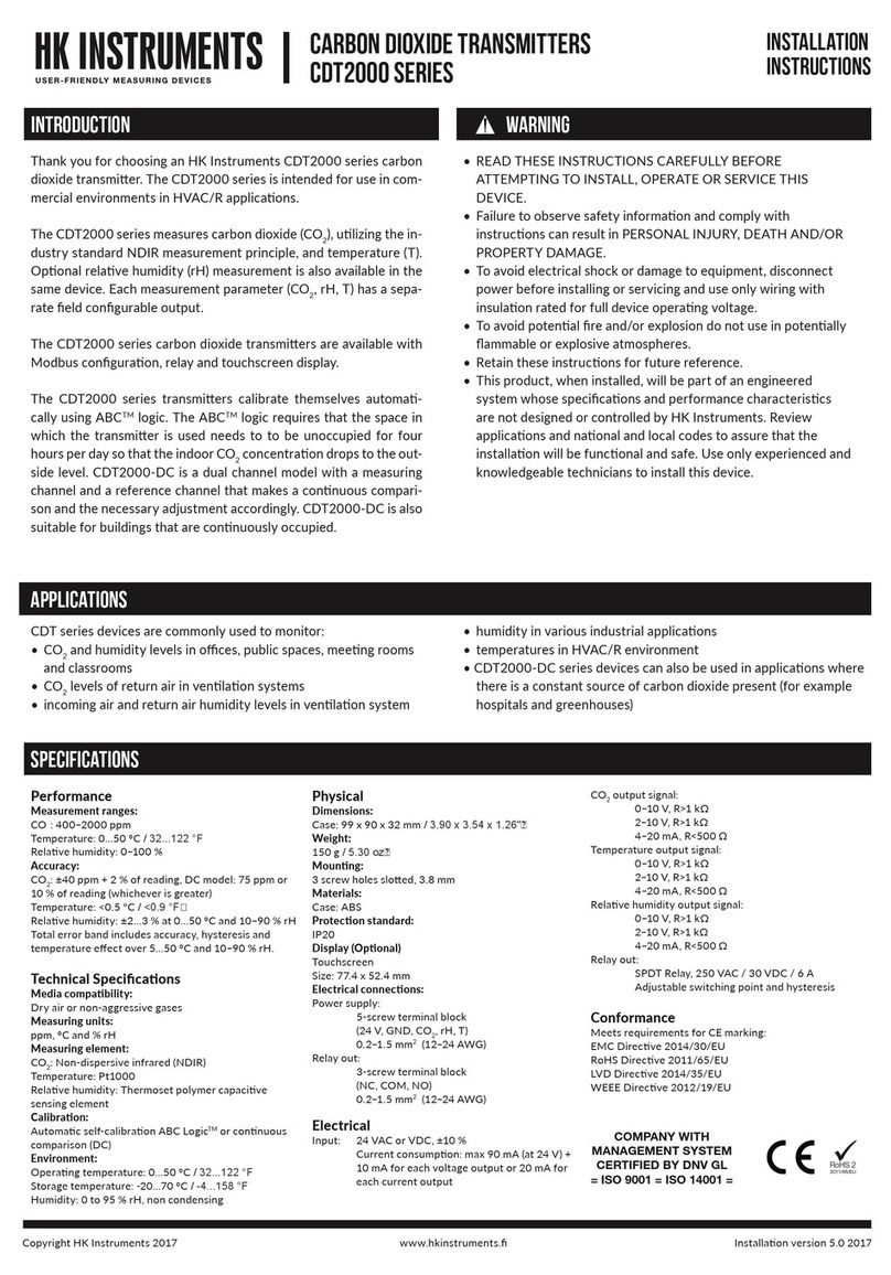
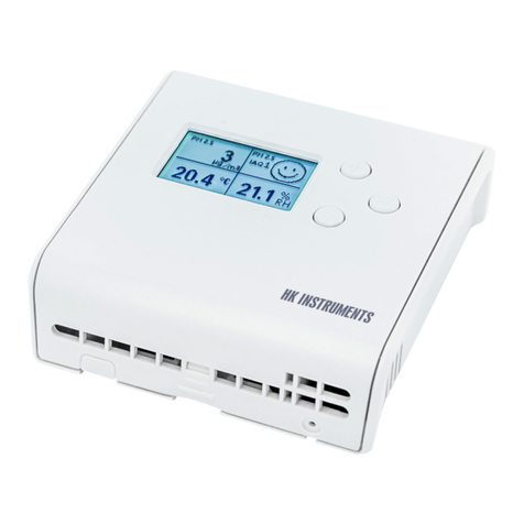
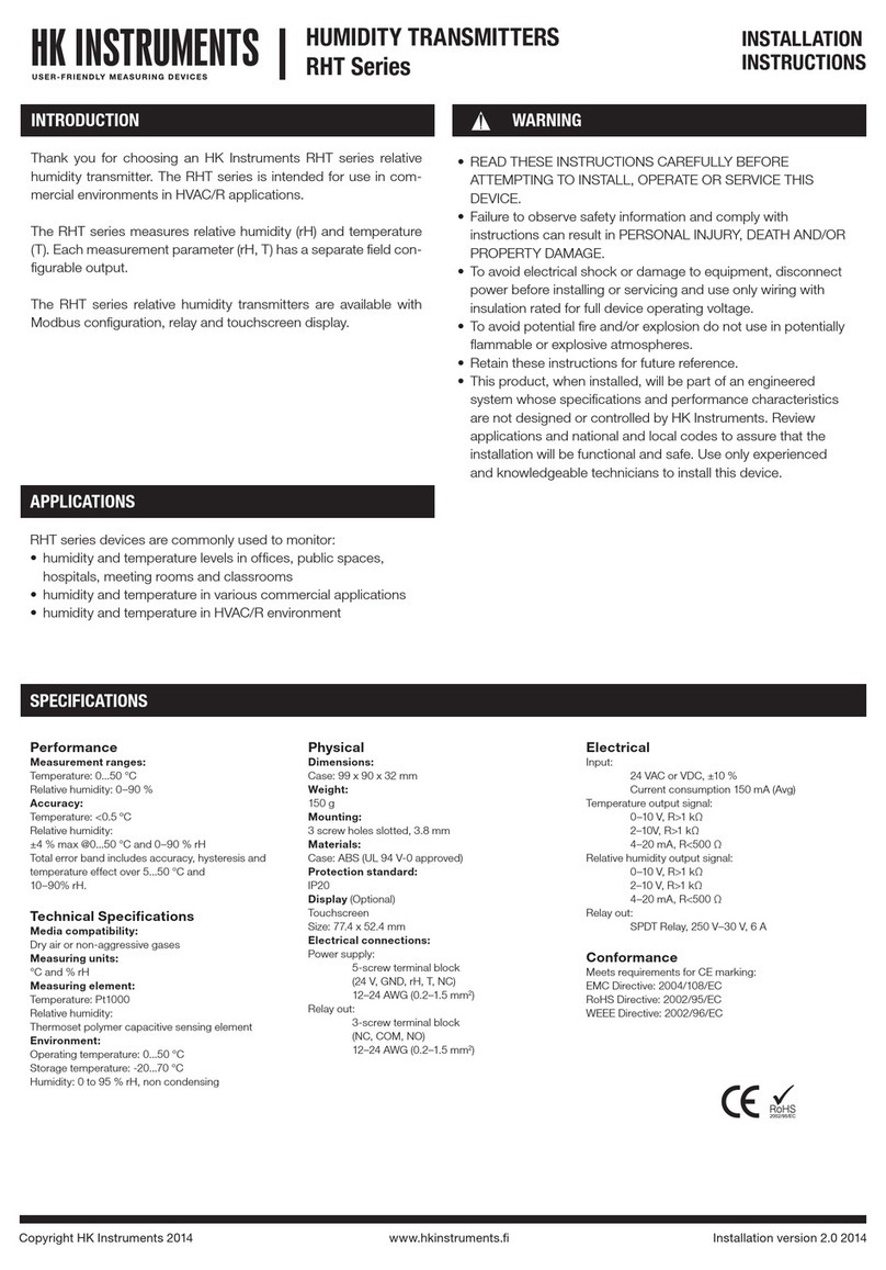
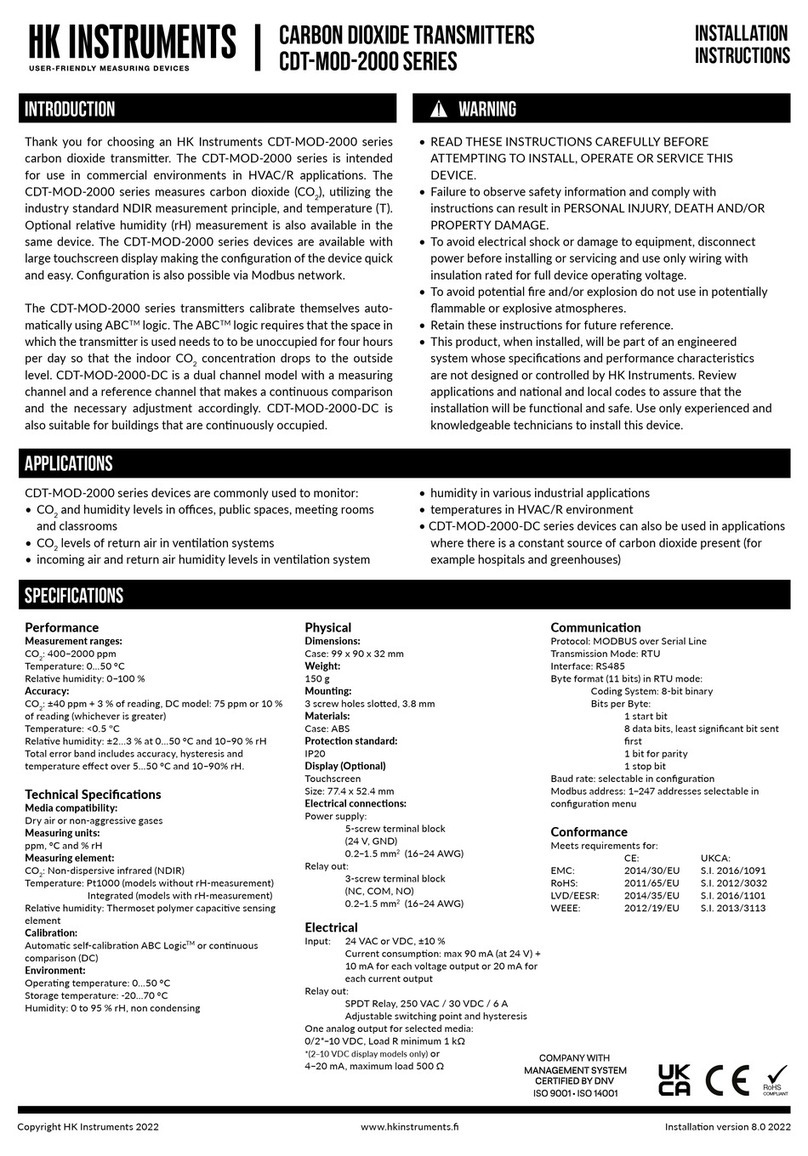
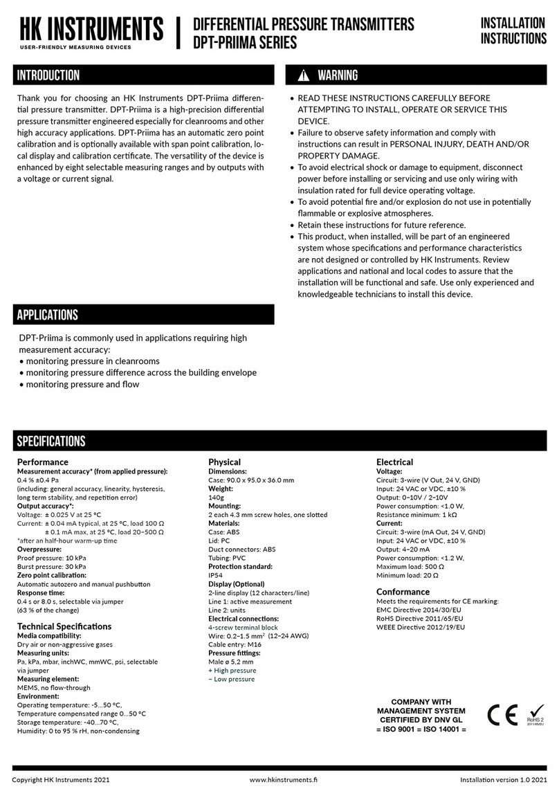
Thank you for choosing an HK Instruments CDT2000 series carbon
dioxide transmitter. The CDT2000 series is intended for use in com-
mercial environments in HVAC/R applications.
The CDT2000 series measures carbon dioxide (CO2), utilizing the in-
dustry standard NDIR measurement principle, and temperature (T).
Optional relative humidity (rH) measurement is also available in the
same device. Each measurement parameter (CO2, rH, T) has a sepa-
rate field configurable output.
The CDT2000 series carbon dioxide transmitters are available with
Modbus configuration, relay, touchscreen display, and NIST standard
calibration certificates.
The CDT2000 series transmitters calibrate themselves automatically
using ABCTM logic. The ABCTM logic requires that the space in which
the transmitter is used needs to to be unoccupied for four hours per
day so that the indoor CO2concentration drops to the outside level.
CDT2000-DC is a dual channel model with a measuring channel and
a reference channel that makes a continuous comparison and the
necessary adjustment accordingly. CDT2000-DC is also suitable for
buildings that are continuously occupied.
SPECIFICATIONS
Performance
Measurement range:
CO2: 400–2,000 ppm
Temperature: 32−122 °F
Relative Humidity: 0–90 %
Accuracy:
CO2: ±40 ppm + 2 % of reading, DC model: 75 ppm or
10 % of reading (whichever is greater)
Temperature: <0.9 °F
Relative Humidity: ±4 % max @32−122 °F
and 0–90 % rH
Total error band includes accuracy, hysteresis and
temperature effect over 41–122 °F and
10–90 % rH.
Technical Specifications
Media Compatibility:
Dry air or non-aggressive gases
Measuring units:
ppm, °F and %
Measuring element:
CO2: Non Dispersive Infrared (NDIR)
Temperature: Pt1000
Relative Humidity: Thermoset polymer capacitive
sensing element
Environment:
Operating Temperature: 32−122 °F (0−50 °C)
Storage Temperature: -4−158 °F (-20−70 °C)
Humidity: 0 to 95 % rH, non condensing
Physical
Case:
Dimensions: 3.93” x 3.57” x 1.26”
(99.87 x 90.75 x 31.99 mm)
Weight: 4.82 oz (150 g)
Mounting: 3 screw holes slotted, 11/64” ø (3.8 mm)
Materials: Case: ABS (UL 94 V-0 Approved)
Protection standard: IP20
Display (Optional)
Touchscreen
Size: 3.05” W x 2.06” H
(77.4 x 52.4 mm)
Electrical Connections:
Power Supply: 5-screw terminal block
(24 V, GND, CO2, rH, Temp)
12–24 AWG (0.2–1.5 mm2)
Relay Out: 3-screw terminal block
(NC, COM, NO)
12–24 AWG (0.2–1.5 mm2)
Electrical
Input: 24 VAC or VDC, ±10 %
Current consumption: max 90 mA (at 24 V) + 10 mA for
each voltage output or 20 mA for each current output
CO2Output signal:
0–10 V, R>1 kΩ
2–10 V, R>1 kΩ
4–20mA, R<500 Ω
Temperature Output signal:
0–10 V, R>1 kΩ
2–10 V, R>1 kΩ
4–20 mA, R<500 Ω
Relative Humidity Output Signal:
0–10 V, R>1 kΩ
2–10 V, R>1 kΩ
4–20 mA, R<500 Ω
Relay Out:
3-screw terminal block
(NC, COM, NO)
12–24 AWG (0.2–1.5 mm2)
SPDT Relay, 250 VAC / 30 VDC / 6 A
Conformance
Meets requirements for CE marking:
EMC Directive: 2014/30/EU
RoHS Directive: 2011/65/EU
LVD Directive: 2014/35/EU
WEEE Directive: 2012/19/EU
INTRODUCTION WARNING
AVERTISSEMENT
• LISEZ ATTENTIVEMENT CES INSTRUCTIONS AVANT DE PROCÉDER À
L’INSTALLATION, LA MISE EN SERVICE OU L’ENTRETIEN DE CET APPAREIL.
• Le non-respect des informations et instructions de sécurité peut entraîner DES
DOMMAGES CORPORELS, LA MORT ET/OU DES DÉGÂTS MATÉRIELS.
• Afin d’éviter les chocs électriques et les dommages matériels, déconnectez
l’alimentation électrique avant l’installation ou l’entretien, et utilisez uniquement du
câblage avec isolement assigné pour une tension d’alimentation optimale.
• Afin de prévenir les risques d’incendie et/ou d’explosion, n’utilisez pas l’appareil
dans des environnements potentiellement inflammables ou explosifs.
• Conservez ces instructions à titre de référence.
• Une fois installé, ce produit fera partie d’un système technique dont les
spécifications et les caractéristiques de performance ne sont ni conçues ni
contrôlées par HK Instruments. Consultez les applications et les codes nationaux
et locaux pour garantir le fonctionnement correct et sûr de l’installation. Ne faites
appel qu’à des techniciens expérimentés et compétents pour installer cet appareil.
APPLICATIONS
• humidity in various industrial applications
• temperatures in HVAC/R environment
• CDT2000-DC series devices can also be used in applications
where there is a constant source of carbon dioxide present (for
example hospitals and greenhouses)
CDT series devices are commonly used to monitor:
• CO2and humidity levels in offices, public spaces, meeting
rooms and classrooms
• CO2levels of extract air in ventilation systems
• supply air and extract air humidity levels in ventilation system
RoHS 2
2011/65/EU
COMPANY WITH
MANAGEMENT SYSTEM
CERTIFIED BY DNV GL

= ISO 9001 = ISO 14001 =
Copyright HK Instruments, Inc. 2017 www.hkinstrumentsinc.com Installation version 2.0 2017
SCHEMATICS
DIMENSIONAL DRAWINGS
Figure 1 - Surface mounting
Display locking
jumper
Output mode
selection
jumpers
Contact pins for
relay terminal
Contact pins for
terminal block
Terminal block
Terminal block for relay
3.89 (99.0)
3.54 (90.0)
3.26 (83.0)
1.948 (49.5)
0.55
(14.0)
1.77 (45.0)
0.708
(18.0)
Ø 0.157
(4.0)
1.26 (32.0)
inch (mm)
INSTALLATION
1) Mount the device in the desired location (see step 1).
2) Route the cables and connect the wires (see step 2).
3) The device is now ready for configuration.
WARNING! Apply power only after the device is properly wired.
STEP 1: MOUNTING THE DEVICE
1) Select a mounting location on the wall at 4 ft (1.2 m) above the
floor. Locate the unit in an area with good ventilation and an
average temperature, where it will be responsive to changes to
the room conditions. The CDT may be mounted on a flat surface.
Do not locate the CDT where it can be effected by:
• Direct sunlight
• Drafts or dead areas behind doors
• Radiant heat from appliances
• Concealed pipes or chimneys
• Outside walls or unheated / uncooled areas
2) Use the device as a template and mark the screw holes.
3) Mount the wall plate with screws. (not included)
Copyright HK Instruments, Inc. 2017 www.hkinstrumentsinc.com Installation version 2.0 2017
Figure 2c - Wiring diagram: relay
NC
COM
NO
Figure 3 - Jumper installation
STEP 2: WIRING DIAGRAMS
CAUTION!
• For CE compliance, a properly grounded shielding cable is
required.
• Use copper wire only. Insulate or wire nut all unused leads.
• Supply a separate cable for relay and signal out when using line
voltage to power the relay.
• Any wiring may carry the full operating line voltage current based
on field installation. The cover locking screw must be installed if
the line voltage is supplied to the relay.
• Care should be used to avoid electrostatic discharge to the
device.
• This unit has configuration jumpers. You may need to reconfigure
this device for your application.
1) Route the cables through the square opening in the back plate or
for surface wiring select a knockout on the top or bottom of the
wall plate, as shown in Figure 2a.
2) Connect the wires as shown in Figure 2b and 2c.
Figure 2b - Wiring diagram:
Power input and signal out
24 V
GND
CO2
rH
Temp
+
Output 0/2–10 V / 4–20 mA
WIRING DIAGRAMS CONTINUED
Figure 2a - Routing the cables
Wires can be routed through the square opening in the back plate
Wires can be routed through the top knockouts
Wires can be routed through the bottom knockouts
STEP 3: CONFIGURATION
NOTE! When using long connection wires it may be necessary
to use a separate GND wire for voltage output current to prevent
measurement distortion. The need for an extra GND wire depends
on the cross section and length of the used connection wires. If long
and/or small cross section wires are used, supply current and wire
resistance may generate a voltage drop in the common GND wire
resulting in a distorted output measurement.
Configuration of the CDT series device consists of:
1) Configuring the jumpers (see step 4).
2) Configuration menu options.
(Display versions only. See the user manual for further details.)
(Grey colour indicates that a jumper is installed)
No jumper
Circuit open
Jumper installed
Circuit closed
Jumper stored
Copyright HK Instruments, Inc. 2017 www.hkinstrumentsinc.com Installation version 2.0 2017
HK Instruments, Inc. (HK)
(a) WARRANTY COVERAGE: HK warrants to the original end user of the Products that
the Products will, at the date of initial purchase, meet the applicable specification for
such Products (as described by HK in its product literature) and, under normal use and
service, will be free from any defects in materials or manufacture for (a) one (1) year
from date of sale to end user for electromechanical Products and (b) five (5) years from
date of manufacture for electronic Products.
(b) NO WARRANTY OF PRODUCT SUITABILITY: Neither HK nor the manufacturer of
the Products to be sold hereunder (“Manufacturer”) makes any warranty that Products
are suitable for a particular purpose, application or design. Many states and localities
have differing codes or regulations governing the installation and/or use of HK
products. HK does not guarantee compliance with such codes or regulations; the end
user is solely responsible for safe and correct installation and use of the Products and
for compliance with such codes and regulations.
(c) EXCLUSION OF IMPLIED WARRANTIES: THE WARRANTY HEREIN IS THE
ONLY WARRANTY APPLICABLE TO THE PRODUCTS AND EXCLUDES ALL OTHER
WARRANTIES, INCLUDING ANY WARRANTY OF MERCHANTABILITY OR FITNESS
FOR A PARTICULAR PURPOSE, AND ANY IMPLIED WARRANTY ARISING FROM
COURSE OF DEALING OR USAGE OF TRADE.
(d) REMEDIES FOR NON-CONFORMITY OR BREACH OF WARRANTY: If the Product
purchased does not conform to the applicable warranty, HK will provide, at its
option, one of the following remedies: (1) repair of the non-conforming Product, (2)
replacement with a conforming Product, or (3) refund of the original purchase price.
THESE REMEDIES SHALL BE THE EXCLUSIVE AND SOLE REMEDY for any breach
of warranty. HK and Manufacturer have no other responsibility or liability for breach of
warranty or otherwise.
(e) LIMITATION OF LIABILITY: NEITHER HK NOR MANUFACTURER WILL BE LIABLE
FOR ANY INCIDENTAL, SPECIAL, INDIRECT, OR CONSEQUENTIAL DAMAGES
UNDER ANY CIRCUMSTANCE, INCLUDING WITHOUT LIMITATION ANY DEFECT IN
THE PRODUCT PURCHASED.
(f) FURTHER LIMITATIONS: The warranty herein does not cover damage caused
by lightning, flood or other natural phenomenon; normal wear and tear; accident,
improper or careless handling, abnormal use, overloading, improper storage or abuse;
incorrect installation, care or reconstruction; or alteration, calibration, reconfiguration,
maintenance or installation work done by unqualified personnel. Should Manufacturer
alter the structure of any Product in the future, HK and Manufacturer shall not be
obligated to make comparable changes to Products already purchased. HK will give
a new warranty for Products being replaced or repaired within the warranty period,
however only to the expiration of the original Product’s warranty period. The warranty
includes the repair of a defective part or device, or if needed, a new part or device, but
no other costs except as otherwise stated in the HK Distributor Terms and Conditions.
The parts left over from installation should be
recycled according to your local instructions.
Decommissioned devices should be taken to
a recycling site that specializes in electronic
waste.
RECYCLING/DISPOSAL
WARRANTY POLICY
STEP 4: SELECTING THE OUTPUT MODE
1) Configuration of the output modes of:
• Carbon dioxide (CO2)
• Relative humidity (rH)
• Temperature (Temp)
Select the output mode, current (4–20 mA) or voltage (0–10 V),
by installing jumpers as shown in Figure 4. Each output, CO2,
relative humidity, and temperature are configured separately.
To select 2–10 V output mode on a display version of the device:
First, select 0–10 V output by jumper(s), then change the voltage (V)
output from 0–10 V to 2–10 V via the configuration menu. Please
see the user manual for more details.
Figure 4
Jumper installed to the left side pins:
0–10 V output selected
CO2
rH
Temp
0–10 V 4–20 mA
Jumper installed to the right side pins:
4–20 mA output selected
CO2
rH
Temp
0–10 V 4–20 mA
First jumper installed to the right side pins:
4–20 mA output selected for CO2
Second and third jumper installed to the left side pins
0–10 V outputs selected for relative humidity & temperature
CO2
rH
Temp
0–10 V 4–20 mA
2) Locking the display:
Install the jumper to lock the display to prevent access to the configu-
ration menu after installation is completed (see the schematics for the
location of the pins).

Other HK Instruments Transmitter manuals

HK Instruments DPT-IO-MOD Series User manual

HK Instruments

HK Instruments DPT-IO-MOD Series User manual

HK Instruments CDT2000 Series User manual

HK Instruments

HK Instruments CDT2000 Series User manual

HK Instruments RHT-MOD Duct Series User manual

HK Instruments

HK Instruments RHT-MOD Duct Series User manual

HK Instruments CDT-MOD-2000 Duct Series User manual

HK Instruments

HK Instruments CDT-MOD-2000 Duct Series User manual

HK Instruments DPT-CR-MOD Series User manual

HK Instruments

HK Instruments DPT-CR-MOD Series User manual

HK Instruments CDT-MOD-2000 Series User manual

HK Instruments

HK Instruments CDT-MOD-2000 Series User manual

HK Instruments DPT-MOD Series User manual

HK Instruments

HK Instruments DPT-MOD Series User manual

HK Instruments DPT-MOD Series User manual

HK Instruments

HK Instruments DPT-MOD Series User manual

HK Instruments CDT-MOD-2000 Series User manual

HK Instruments

HK Instruments CDT-MOD-2000 Series User manual

HK Instruments RHT-MOD Duct Series User manual

HK Instruments

HK Instruments RHT-MOD Duct Series User manual

HK Instruments DPT-Dual-MOD Series User manual

HK Instruments

HK Instruments DPT-Dual-MOD Series User manual

HK Instruments DPT-Ctrl-MOD Series User manual

HK Instruments

HK Instruments DPT-Ctrl-MOD Series User manual

HK Instruments RHT Series User manual

HK Instruments

HK Instruments RHT Series User manual

HK Instruments DPT-Priima Series User manual

HK Instruments

HK Instruments DPT-Priima Series User manual

HK Instruments SIRO Series User manual

HK Instruments

HK Instruments SIRO Series User manual

HK Instruments DPT-Flow-1000 Quick start guide

HK Instruments

HK Instruments DPT-Flow-1000 Quick start guide

HK Instruments DPT-Dual-MOD Series User manual

HK Instruments

HK Instruments DPT-Dual-MOD Series User manual

HK Instruments AVT Series User manual

HK Instruments

HK Instruments AVT Series User manual

HK Instruments DPT-2W- 100-R2 User manual

HK Instruments

HK Instruments DPT-2W- 100-R2 User manual

HK Instruments DPT-Flow Series User manual

HK Instruments

HK Instruments DPT-Flow Series User manual

HK Instruments KLU 100 User manual

HK Instruments

HK Instruments KLU 100 User manual

HK Instruments DPT-MOD Series User manual

HK Instruments

HK Instruments DPT-MOD Series User manual

HK Instruments DPT-Priima Series User manual

HK Instruments

HK Instruments DPT-Priima Series User manual

HK Instruments AVT Series User manual

HK Instruments

HK Instruments AVT Series User manual

Popular Transmitter manuals by other brands

Vega VEGABAR 86 Quick setup guide

Vega

Vega VEGABAR 86 Quick setup guide

BWI Eagle AIR-EAGLE XLT 441-HH-2-VBR manual

BWI Eagle

BWI Eagle AIR-EAGLE XLT 441-HH-2-VBR manual

Quantec QT412RXA instructions

Quantec

Quantec QT412RXA instructions

Siemens SITRANS P 7MF1562 operating instructions

Siemens

Siemens SITRANS P 7MF1562 operating instructions

WisyCom MTB40 user manual

WisyCom

WisyCom MTB40 user manual

Eaton Scantronic 701r manual

Eaton

Eaton Scantronic 701r manual

Danfoss TM70 Calibration guide

Danfoss

Danfoss TM70 Calibration guide

WEVI CW-5 operating instructions

WEVI

WEVI CW-5 operating instructions

Emerson Rosemount OCX 8800 quick start guide

Emerson

Emerson Rosemount OCX 8800 quick start guide

RKI Instruments 65-2405RK-04 Operator's manual

RKI Instruments

RKI Instruments 65-2405RK-04 Operator's manual

Extron electronics DTP T HWP D Series user guide

Extron electronics

Extron electronics DTP T HWP D Series user guide

SenseAir tSENSE VAV Disp user manual

SenseAir

SenseAir tSENSE VAV Disp user manual

Comet W0854P quick start guide

Comet

Comet W0854P quick start guide

Nulaxy NX16 user manual

Nulaxy

Nulaxy NX16 user manual

FISCHER DE85 operating manual

FISCHER

FISCHER DE85 operating manual

Nautel ND500II Information sheet

Nautel

Nautel ND500II Information sheet

Williams AV PPA T46 quick start guide

Williams AV

Williams AV PPA T46 quick start guide

M-system SENTRONIC M2SES quick start guide

M-system

M-system SENTRONIC M2SES quick start guide

manuals.online logo
manuals.online logoBrands
  • About & Mission
  • Contact us
  • Privacy Policy
  • Terms and Conditions

Copyright 2025 Manuals.Online. All Rights Reserved.