manuals.online logo
Brands
  1. Home
  2. •
  3. Brands
  4. •
  5. HK Instruments
  6. •
  7. Transmitter
  8. •
  9. HK Instruments AVT Series User manual

HK Instruments AVT Series User manual

Copyright HK Instruments, Inc. 2017 www.hkinstrumentsinc.com Installation version 2.0 2017
INSTALLATION
INSTRUCTIONS
AIR FLOW AND VELOCITY TRANSMITTERS
AVT Series
• READ THESE INSTRUCTIONS CAREFULLY BEFORE ATTEMPTING TO
INSTALL, OPERATE OR SERVICE THIS DEVICE.
• Failure to observe safety information and comply with instructions can result in
PERSONAL INJURY, DEATH AND/OR PROPERTY DAMAGE.
• To avoid electrical shock or damage to equipment, disconnect power before
installing or servicing and use only wiring with insulation rated for full device
operating voltage.
• To avoid potential fire and/or explosion do not use in potentially flammable or
explosive atmospheres.
• Retain these instructions for future reference.
• This product, when installed, will be part of an engineered system whose
specifications and performance characteristics are not designed or controlled
by HK Instruments. Review applications and national and local codes to assure
that the installation will be functional and safe. Use only experienced and
knowledgeable technicians to install this device.
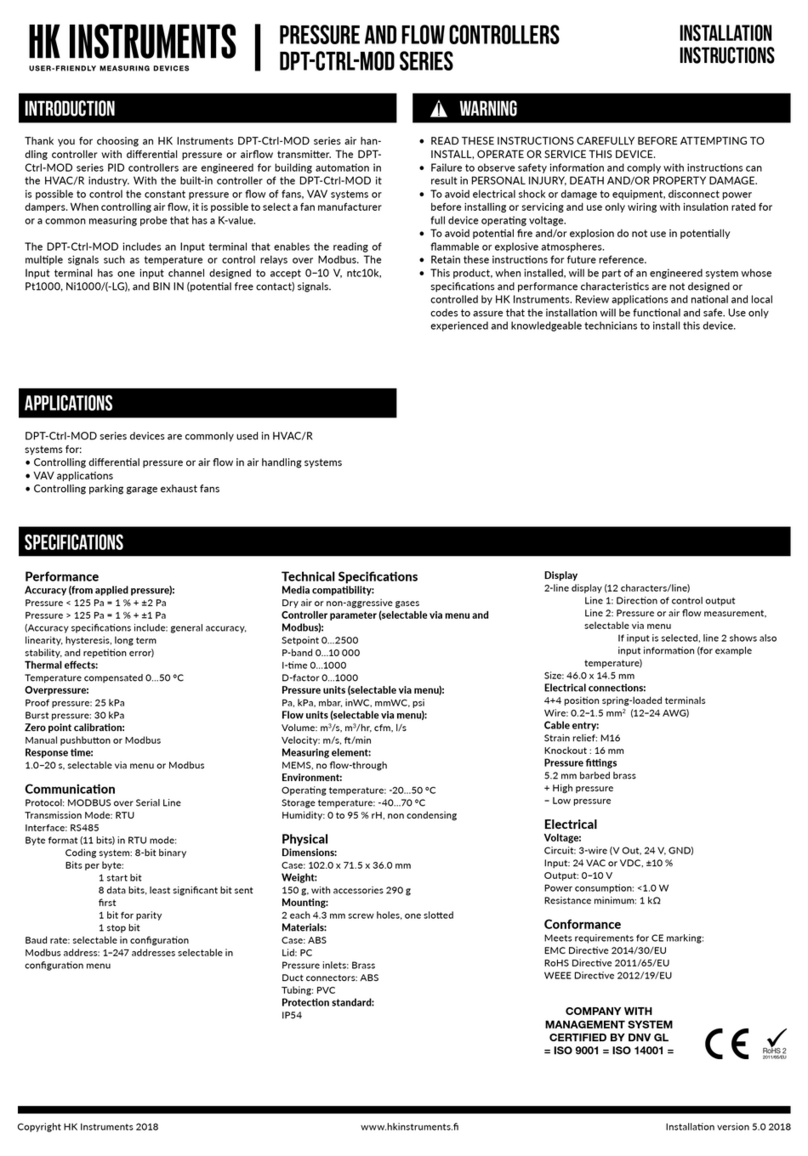
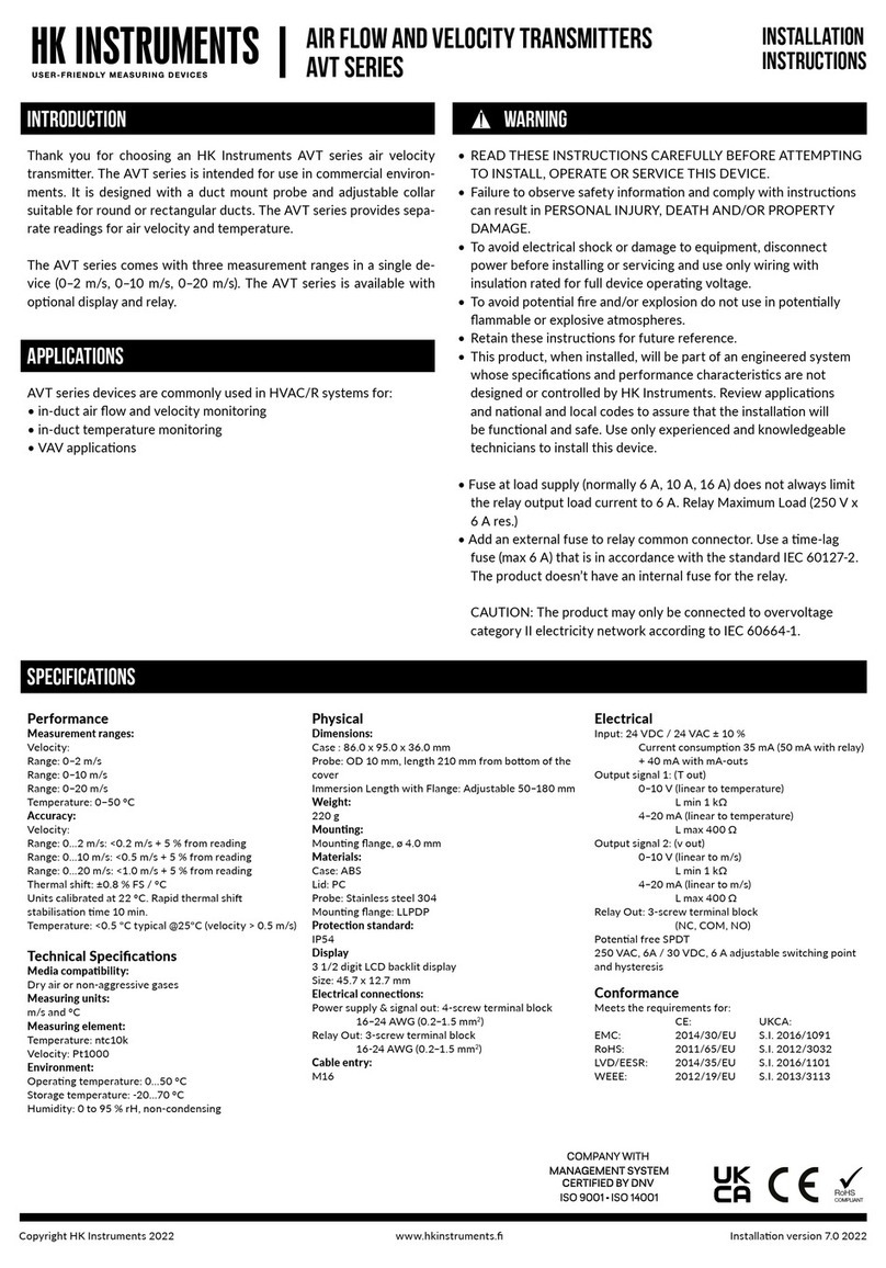
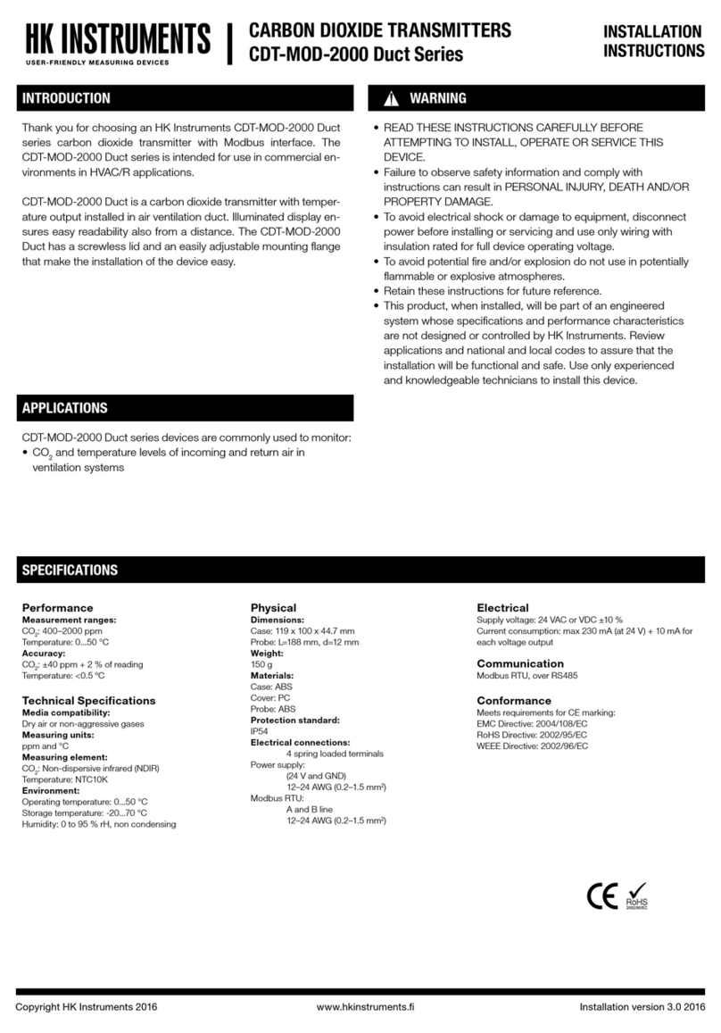
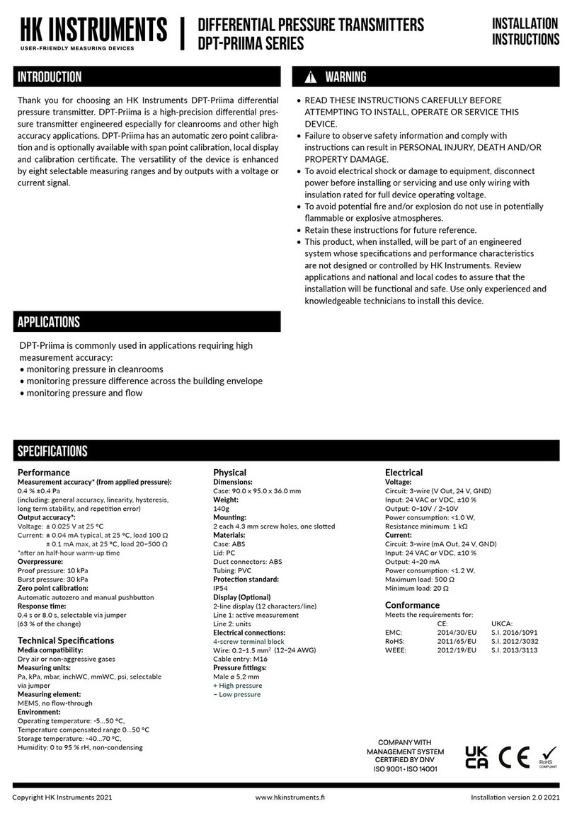
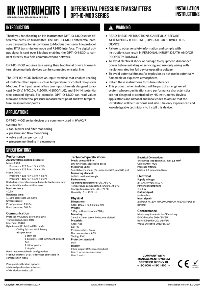
Thank you for choosing an HK Instruments AVT series air veloc-
ity transmitter. The AVT series is intended for use in commercial
environments. It is designed with a duct mount probe and adjust-
able collar suitable for round or rectangular ducts. The AVT series
provides separate readings for air velocity and temperature.
The AVT series comes with three measurement ranges in a single
device (0–400, 0–2000 and 0–4000 FPM). The AVT series is avail-
able with a relay and NIST standard calibration certificates.
SPECIFICATIONS
Performance
Measurement ranges:
Velocity: Range 2: 0–400 fpm
Range 10: 0–2,000 fpm
Range 20: 0–4,000 fpm
Temperature: 32−122 °F (0−50 °C)
Accuracy:
Velocity: Range 2: 0–400 fpm
<20 fpm +5 % from reading
Range 10: 0–2,000 fpm
<100 fpm +5 % from reading
Range 20: 0–4,000 fpm
<200 fpm +5 % from reading
Temperature: <0.9 ºF for v > 100 fpm
Accuracy specifications include: general accuracy,
temperature drift, linearity, hysteresis, long term
stability, and repetition error.
Technical Specifications
Media compatibility:
Dry air or non-aggressive gases
Measuring units:
fpm and °F
Measuring element:
Temperature: ntc10k
Velocity: Pt1000
Environment:
Operating temperature: 32−122 °F (0−50 °C)
Storage temperature: -4−158 °F (-20−70 °C)
Humidity: 0 to 95 % rH, non condensing
Physical
Case:
Dimensions: 3.54” x 3.74” x 1.4”
(90.0 x 95.0 x 36.0 mm)
Dimensions - Probe:
OD: 0.394 in (10 mm)
Length: 8.26 in (210 mm) from bottom of the cover
Immersion length with flange: Adjustable 2”–7.08”
(50–180 mm)
Weight (Case + Probe): 7.76 oz (220 g)
Mounting: 2 screw holes, 11/64” (4.0 mm)
Materials:
Case: ABS (UL 94 V-0 Approved)
Lid: PC (UL 94 V-1 Approved)
Probe: Stainless Steel
Protection standard: IP54 / NEMA3
Display
3 1/2 digit LCD display
Size: 1.8” x 0.5” (45.7 x 12.7 mm)
Electrical connections: (2 each)
Power supply & signal out: 4-screw terminal block
12–24 AWG (0.2–1.5 mm2)
Relay out: 3-screw terminal block
12–24 AWG (0.2–1.5 mm2)
Cable entry: (2 each)
Strain relief: M16
Knockout : 0.625” (16 mm)
Electrical
Input: 24 VDC / 24 VAC ± 10 %
Current consumption 35 mA (50 mA with relay) +
40 mA with mA outputs
Output signal 1: (temperature out)
0–10 V (linear to temperature)
L min 1 kΩ
4–20 mA (linear to temperature)
L max 400 Ω
Output signal 2: (velocity out)
0–10 V (linear to fpm)
L min 1 kΩ
4–20 mA (linear to fpm)
L max 400 Ω
Relay Out: 3 screw terminal block
(NC, COM, NO)
12–24 AWG (0.2–1.5 mm2)
Potential free SPDT
250 VAC, 6 A / 30 VDC, 6 A adjustable switching point
and hysteresis
Conformance
Meets requirements for CE marking:
EMC Directive 2014/30/EU
RoHS Directive 2011/65/EU
Meets safety requirements for electrical equipment for
measurement, control, and laboratory use:
ETL marking, standard IEC61010-1.
Product is tested and meets the NRTL product approval
requirements.
INTRODUCTION WARNING
AVERTISSEMENT
• LISEZ ATTENTIVEMENT CES INSTRUCTIONS AVANT DE PROCÉDER À
L’INSTALLATION, LA MISE EN SERVICE OU L’ENTRETIEN DE CET APPAREIL.
• Le non-respect des informations et instructions de sécurité peut entraîner DES
DOMMAGES CORPORELS, LA MORT ET/OU DES DÉGÂTS MATÉRIELS.
• Afin d’éviter les chocs électriques et les dommages matériels, déconnectez
l’alimentation électrique avant l’installation ou l’entretien, et utilisez uniquement du
câblage avec isolement assigné pour une tension d’alimentation optimale.
• Afin de prévenir les risques d’incendie et/ou d’explosion, n’utilisez pas l’appareil
dans des environnements potentiellement inflammables ou explosifs.
• Conservez ces instructions à titre de référence.
• Une fois installé, ce produit fera partie d’un système technique dont les
spécifications et les caractéristiques de performance ne sont ni conçues ni
contrôlées par HK Instruments. Consultez les applications et les codes nationaux
et locaux pour garantir le fonctionnement correct et sûr de l’installation. Ne faites
appel qu’à des techniciens expérimentés et compétents pour installer cet appareil.
APPLICATIONS
AVT series devices are commonly used in HVAC/R systems for:
• in-duct air flow and velocity monitoring
• in-duct temperature monitoring
• VAV applications
RoHS 2
2011/65/EU
4002576
Conforms to ANSI/UL Std 61010
Certified to CAN/CSA Std C22.2 No 61010
COMPANY WITH
MANAGEMENT SYSTEM
CERTIFIED BY DNV GL
= ISO 9001 = ISO 14001 =
Copyright HK Instruments, Inc. 2017 www.hkinstrumentsinc.com Installation version 2.0 2017
SCHEMATICS
DIMENSIONAL DRAWINGS
Figure 1c - Mounting orientation
Figure 1a - Mounting a flange
Figure 1b - Mounting the probe in a flange
Joystick Terminal
block
Jumpers
Terminal block
for relay
T
vTout
vout
24V
GND
V mA
sw.p.
hyst.
J1
J2
Display
AVT
3.54
(90.0)
2.815
(71.5)
1.41
(36.0)
3.74
(95.0)
0.59
(15.0)
0.59
(15.0)
2.756
(70.0)
8.267
(210.0)
Temperature
Sensor
Velocity Sensor
INSTALLATION
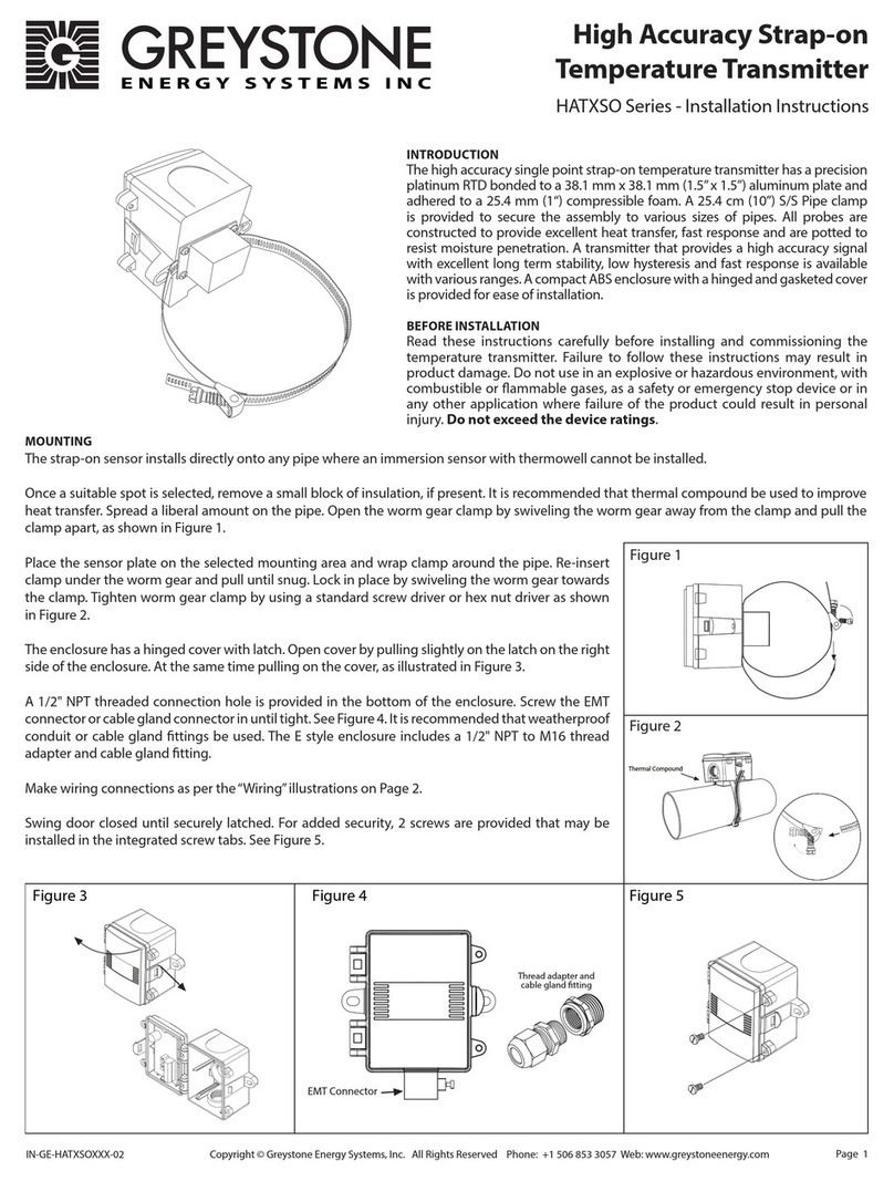
1) Mount the device in the desired location (see step 1).
2) Open the lid and route the cable through the strain relief and
connect the wires to the terminal block (see step 2).
3) The device is now ready for configuration.
WARNING! Apply power only after the device is properly wired.
STEP 1: MOUNTING THE DEVICE
1) Select the mounting location (on a duct).
2) Use the mounting flange of the device as a template and mark
the screw holes.
3) Mount the flange on the duct with screws (not included). (Figure 1a)
4) Adjust the probe to the desired depth. Ensure that the end of the
probe reaches the middle of the duct. (Figure 1b)
5) Tighten the screw on the flange to hold the probe in position.
Tighten the
screw
Air ow direction Air ow direction
Air ow direction Air ow direction Air ow direction
Strain relief facing down
Copyright HK Instruments, Inc. 2017 www.hkinstrumentsinc.com Installation version 2.0 2017
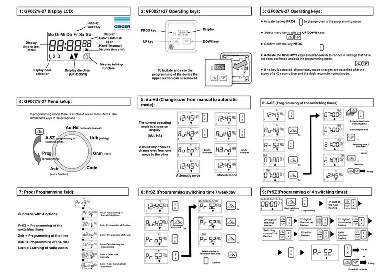
CONFIGURATION
Configuration requires:
1) Selecting the desired measurement mode, step 3.
2) Selecting the desired measurement range, step 4.
3) Configuring the relay (optional), steps 5 and 6.
Selection convention used to input configuration
information into AVT transmitter.
Entering the configuration information into the AVT transmitter
is accomplished with the joystick, the display, and the jumpers
installed and removed from the set of three (3) or four (4) jumper
pins, see Figure 3 and schematics.
Figure 2b - Wiring diagram relay output
NC
COM
NO
Figure 3 - Jumper installation
STEP 2: WIRING DIAGRAMS
STEP 3: SELECTING THE MEASUREMENT MODE
For CE compliance a properly grounded shielding cable is
required.
1) Unscrew the strain relief and route the cable(s). Use the strain
relief on the left for power in and signal out (Tout/vout) and the
strain relief on the right for relay.
2) Connect the wires as shown in figure 2a and 2b.
3) Tighten the strain relief.
Figure 2a - Wiring diagram: Tout & Vout
Tout
vout
24 V
GND
+Power supply
24 VDC / 24 VAC
V A VA
Output 0...10 V / 4...20 mA (temperature)
Output 0...10 V / 4...20 mA (velocity)
CONFIGURATION CONTINUED
Pressing down or tilting (tilt up/down or side-to-
side) will cycle the display though the available
menu choices. The joystick will only cycle the
choices up. If you accidently pass your preferred
selection continue to activate the joystick until
your selection reappears.
Jumpers are used in two (2) different ways:
1. Jumpers are installed, and remain installed, to
select the required choice, see Steps 3 and 4.
2. Jumpers are installed, a choice is made, and
the jumper is removed, see Steps 5 and 6.
Joystick
Jumpers
No jumper
Circuit open
Jumper storedJumper installed
Cicuit closed
(Grey colour indicates that a jumper is installed)
Configure the outputs:
• Temperature output (Tout)
• Velocity output (vout)
Select the output mode, current (mA) or voltage (V), by installing
jumpers as shown in Figure 4. Both outputs, temperature (T) and
velocity (V), are configured separately.
Figure 4
V
Temperature output (Tout): T = voltage (V)
Velocity output (vout): v = voltage (V)
T
v
mA
V
Temperature output (Tout): T = current (mA)
Velocity output (vout): v = current (mA)
T
v
mA
Temperature output (Tout): T = voltage (V)
Velocity output (vout): v = current (mA)
T
v
V mA
Temperature output (Tout): T = current (mA)
Velocity output (vout): v = voltage (V)
T
v
V mA
STEP 4: SELECTING THE MEASUREMENT RANGE
Select the measurement range by installing jumpers as shown in
Figure 5. (Note: Figure 3, Jumper installation)
Figure 5
J1 Jumper (J1): Installed
J2 Jumper (J2): Not installed
Range 2 (0–400 fpm) (0–2 m/s)
J1 Jumper (J1): Not installed
J2 Jumper (J2): Installed
Range 10 (0–2000 FPM) (0–10 m/s)
J1 Jumper (J1): Installed
J2 Jumper (J2): Installed
Range 20 (0–4000 FPM) (0–20 m/s)
Copyright HK Instruments, Inc. 2017 www.hkinstrumentsinc.com Installation version 2.0 2017
HK Instruments, Inc. (HK)
(a) WARRANTY COVERAGE: HK warrants to the original end user of the Products that
the Products will, at the date of initial purchase, meet the applicable specification for
such Products (as described by HK in its product literature) and, under normal use and
service, will be free from any defects in materials or manufacture for (a) one (1) year
from date of sale to end user for electromechanical Products and (b) five (5) years from
date of manufacture for electronic Products.
(b) NO WARRANTY OF PRODUCT SUITABILITY: Neither HK nor the manufacturer of
the Products to be sold hereunder (“Manufacturer”) makes any warranty that Products
are suitable for a particular purpose, application or design. Many states and localities
have differing codes or regulations governing the installation and/or use of HK
products. HK does not guarantee compliance with such codes or regulations; the end
user is solely responsible for safe and correct installation and use of the Products and
for compliance with such codes and regulations.
(c) EXCLUSION OF IMPLIED WARRANTIES: THE WARRANTY HEREIN IS THE
ONLY WARRANTY APPLICABLE TO THE PRODUCTS AND EXCLUDES ALL OTHER
WARRANTIES, INCLUDING ANY WARRANTY OF MERCHANTABILITY OR FITNESS
FOR A PARTICULAR PURPOSE, AND ANY IMPLIED WARRANTY ARISING FROM
COURSE OF DEALING OR USAGE OF TRADE.
(d) REMEDIES FOR NON-CONFORMITY OR BREACH OF WARRANTY: If the Product
purchased does not conform to the applicable warranty, HK will provide, at its
option, one of the following remedies: (1) repair of the non-conforming Product, (2)
replacement with a conforming Product, or (3) refund of the original purchase price.
THESE REMEDIES SHALL BE THE EXCLUSIVE AND SOLE REMEDY for any breach
of warranty. HK and Manufacturer have no other responsibility or liability for breach of
warranty or otherwise.
(e) LIMITATION OF LIABILITY: NEITHER HK NOR MANUFACTURER WILL BE LIABLE
FOR ANY INCIDENTAL, SPECIAL, INDIRECT, OR CONSEQUENTIAL DAMAGES
UNDER ANY CIRCUMSTANCE, INCLUDING WITHOUT LIMITATION ANY DEFECT IN
THE PRODUCT PURCHASED.
(f) FURTHER LIMITATIONS: The warranty herein does not cover damage caused
by lightning, flood or other natural phenomenon; normal wear and tear; accident,
improper or careless handling, abnormal use, overloading, improper storage or abuse;
incorrect installation, care or reconstruction; or alteration, calibration, reconfiguration,
maintenance or installation work done by unqualified personnel. Should Manufacturer
alter the structure of any Product in the future, HK and Manufacturer shall not be
obligated to make comparable changes to Products already purchased. HK will give
a new warranty for Products being replaced or repaired within the warranty period,
however only to the expiration of the original Product’s warranty period. The warranty
includes the repair of a defective part or device, or if needed, a new part or device, but
no other costs except as otherwise stated in the HK Distributor Terms and Conditions.
The parts left over from installation should be
recycled according to your local instructions.
Decommissioned devices should be taken to
a recycling site that specializes in electronic
waste.
RECYCLING/DISPOSAL
WARRANTY POLICY
STEP 5: CONFIGURING THE RELAY SWITCHING POINT (sw.p.)
Note: display is required!
1) Install a jumper to pins labeled sw.p. (switching point), see Figure 6.
2) Press down/tilt the pushbutton (joystick). The values (FPM) for the
switching point (relay on/off) will cycle up. Continue until the re-
quired value (FPM) is shown on the display.
3) Remove and store the jumper after the configuration is completed.
STEP 6: CONFIGURING THE RELAY HYSTERESIS (hyst.)
1) Install a jumper to pins labeled hyst. (hysteresis), see Figure 5.
2) Press down/tilt the pushbutton (joystick). The values (FPM) for the
hysteresis of the relay switching point will cycle up to the maximum
value. Continue until the required value (FPM) is shown on the dis-
play.
3) Remove and store the jumper after the configuration is completed.
About hysteresis
Hysteresis represents a dead-zone less than or equal to 20 % of the
range selected. The hysteresis is anchored at the switching point
(sw.p.), extending to the hysteresis range selected.
| | | | || | |
350 300 250 200 150 100 50 0
sw p.
300 FPM
Hysteresis
=
50 FPM
Dead
zone
In the above example switching point is set at 300 FPM, and hyster-
esis is set at 50 FPM. As the velocity increases over 300 FPM, the re-
lay will open/close. As velocity reduces, the relay will not close/open
until the velocity passes 250 FPM, thus preventing rapid cycling.
Range Maximum Hysteresis
m/s FPM m/s FPM
0–2 0–400 0.4 80
0–10 0–2,000 2 400
0–20 0–4,000 4 800
The hysteresis maximum setting is based on the range selected.
T
v
V mA
sw.p.
hyst.
Tout
vout
24V
GND
J1
J2
Joystick Terminal
block
Jumpers
Terminal block
for relay
Display
Figure 6

Other HK Instruments Transmitter manuals

HK Instruments CMT Series User manual

HK Instruments

HK Instruments CMT Series User manual

HK Instruments DPT-Flow Series User manual

HK Instruments

HK Instruments DPT-Flow Series User manual

HK Instruments DPT-Priima Series User manual

HK Instruments

HK Instruments DPT-Priima Series User manual

HK Instruments DPT-MOD Series User manual

HK Instruments

HK Instruments DPT-MOD Series User manual

HK Instruments DPT-CR-MOD Series User manual

HK Instruments

HK Instruments DPT-CR-MOD Series User manual

HK Instruments DPT-Flow-1000 Quick start guide

HK Instruments

HK Instruments DPT-Flow-1000 Quick start guide

HK Instruments DPT-2W- 100-R2 User manual

HK Instruments

HK Instruments DPT-2W- 100-R2 User manual

HK Instruments RHT Series User manual

HK Instruments

HK Instruments RHT Series User manual

HK Instruments CDT-MOD-2000 Series User manual

HK Instruments

HK Instruments CDT-MOD-2000 Series User manual

HK Instruments RHT-MOD Series User manual

HK Instruments

HK Instruments RHT-MOD Series User manual

HK Instruments DPT-Dual-MOD Series User manual

HK Instruments

HK Instruments DPT-Dual-MOD Series User manual

HK Instruments DPT-Dual-MOD Series User manual

HK Instruments

HK Instruments DPT-Dual-MOD Series User manual

HK Instruments CDT-MOD-2000 Series User manual

HK Instruments

HK Instruments CDT-MOD-2000 Series User manual

HK Instruments DPT-R8 Series User manual

HK Instruments

HK Instruments DPT-R8 Series User manual

HK Instruments RHT DUCT Series User manual

HK Instruments

HK Instruments RHT DUCT Series User manual

HK Instruments SIRO Series User manual

HK Instruments

HK Instruments SIRO Series User manual

HK Instruments DPT-Priima Series User manual

HK Instruments

HK Instruments DPT-Priima Series User manual

HK Instruments DPT-MOD Series User manual

HK Instruments

HK Instruments DPT-MOD Series User manual

HK Instruments Siro-MOD Series User manual

HK Instruments

HK Instruments Siro-MOD Series User manual

HK Instruments DPT-IO-MOD Series User manual

HK Instruments

HK Instruments DPT-IO-MOD Series User manual

HK Instruments RHT-MOD Duct Series User manual

HK Instruments

HK Instruments RHT-MOD Duct Series User manual

HK Instruments DPT2500-R8 Series Instruction manual

HK Instruments

HK Instruments DPT2500-R8 Series Instruction manual

HK Instruments CDT Series User manual

HK Instruments

HK Instruments CDT Series User manual

HK Instruments RHT-MOD Duct Series User manual

HK Instruments

HK Instruments RHT-MOD Duct Series User manual

Popular Transmitter manuals by other brands

Vaisala HUMICAP HMW90 SERIES quick guide

Vaisala

Vaisala HUMICAP HMW90 SERIES quick guide

Burk Plus-X 300 Installation and operation manual

Burk

Burk Plus-X 300 Installation and operation manual

ROHRBACK COSASCO SYSTEMS CORRATER 9020 user manual

ROHRBACK COSASCO SYSTEMS

ROHRBACK COSASCO SYSTEMS CORRATER 9020 user manual

Zigen ZIG-POE-AHTX user manual

Zigen

Zigen ZIG-POE-AHTX user manual

MuxLab SE-000857-C Quick installation guide

MuxLab

MuxLab SE-000857-C Quick installation guide

Transvideo Titan HD Operator's manual

Transvideo

Transvideo Titan HD Operator's manual

RF Central Microlite HD quick start guide

RF Central

RF Central Microlite HD quick start guide

CMOSTEK CMT2157A manual

CMOSTEK

CMOSTEK CMT2157A manual

Emerson Rosemount 3051S Series quick start guide

Emerson

Emerson Rosemount 3051S Series quick start guide

AMG AMG4687BER instruction manual

AMG

AMG AMG4687BER instruction manual

ARMANO HART B74 operating instructions

ARMANO

ARMANO HART B74 operating instructions

Canon Wireless Transmitter WFT-E6A instruction manual

Canon

Canon Wireless Transmitter WFT-E6A instruction manual

Listen LA-326 user manual

Listen

Listen LA-326 user manual

Niko 05-315 quick start guide

Niko

Niko 05-315 quick start guide

SkyLink TC-318-1 quick guide

SkyLink

SkyLink TC-318-1 quick guide

Horizon Hobby Spektrum DX3R instruction manual

Horizon Hobby

Horizon Hobby Spektrum DX3R instruction manual

Siemens SITRANS P 7MF1562 operating instructions

Siemens

Siemens SITRANS P 7MF1562 operating instructions

Bauer 707 Assembly instructions

Bauer

Bauer 707 Assembly instructions

manuals.online logo
manuals.online logoBrands
  • About & Mission
  • Contact us
  • Privacy Policy
  • Terms and Conditions

Copyright 2025 Manuals.Online. All Rights Reserved.