manuals.online logo
Brands
  1. Home
  2. •
  3. Brands
  4. •
  5. HP
  6. •
  7. Plotter
  8. •
  9. HP 7470A User manual

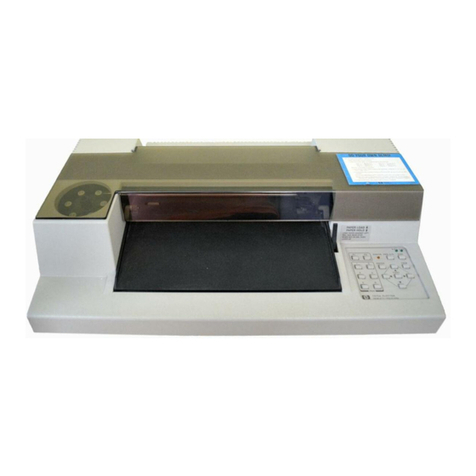
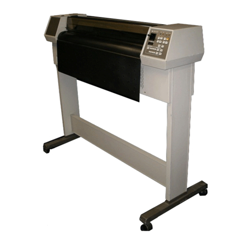
HP 7470A User manual

Other manuals for 7470A

3

Other HP Plotter manuals

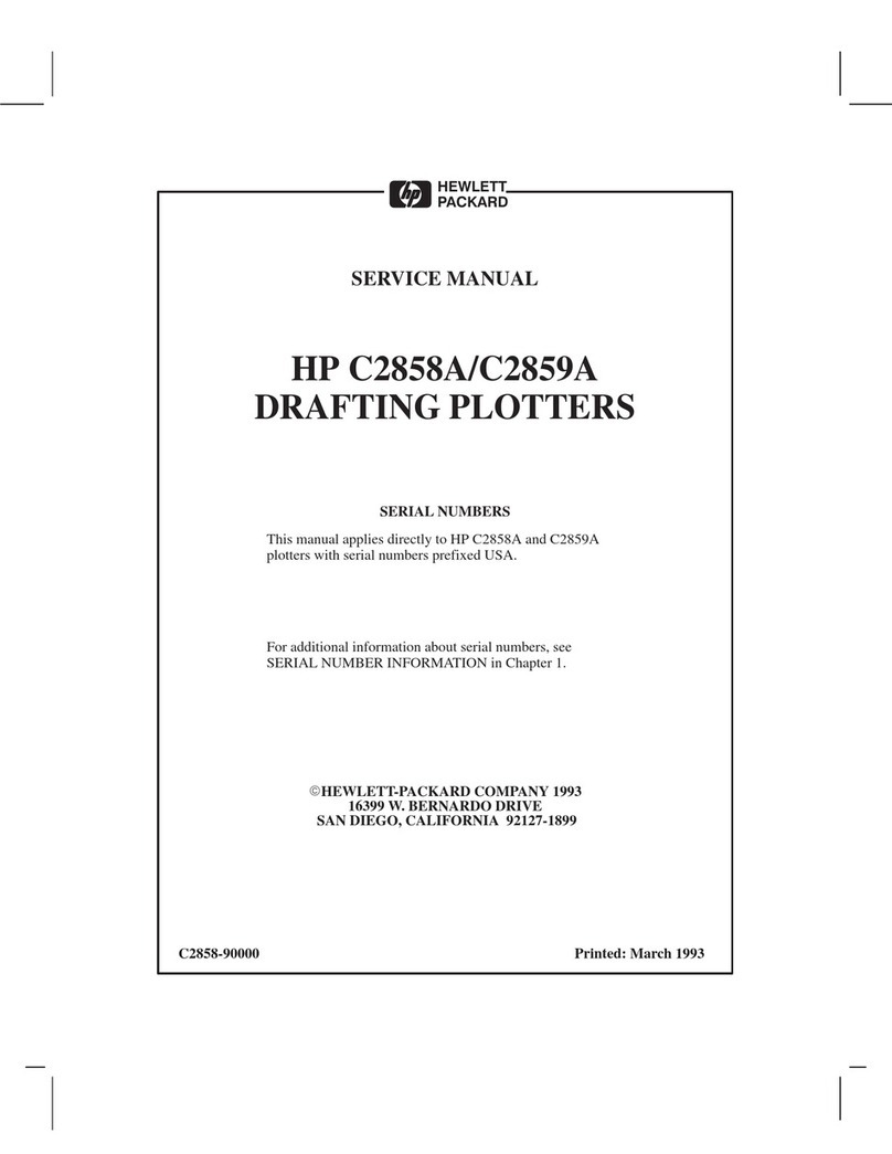
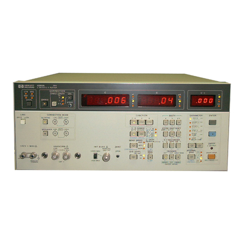
HP 7470A Owner's manual

HP

HP 7470A Owner's manual

HP 7475a User manual

HP

HP 7475a User manual

HP DesignJet 200 User manual

HP

HP DesignJet 200 User manual

HP DesignJet 700 User manual

HP

HP DesignJet 700 User manual

HP 7470A Owner's manual

HP

HP 7470A Owner's manual

HP DesignJet 650C C2858B User instructions

HP

HP DesignJet 650C C2858B User instructions

HP DesignJet 250C User manual

HP

HP DesignJet 250C User manual

HP C2858A User manual

HP

HP C2858A User manual

HP DesignJet 2500CP User manual

HP

HP DesignJet 2500CP User manual

HP DesignJet 350c Series User manual

HP

HP DesignJet 350c Series User manual

HP DesignJet 3500CP User manual

HP

HP DesignJet 3500CP User manual

HP Designjet 230 User manual

HP

HP Designjet 230 User manual

HP 4280A Operation manual

HP

HP 4280A Operation manual

HP Designjet T1200 series User manual

HP

HP Designjet T1200 series User manual

HP DesignJet 750c plus Series User manual

HP

HP DesignJet 750c plus Series User manual

HP C2858A User manual

HP

HP C2858A User manual

HP Designjet 330 User manual

HP

HP Designjet 330 User manual

HP 7470A User manual

HP

HP 7470A User manual

HP 7475a User manual

HP

HP 7475a User manual

HP DesignJet 700 User manual

HP

HP DesignJet 700 User manual

HP Designjet 230 User manual

HP

HP Designjet 230 User manual

HP 650c - DesignJet Color Inkjet Printer User manual

HP

HP 650c - DesignJet Color Inkjet Printer User manual

HP 7585B User manual

HP

HP 7585B User manual

HP CalcPad 200 User manual

HP

HP CalcPad 200 User manual

Popular Plotter manuals by other brands

MUTOH Kona 760 Service manual

MUTOH

MUTOH Kona 760 Service manual

Vulcan-Hart FC-500VC user manual

Vulcan-Hart

Vulcan-Hart FC-500VC user manual

Roland TrueVIS VG-640 Supplemental manual

Roland

Roland TrueVIS VG-640 Supplemental manual

MIMAKI CF2 Series Operation manual

MIMAKI

MIMAKI CF2 Series Operation manual

Roland VersaUv LEF - 12i troubleshooting guide

Roland

Roland VersaUv LEF - 12i troubleshooting guide

Roland VersaCamm SP-540V user manual

Roland

Roland VersaCamm SP-540V user manual

Seiko I Infotech LP-1020 user guide

Seiko I Infotech

Seiko I Infotech LP-1020 user guide

Ioline Summit Service manual

Ioline

Ioline Summit Service manual

Roland VersaUV LEF-200 Tutorial

Roland

Roland VersaUV LEF-200 Tutorial

ENCAD T-200 Service manual

ENCAD

ENCAD T-200 Service manual

GRAPHTEC CE6000-120AP user manual

GRAPHTEC

GRAPHTEC CE6000-120AP user manual

Furuno RP-17 Operator's manual

Furuno

Furuno RP-17 Operator's manual

MIMAKI CFL-605RT Operation manual

MIMAKI

MIMAKI CFL-605RT Operation manual

Skycut D Series user manual

Skycut

Skycut D Series user manual

Furuno GP-3500 installation manual

Furuno

Furuno GP-3500 installation manual

Great Computer JII-61 user manual

Great Computer

Great Computer JII-61 user manual

Tektronix 4662 user manual

Tektronix

Tektronix 4662 user manual

Vulcan-Hart FC-500VC Quick setup guide

Vulcan-Hart

Vulcan-Hart FC-500VC Quick setup guide

manuals.online logo
manuals.online logoBrands
  • About & Mission
  • Contact us
  • Privacy Policy
  • Terms and Conditions

Copyright 2025 Manuals.Online. All Rights Reserved.

,
J,/
m
HRWUTT
PACKARD
"
%
SERVICE
MANUAL
GRAPHICS
PLOTTER
SERIAL NUMBERS
This,manual applies directly to plotters
refix numben 2644V and
2517A.
withwria#
W
hanges described in Sec-
tion IV, this manual also applies to plot-
tenprefixed2308A, 2250A, and 2148A.
For additional important information
about serial numbers, see PLOTTERS
COVERED
BY
MANUAL in Section I.
Copyright
@
HEWLETT-PACKARD COMPANY 1982,1986
16399W. BERNARD0DRIVE, SAN DIEGO, CALIFORNIA 92127
I
MANUAL PART NO. 07470-90000 Printed: SEPTEMBER 1984
I
i
Revision
A:
October
198tj
...
"'-
Table of Contents
TABLE OF CONTENTS
Page Section
.
Page
.
GENERALINFORMATION
.............
1.1
.
Introduction
.......................
13
.
SpcScations
.....................
1.7
.
SafetyConsiderations
.............
1.9
.
Ddption
........................
1.13
.
heVoltage and Fuse
........................
Selection
1.17
.
GroundingRequirements
..........
1.19
.
Plottars Covered by Manual
........
1.24
.
Options
...........................
1.28
.
Accessonen Supplied
...............
1-30
.
Packagingfor Shipment
...........
Rear
Panel Switches (Option
001)
...........................
HP-IBInterface(Option 002)
.....
Rear PanelSwitches(Option
002)
...........................
HewlettPackard InterfaceLoop
(Option 003)
...................
Rear Panel US/A4 Switch (Option
003)
...........................
........................
Proceseor
Read
Only Memory
..............
.........
Random AccessMemory
............
GateArraysA and B
Motor Supply Voltage
Comparator
...................
............
Motor ServoSystems
............
Motor Current Sensor
Pen Down Circuit
................
...
Parta Removal and Replacement
Top
Case
........................
PaperDrive Motor Assembly
(Figure
55)
....................
.........
Pen Solenoid(Figure
55)
........
Pen Drive Motor and Belt
Pen Carriage. Pen Holder. and
Damper
.......................
Pen Stablw
......................
Pinch Rollers
....................
Printed
Circuit Assembly
........
Pinch RollerMechanism and
.............
Paper Drive Shaft
Power Module and
Transformer
...................
............
Power Module Wiring
RecommendedTest Equipment
.....
Troubleshooting
...................
Exchange
Printed
Circuit
Amembly
......................
Drive Motonr andPen
Solenoid
.......................
Troubleshooting Table
...........
Test A
...........................
Test B (SeeTable
55)
............
Diagrams
.......................
PERFORMANCETESTS
................
2.1
.
Introduction
.......................
2.3
.
Basic Operating Test
..............
2.5
.
Hewlett-Packard Graphics
Language
.......................
2.7
.
Test
Program
......................
REPLACEABLE PARTS
.................
3-1
.
Introduction
.......................
3.3
.
ExchangeAssemblies
..............
3-5
.
ReplaceableParts Liat
.............
3-7
.
OrderingInformation
..............
3-9
.
CodeLiat of Manufacturers
........
3-11
.
Designations and
...................
Abbreviations
....................
MANUAL
CHANGES
4-1
.
Introduction
.......................
...............
.
4-4
Serial
Preh
History
4.6.
Changes
...........................
4-7
.
Change
1
........................
4-10
.
Change 2
........................
4-12
.
Change3
........................
415
.
Change4
........................
SERVICE
................................
51
.
Introduction
.......................
.................
53
.
Circuit Description
57
.
RS-232-C/CCm V.24 Interface
(Option001)
...................
TABLES
Tge
Page
Table
.
Page
.
1.1
.
Specifications
.........................
1-1
3-3
.
1-2 LineVoltage Selection
.................
1-2
1.3
.
Power Cord Configuration
.............
13
3-4
.
14
.
AccessoriesSupplied
...................
1-6
2.1
.
7470A HP-GLInstruction Set
..........
2-2
35
.
31
.
Parta Liat. Main PCA. RS.232.C.
3.6
.
Option 001
...........................
3.2
32
Parta Liat, Main PCA. HP.IB
.
41
.
Option 002
...........................
3-5
Parta Liat. Main PCA. HP.IL,
Option 003
...........................
3-7
PartaList. Replaceable
....................
Mechanical Parta 3-10
..............
Manufacturers' Code List 3-12
ReferenceDesignations and
.......................
Abbreviations 3-13
History of
Serial
Refir
.............................
Changes 4-1
Revision
A:
October 1986
iii
Tableof Contanb
Model
7470A
TABLES
(Continued)
4-2
Parta
Lirt,
Main
PCA,
RS-2324.
Option001
...........................
4-3
.
Pam
Lirt,
Main
PCA
HP.IB.
Option 002
...........................
44
.
Parta
Lht,
Main
PC&
HP.IL,
Option
003
...........................
4-5
.
Parta
Lirt,
Main PC& RS-2324.
option 001
...........................
Pae Table
.
ILLUSTRATIONS
Parta
List,
Main
PC&
HP.IB.
...........................
Option 002
4-20
RS-232-C/CCm V.24 IntarfaceSial
bvls
...............................
5-1
Baud
Rate
%action
...................
5-2
..................
HP-IBInterface
Lines
5-3
RecommendedTeat Equipment
.........
5-13
Troublwhwting
.......................
5-15
Fie-
paoe
Fie-
Top CareRemoval
.....................
1-2
5-45
.
Line
VoltageSelection
.................
13
Power Cord Cdguntiona
............
13
5-6
.
Tat
Program
..........................
24 5-7
.
ParformanceVdcationPlot
..........
2-6
58
.
Exploded View
........................
3-11
5-9
.
SchematicDiagram.
RS-232-C.
5-10
.
Option 001
...........................
4-5
5-11
.
Schematic
Diagram.
HP.IB. 5-12
Option002
...........................
4-9
5-13
.
Schematic Diagram. HP.IL, 5-14
.
Option003
...........................
4-15
5-15
.
SchematicDiagnunr. Power Suppk
...
4-23
RS2324/CCTX' V.24 Interface 5-16
.
Circuih
.............................
5-2
HP-IL
Interface
Citr
...............
54
5-17
.
ServoSystamBlock Diagram
..........
5-45
.....................
TopCase Removal
5-6
5-18
.
Paper Drive
Motor
and Pm
Solenoid
.............................
Pen Drive
.............................
Pen Stablw
............................
Pinch
Rollem
..........................
............
ChauiaAuambly Removal
.......
Under Sideof
Chauir
Auembly
Power Module Ramoval
................
PowerModule
Wiring
..................
Schematic Diagram No-
.............
ANSI
Y3214LogicSymbol8
...........
SchematicDiagram. RS-2324. Option
001
..................................
Schematic
Diagram.
HP.IB.
Option
002
..................................
Schematic
Diagram
.
HP.1
L.
Option
.
.
.
003
..................................
SchematicDiagram, Pow= Suppliaa
....
Fievirion
A:
October 1986
.
-
Safety
Symbob
Genenl Definitionsof Safety Symbols
Used
On Equipment
International caution symbol (refer
to
manual): the product
will
be
marked with this symbol when it is necessary for the user torefer
to
the instruction manual in order
to
protect against damage tothe
instrument.
4
Indicatesdangerousvoltage (terminalsfed from the interior by
voltage exceeding
1000
volts must be so marked).
Protectiveconductor terminal. For protection against electrical
shock in case of
a
fault. Used with field wiring terminals
to
indi-
cate the terminal which must be connected to pound before
operatingequipment.
Low-noise or noiseless, clean pound (earth)
terminal.
Used for a
signal common,
as
well
as
providing protection against electrical
shock in case of a fault. Aterminal marked
with
this symbolmust
be
connected
to
ground in the manner described in the installation
(operating)manual, and before operating the equipment.
Frame or chassis terminal. Aconnection
to
the frame (chassis)of
lj7
OR
A
the equipmentwhich normally includes allexposed metal struc-
tures.
-
Alternatingcunent
-
000
Direct cuxrent
G
Alternatingor direct current
The WARNING sign denotesa hazard. It calls attention to
a
pro-
cedure, practice, or the like, which, if not correctly performed or
adhered
to,
could result in personal injury.
The CAUTION sign denotes a hazard. It calls attention to
an
op-
eratingprocedure, practice, or the like, which if not correctly
performed or adhered to, could result in damage
to
or destruction
of
part
or
all
of the product.
Revision
A:
October
1986
7470A
lNTROOUCTION
--
section
I
SECTION
I
GENERAL INFORMATlON
Table 1-1. Swcations
1.2.
Thb
dce
manual con- informationnecea-
sary
to
test and
service
the Hewlett-Packard Model
7470A Plotkr.
Thin
manual
is
divided
into
fivesections
aa
foilown:
1
-
General
Information
I1
-
PerformanceTests
III
-
Replaceable Parts
IV
-
ManualChanges
V
-Senrice
13. Information for interfacing and operating the
Model 7470A will
be
found in thefollowing:
Title
-
Interfacingand
Program-
.
ming Manual
OperatingManual
InterconnectionGuide
Programmer's Reference
HP
Psrt Number
14.
This
General Information section contains the
spdicationsand option andaccemoryinformation.
I
1-5.
SPECIFICATIONS
1
1-6.
Table 1-1lists the sptdicatiom for the Model
I
7470A. These spaQfications include the performance
standardsagainst which the plotter
is
tested.
1-7. SAFETY CONSIDERATIONS
1. Safetyinformation relevant
to
the
service
pmcc
dun
being
described
ia
provided in the appropriate
sections of this manual. The Model 7470A and this
manual should be reviewed for safety markings and
instructionsbefore senricework
is
begun.
1 DESCRIPTION
1-10. The Model 7470A accepta digital informationto
produce graphic plots on
X
11 in. or IS0 A4 (210
X
297 mm) paper or special transparency plastic. Dis-
posable pens
are
available in variousink colors.
1-11. The two-pen capability permits more than one
color to
be
used in a plot without the necessity of
stopping the plotter to change pens manually. Pens
are
automatically capped when in the pen stables. A
pen
that is in the pen carriage
will
be automatically
replaced in its stable when the PAPER LOADIHOLD
lever is moved to the LOAD position. Either pen may
MAXIMUM
PLO'ITING AREA
Y
axis:
190
mm
(7.5 in.)
X
axis:
273 mm (10.7 in.) metric
258
mm
(
10.2 in.) English
REPEATABIUTY
With the same pen: 0.1 mm (0.004
in.)
With a differentpen: 0.2
mm
(0.008
in.)
PENVELOCX'IY
Pen down: maximum,
38.1
cm/s (15in./s)
programmable,1
to
38
cm/s in
1cm/s increments
Pen up: 50.8 cm/s (20in./s)
ADDRESSABLE
STEP
SIZE
0.025 mm (0.00098in.)
ACCELERATION
Approximately2g
POWER
REQUIREMENTS
Source:
100,120,220,or 240
V-
-1096,
+5%
Frequency:
48
to
66
Hz
Consumption:
25
W
maximum
SIZE
Length: 432 mm (17in.)
Width:
343
mm
(
13.5
in.)
Height: 127
rnm
(5
in.)
WEIGHT
5.7
kg
(125Ib)
be selected by program control or by pressing the PEN
LEFT
(1)or PEN RIGHT (2)button. To replace a pen
in
its
stable, hold the ENTER button down while
pressing the appropriate pen select button.
1-12 Seven different
line
types
are
provided. Label-
ingcan
be
donein five character setsplua userdefined
characters (except in
HP-IL
Option 003). Text (label-
ing)
can
be
written
in
any direction, upright or slanted.
Character size
is
also
variable.
1-13.
LINEVOLTAGE AND FUSE SELECTION
To prevent damageto theplotter, make
sure the line voltageselectionand fuse
protection
is
correctbefore connecting
line power.
Revision A: October 1986
Section
I
Model
7470A
The line power cord and power outlet
must have a protective earth (ground)
contact.
1-14.
The
7470A
primary power circuit can be con-
figured to operate from any one of the following power
sources ata line frequency of
48
to
66
Hz,
single phase.
Maximum power used is
25
W.
1-15.
Line voltage selection is identified on the label
visible in the small receased window in the rear panel.
Applying line voltage of
220
Vor
240
V
to the plotter while the line voltage
selection is set for
100
V
or
120
V
operation may damage the plotter
circuits.
1-16.
The line voltage selection may be changed to
conform to the line voltage in a particular area Use
the following procedure.
F]
The followingprocedure should
be
per-
formed only by servicatrained person-
nel who
are
awareof theelectrical shock
hazards involved.
a.
Set the plotter LINE switch to OFF
(0)
and dis-
connect the line cord.
b. Remove the plotter top case by removing the
screws indicated in Figure
1-1.
Lift the rear of
the top case and the front will release. When
replacing, make sure the PAPER HOLD lever
extends through the case. and the tabs inside
the front of the top care
align
properly above
and below the bare plate.
11\1\1111"""
REMOVETHESE SCREWS
TO RELEASE
TOP
CASE
74704-2.1
Figure
1-1.
Top Case Removal
c. Line voltage selection
is
determined by the power
input connections to the transformer primary
windings. Table
1-2
lists the wire colors and
transformer contact connections for each line
voltage. Thetransformer pin numbers areiden-
tified on the power module molding. Figure
1-2
illustrates the connections for each voltage.
Changethe wire connections asrequired to con-
form to the desired linevoltage selection.
Make sure the line fuse is correct
accordingtoTable
1-3.
Thefuseholder
cap is the bayonet type. Press and
turn counterclockwise
to
remove,clock-
wise to lock.
d. Change the position of the line voltage label
block so that the voltage selected is right side
up. This block snaps in and out of the power
module molding.
Table
1-2.
Line Voltage Selection
*Wireidentification is by color code:
8
=CRY
928
=
WHT:RED/GRY
958
=
WHT:GRN/GRY
NOMINAL
LINE
VOLTAGE
100
V
120
V
220
V
240
V
TRANSFORMER PRIMARY CONNECTIONS*
PIN
1
8
8
8
8
PIN
2
928
NC
958
NC
PIN
3
958
928
NC
958
PIN
4
8
8
958
958
PIN
5
958
928
928
928
PIN
6
NC
958
8
8
PIN
7
928
958
928
928
7--
Model
7470A
--
Section
I
HP
Part
Number
8120-1369;
250
V,
10
A,
1
4
plug rating. For use
in
Australia, New
Zealand
OptionNo.
HP
Part
Number
8120-1351;
250
V,
13
A,
1
4
900
plug rating. For
me
in
United
Kingdom.
Cyprus,
Ni
Zimbabwe,Singapore.
0
0
NEMA b15P
9
NEMA
615P
SEV
1011
cT3
n
0
(=j
NOTE
AU
plugs
are
viewed
from
connectorend.
L
=
Lineor ActiveConductor
(also
called
"live" or "hot")
N
=
Neutral or Identified Conductor
E
=
Earth or
Safety
Ground
!.A-184
HP
Part
Number
8120-1689;
250
V,
10/16
A,
1
4
plug rating. For
use
in
East and
West
Europe, Egypt
-
HP
Part
Number
8120-1378;135
V,
15
&'.I
6
plug rating. For use
in
Canada, Japan,
Mexico,
Philippinen,
Taiwan,
Saudi
Arabia,
UL
approved
in
United
States.
HP
Part
Number
81204698;
250
V,
15
A,
1
4
plqgrating. For
use
in
Canada,
UL
approved
in
United
Statea
HP
Part
Number
8120-2104;
250
V,
10
A,
1
6
plug rating. For
use
in
Switzerland.
HP
Part
Number
8120-W,
250
V,
10
A,
1
4
plug rating. For
use
in
Denmark.
HP
Part
Number
81204211;
250
V,
10
A,
1
&
plug rating. For
use
in
India,
Republic of
South
Africa.
Figure
1-3.
Power Cord Configurations
Revision
A:
October
1986
1-5
Table
14.
Acceuoricrr
Supplied
OperatingManual
I I
DESCRIPTION
*Intarfacingand Pmgramming Manual
Interconnection Guide
I
1
I
Qm
1
Programnier's
Referam
Card
I I
*.Plotter paper,
8%
x
11
in.,
50
ah&
I
1
I
Package of
5
fiber
tippenr.
0.3
mm nib
width.
1
each
red,
blue, green. black. yellow
I1
HP
PART
NUMBER
I
*Supplied with Option
001
only.
*.Paper
size
A4
(210
x
297
mm)
HP
PartNo.
17802P
may
be
rupplid,based on the destination of the plotter.
1-32.
If
the original packaging material har been
re
c.
Urn a layer of shock-absorbingmaterial atleast
tained. pack the plotter in the same manner as it was
70
to
100
mm
(3
to
4
in.) thick around all side8

received. The following general instructionr should
be
of the plotter
to
provide
firm
cushioning and
used for packingwith commercially availablemateriala. preventmovementinsidethe container.
a. Wrap theplottar
in
heavy paper or plertic.
b. Ure a rtrong hippingcontain-.
d.
Seal
contain- securely.Mark contain-
FRAGILE
to
enrurecarefulhandling.
Revirion
A:
October
1986
Section
111
1
7470A
SECTION
Ill
REPLACEABLE
PARTS
&1.
INTRODUCTION
Table
3.3
=
Option
003
PCA
Table
3-4
=
Mechanical parts
3-2.
Thie section contains information for ordering
parts
for the HP Model
7470A
Plotter. Included are
3
ORDERING INFORMATION
lista
of electrical and mechanical parte and an illue-
tration of mechanical parts.
3-8.
To obtain replacement parts or aesembliee ad-
dress anorder or inquiry to the nearest Hewlett-Packard
3-3.
EXCHANGEASSEMBLIES
Salesand Support Office.Include the HP Part Number,
the check digit (listed under the heading "CD" in the
3-4.
Part numbers for aesembliee that are available parte list).the description. and thequantity required.
on an exchange basis are listed in theparts lists below
the new assembly number. These factory repaired and
3.9.
CODE LIST
OF
MANUFACTURERS
tested assemblies areavailable only on a tradein basis:
therefore. the defective assembly must be returned for
3-10.
Table
3.5
lists the fivedigit code numbers as-
credit. For this reason. aseemblieta required for spare simedto the manufacturers of pans in the Model
7470A
parts stock must be ordered by the new part number. Plotter. These code.numbers appear with the parts in
Tablee
3-1
through
3-4
as an aid for ordering replace
3-5.
REPLACEABLEPARTS LISTS
ment parts directly from the manufacturer.
3-6.
Electrical parts for the
7470A
are lieted in Tables
3-11.
DESIGNATIONSAND ABBREVIATIONS
3.1
through
3-3.
Table
3.4
is
a
list of mechanical parts
which are illustrated in Figure
3-1.
3-12.
Table
34
lista designations and abbreviationsueed
throughout this manual. Abbreviations in the parts
Table
3-1
=
Option
001
PCA lists are always capital letters. In other parts of the
manual both upper and lower case abbreviations are
Table
3.2
=
Option
002
PCA used.