HP Designjet 230 User manual


iiiCont nts
C4699Ć90000
Cont nts
Using this Manual ii..................................................
Saf ty Symbols x.....................................................
Applications 1Ć2...........................................................
Driv rs 1Ć2...............................................................
Graphic Languag s 1Ć2....................................................
D vic ĆControl Languag s 1Ć2..............................................
Int rfac s 1Ć3.............................................................
N twork Conn ctions 1Ć3..................................................
M mory 1Ć3..............................................................
Accuracy 1Ć3..............................................................
R solution 1Ć4............................................................
L gs 1Ć4..................................................................
RollĆf d 1Ć4..............................................................
Upgrading a D signJ t 330 1Ć4.............................................
M dia 1Ć4................................................................
Pow r R quir m nts 2Ć2...................................................
Choosing an Int rfac Cabl (mor Us r's Guid ) 2Ć2...........................
Choosing a Suitabl Plott r Environm nt (mor Us r's Guid ) 2Ć3...............
Environm ntal Sp cifications 2Ć3........................................
Plott r Dim nsions and W ight 2Ć3......................................

iv Contents C4699Ć90000
Unpacking and Assembling the Plotter 3Ć2...................................
Inspecting the Plotter for Damage 3Ć4.......................................
Repacking the Plotter 3Ć4...............................................
Assembling the Legs (Optional) 3Ć5.........................................
Assembling the RollĆFeed Assembly (Optional) 3Ć8............................
Installing the Plotter (more User's Guide) 3Ć12..................................
Using the Plotter (more Quick Reference Guide) 3Ć12..............................
DesignJet 230 Front Panel 3Ć12..........................................
DesignJet 250C Front Panel 3Ć12.........................................
DesignJet 330 Front Panel 3Ć13..........................................
DesignJet 350C Front Panel 3Ć13.........................................
hirdĆParty Inks and OffĆAxis Ink Systems 3Ć14...........................
Configuring the Plotter 3Ć14.................................................
Verifying Plotter Operation 3Ć14.............................................
PowerĆOn SelfĆ ests 3Ć14................................................
Demonstration Plot 3Ć14.................................................
Example of Setup Sheet (DesignJet 250C) 3Ć15................................
Example of Setup Sheet (DesignJet 350C) 3Ć16................................
Moisture on Plotter 4Ć2....................................................
Level of Plotter Usage 4Ć2..................................................
Friction on Slider Rod 4Ć2..................................................
Noisy Carriage Wheel 4Ć2..................................................
Ink Spilling 4Ć3...........................................................
Belt Swelling 4Ć3..........................................................
Cleaning the RollĆfeed Assembly 4Ć3........................................
Cleaning the Plotter 4Ć4...................................................
General Cleaning 4Ć4...................................................
Cleaning the Drive Roller 4Ć4...........................................

vContents
C4699Ć90000
(more HP DesignJet 200/220 ervice Manual)
Introduction 5Ć2..........................................................
Loading heet Media 5Ć2...................................................
Loading Roll Media on the DesignJet 330 and 350C 5Ć4.......................
Roll Media 5Ć5............................................................
Removing tatic Charge from the Media 5Ć5.................................
Gripping the Media 5Ć5....................................................
PinchĆArm ensor 5Ć5..................................................
Providing a Force on Top of the Media 5Ć6...................................
Bail 5Ć6...............................................................
BailĆLift Mechanism 5Ć6................................................
Moving the Carriage 5Ć6...................................................
CarriageĆDrive Mechanics 5Ć6...........................................
Motor, Belt and Pulley 5Ć6...........................................
Carriage Guidance 5Ć6..............................................
Positional Feedback 5Ć6.............................................
Detecting the Lines and Media Edges 5Ć7....................................
Line ensor 5Ć7........................................................
Providing Ink 5Ć7.........................................................
Print Cartridges 5Ć7....................................................
Distance between Carriage and Media 5Ć7.............................
Producing an Image 5Ć8....................................................
PrintĆMode Characteristics 5Ć8..........................................
ervicing the Cartridges 5Ć11................................................
ervice tation 5Ć11.....................................................
pittoon 5Ć11...........................................................
Primer 5Ć11............................................................
Plotter Architecture 5Ć12....................................................
Electronics Module 5Ć13....................................................
MainĆPCA Connections 5Ć13.............................................
ensors 5Ć13............................................................
ROM 5Ć14..............................................................
RAM 5Ć14..............................................................
EEROM 5Ć14...........................................................
Input/Output Interfaces 5Ć14.............................................
BiĆTronics 5Ć14......................................................
R Ć232ĆC 5Ć14.......................................................
Power upply 5Ć15......................................................
Water Condensation 5Ć15................................................
Memory Usage 5Ć15........................................................
Plot Orientation 5Ć15....................................................
Raster Image Processor 5Ć15.............................................
Carriage PCA 5Ć16.........................................................
Front Panel PCA 5Ć16......................................................

vi Contents C4699Ć90000
Safety Precautions 6Ć2.....................................................
ESD Precautions 6Ć2......................................................
Reassembly 6Ć2...........................................................
Require Tools 6Ć3........................................................
Repair Proce ures 6Ć4.....................................................
Installing a RAM or ROM SIMM 6Ć4.....................................
Removing the Bail 6Ć5..................................................
Removing the Cartri ge Caps an Wiper Bla es 6Ć6.......................
Removing the Top Cover 6Ć7............................................
Removing the RollĆfee Assembly 6Ć8....................................
Removing the Left En ĆCover 6Ć9.......................................
Removing the Right En ĆCover 6Ć10......................................
Disconnecting the FrontĆPanel Assembly 6Ć12..............................
Removing the Electronics Mo ule 6Ć13....................................
Removing the Me iaĆSensor Assembly 6Ć15................................
Replacing the Me iaĆSensor Assembly 6Ć16................................
Removing the Enco er Strip 6Ć17.........................................
Reinstalling the Enco er Strip 6Ć19.......................................
Removing the Right Bracket 6Ć21.........................................
Removing the Carriage Motor 6Ć21........................................
Removing the Spittoon 6Ć23..............................................
Removing the Spittoon 6Ć24..............................................
Removing the PinchĆArm Sensor 6Ć25.....................................
Removing the DriveĆRoller Gear 6Ć25.....................................
Removing the Me ia Motor 6Ć26..........................................
Removing the PinchĆArmĆLever Linkage 6Ć27..............................
Removing the Primer 6Ć27...............................................
Removing the Service Station 6Ć28........................................
Removing the BailĆLift Mechanism 6Ć29...................................
Removing the EngagingĆLever Support 6Ć31...............................
Removing the Over rive Roller 6Ć32......................................
Removing the Back Cover 6Ć33...........................................
Removing the Trailing Cable 6Ć34........................................
Repositioning the Trailing Cable 6Ć35.....................................
Removing the TrailingĆCable Gui e 6Ć36..................................
Removing the Cartri ge Carriage 6Ć37....................................
Removing the Drive Belt 6Ć39............................................
Removing the DriveĆBelt Pulley 6Ć40......................................
Removing the Drive Roller 6Ć41..........................................
Reinstalling the Drive Roller 6Ć42........................................
Removing the PinchĆArm Lift Mechanism 6Ć44.............................
Reinstalling the PinchĆArm Lift Mechanism 6Ć45...........................
Removing the Over rive Enclosure 6Ć46...................................
Reinstalling the Over rive Enclosure 6Ć47.................................
Removing the Entry Platen 6Ć48..........................................
Reinstalling the Entry Platen 6Ć49........................................
viiContents
C4699Ć90000
When to Calibrate the lotter 7Ć2...........................................
Black Cartridge Alignment (See User's Guide, chapter 1) 7Ć2......................
Color Cartridge Test (See User's Guide, chapter 3) 7Ć2............................
Service Modes 7Ć3.........................................................
Entering Service Mode 1 7Ć3............................................
Entering Service Mode 2 7Ć4............................................
Stopping a Test 7Ć4.....................................................
FrontĆ anel Keys in Service Mode 7Ć5....................................
ressing Two Keys Together 7Ć5.........................................
Software Diagnostics and Hardware Tools 7Ć5.............................
ServiceĆMode 1 (DesignJet 230) 7Ć6......................................
ServiceĆMode 2 (DesignJet 250C) 7Ć6.....................................
ServiceĆMode 1 (DesignJet 330) 7Ć7......................................
ServiceĆMode 2 (DesignJet 350C) 7Ć7.....................................
Accuracy Calibrations 7Ć8..................................................
Adjusting the CarriageĆtoĆMedia Distance 7Ć11................................
owerĆOn 8Ć2.............................................................
Self Test and Initialization 8Ć2..........................................
What You Should See and Hear 8Ć3......................................
FrontĆ anel LEDs 8Ć5.....................................................
Error Codes for the DesignJet 230 and 250C lotters 8Ć6......................
No LEDs On 8Ć6.......................................................
LEDs On (Error Off) 8Ć6................................................
LEDs Flashing 8Ć7.....................................................
Error LED On 8Ć9.....................................................
Error Codes for the DesignJet 330 and 350C lotters 8Ć13......................
No LEDs On 8Ć13.......................................................
LEDs On (Error Off) 8Ć13................................................
LEDs On or Flashing 8Ć13...............................................
LEDs Flashing 8Ć14.....................................................
Error LED On 8Ć15.....................................................

System Errors for the DesignJet 230 and 250C lotters 8Ć19....................
System Errors for the DesignJet 330 and 350C lotters 8Ć23....................
EEROM Errors 8Ć27........................................................
EEROM Model ID Configuration rocedure for the DesignJet 330 and 350C 8Ć28.....
Troubleshooting Tips 8Ć30..................................................
Service Tests 8Ć35..........................................................
Which Service Test to erform 8Ć35.......................................
Viewing Test Output on an H almtop C 8Ć36...........................
Bail Cycle Test 8Ć37.....................................................
Bench Run 8Ć38.........................................................

CarriageĆAxis Test 8Ć38..................................................

viii Contents C4699Ć90000
Carriage Test for the DesignJet 230 and 250C 8Ć39.........................
Carriage Test for the DesignJet 330 and 350C 8Ć40.........................
Electrical Test 8Ć41......................................................
FrontĆPanel Test 8Ć42...................................................
Input/Output Test for the DesignJet 230/250C Only 8Ć43....................
MediaĆAxis Test 8Ć44....................................................
Modular Test 8Ć45.......................................................
PrintĆQuality Plot 8Ć46..................................................
ensors Test for the DesignJet 230 and 250C 8Ć47..........................
ensors Test for the DesignJet 330 and 350C 8Ć48..........................
ervice Configuration Plot for the DesignJet 230 and 250C 8Ć49.............
ervice Configuration Plot for the DesignJet 330 and 350C 8Ć50.............
Printing the ervice Configuration Plot 8Ć51...............................
ervice Monitor (Data Display) 8Ć52......................................
ervo/Encoder Test 8Ć53.................................................
Clearing the EEROM for the DesignJet 230 and 250C 8Ć54.....................
Clearing the EEROM for the DesignJet 330 and 350C 8Ć55.....................
PrintĆQuality Troubleshooting 8Ć56..........................................
PrintĆQuality Plot 8Ć56..................................................
Banding 8Ć57...........................................................
Uneven Fill Density 8Ć58................................................
Lightfastness 8Ć58......................................................
pray 8Ć58.............................................................
VerticalĆLine traightness (VL ) 8Ć59.....................................
Ink mearing 8Ć60......................................................
Hue Changes 8Ć60.......................................................
tarwheel Marks 8Ć60...................................................
Misaligned Colors 8Ć61..................................................
Bleeding, Blooming and Wicking 8Ć61.....................................

ixContents
C4699Ć90000
Introduction 9Ć2..........................................................
SerialĆNumber Format 9Ć2.................................................
Firmware Revision Level 9Ć3...............................................
Obtaining Service Notes with Graphics 9Ć4..................................
From a PC 9Ć4.........................................................
From a NIX Workstation 9Ć4..........................................
Problem Reading the Setup Sheet 9Ć5.......................................
Exchange Assemblies 10Ć2..................................................
Replacement Parts 10Ć3.....................................................
Part Lists and ExplodedĆView Diagrams 10Ć4..................................
Legs 10Ć4...............................................................
Top and Back Covers, Electronics, Trailing Cable 10Ć6......................
End Covers 10Ć8........................................................
CarriageĆAxis (Left End) 10Ć10............................................
CarriageĆAxis (Right End) 10Ć12...........................................
Service Station, Primer, Spittoon 10Ć14.....................................
Media Entry Path 10Ć16..................................................
Bail and Overdrive 10Ć18..................................................
PinchĆArm Assembly 10Ć22...............................................
RollĆFeed Assembly 10Ć24.................................................
Accessories 10Ć26........................................................
Interface Cables 10Ć29....................................................
HewlettĆPackard support services in the nited States 11Ć2....................
HewlettĆPackard support services in Europe 11Ć4..............................
HewlettĆPackard support services in AsiaĆPacific 11Ć8..........................

International caution symbol (refer to manual): the product is
marked with this symbol when it is necessary for the user to refer
to the instruction manual in order to protect themselves and the
instrument against damage.
Indicates dangerous voltage (terminals fed from the interior by
voltage exceeding 1000 volts must also be marked).
Protective conductor terminal. For protection against electrical
shock in case of a fault. Used with field wiring terminals to
indicate the terminal that must be connected to ground before
operating equipment.
Low-noise or noiseless, clean ground (earth) terminal. Used for a
signal common, as well as providing protection against electrical
shock in case of a fault. A terminal marked with this symbol must
be connected to ground in the manner described in the installation
(operating) manual, and before operating the equipment.
Frame or chassis terminal. A connection to the frame (chassis) of
the equipment, which normally includes all exposed metal.
Alternating current
Direct current
Alternating or direct current
The WARNING sign denotes a hazard. It calls attention to a
procedure, practice, or the like, which, if not correctly performed
or adhered to, could result in personal injury.
The CAUTION sign denotes a hazard. It calls attention to an
operating procedure, practice, or the like, which, if not correctly
performed or adhered to, could result in damage to or destruction
of part or all of the product.
Take care not to cut yourself on the encoder strip inside the plotter.


1Ć2 Product Information C4699Ć90000
Description
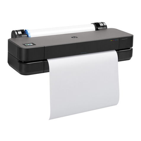
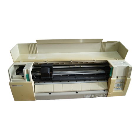
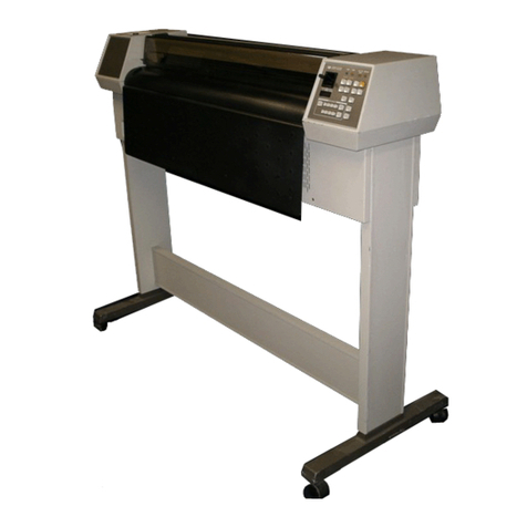
HP DesignJet 230 and 330 (monochrome) and HP DesignJet 250C and 350C (color) plotters
are largeĆformat, inkĆjet plotters that print output from software applications, on paper and
other media.
he plotters produce largeĆformat plots of high resolution and quality for the following
sectors:
DComputerĆaided design (CAD)
DComputerĆaided manufacturing (CAM)
DMapping
DMechanical and architectural drawing
DGeneral drafting
Software drivers for the following applications are supplied with the plotters:
DAutoCAD for DOS
DAutoCAD for Windows
DMicroSoft Windows Applications
(Other application software 'User's Guide, chapter 1.)
he plotters accept drawing data in the following graphic languages:
DHewlettĆPackard Graphics Language (HPĆGL), a vector language
DHPĆGL/2, an enhanced version of HPĆGL
DHewlettĆPackard Raster ransfer Language (HPĆR L), a raster language
When receiving HPĆGL/2 data, the plotters can recognize and output the KanaĆ8, Kanji, and
Roman character sets.
he plotters support the following languages, enabling the user to read certain plotter
settings from the computer:
DPrinter Job Language (PJL)
DPrinter Management Language (PML)

1Ć3 Product InformationC4699Ć90000
The plotters operate with a variety of computer systems through either the serial, RSĆ232ĆC
port or the parallel, BiĆTronics, extendedĆcapa ility port (ECP).
An autoswitching feature ena les the plotter to detect from which interface it is receiving
data, so you can send data through either interface without having to change the plotter
settings. (More on interfaces 'chapter 5, wInput/Output Interfaces.)
You can connect the plotters to a network through an optional HP JetDirect EX or
HP JetDirect EX Plus3 external print server. The range of network operating systems that
are supported are as follows:
Local Area Network Network Operating System Computer Operating System
Ethernet Novell Netware DOS, Windows
LAN Manager DOS, Windows
TCP/IP HP-UX, Sun OS, Solaris
TCP/IP IBM AIX
EtherTalk Macintosh, Apple Products
Token Ring Novell Netware DOS, Windows
LAN Manager DOS, Windows
TCP/IP HP-UX, Sun OS, Solaris, IBM AIX
The print server includes a network autoswitching feature and can detect from which
network it is receiving data. This ena les you to send data through different networks
without having to change the interface settings.
The plotters have a standard 4 mega ytes of onĆ oard random access memory (RAM). They
also have one RAMĆexpansion socket, which can hold an optional 4Ć, 8Ć, 16Ć or 32Ćmega yte,
single inĆline memory module (SIMM). The maximum RAM is 36 MB.
The accuracy of the plotters in drawing a vector is0.38 mm (0.015 in) or 0.2% of the
specified vector length, whichever is greater, at 23 _C (73 _F) at 50Ć60% relative humidity, on
HP Inkjet 0.012Ćcm (0.0048Ćinch) polyester film.

1Ć4 Product Inform tion C4699Ć90000
The resolution of the plotter output is me sured in dots per inch (dpi). The plotter
resolutions for different plotĆqu lity settings re s follows (see lso 'ch pter 5):
Print Quality Monochrome Plotting Color Plotting
Fast 300 x 300 dpi 300 x 300 dpi
Normal Addressable 600 x 600 dpi 300 x 300 dpi
Best Addressable 600 x 600 dpi 300 x 300 dpi
The plotter legs re option l. The E/A0Ćsize legs include medi diverter to prevent l rge
medi sizes from hitting the ground. The D/A1Ćsize legs h ve no medi diverter.
The rollĆfeed ssembly nd legs re option l. The E/A0Ćsize legs include medi diverter to
prevent l rge medi sizes from hitting the ground. The D/A1Ćsize legs h ve no medi
diverter. For ddition l inform tion on the rollĆfeed ssembly 'ch pter 5.
Users c n order n upgr de kit to upgr de DesignJet 330 to Designjet 350C. The kit c n
be inst lled by the user. For ddition l inform tion 'User's Guide, ch pter 6.
(See lso 'HP Medi Reference Guide)
Monochrome Plotting Color Plotting
Plain paper and plotter paper HP special inkjet paper
Plain vellum (HP preferred) or equivalent non-HP media
Plain translucent paper (HP preferred)
HP single-matte polyester film
For ddition l medi types v il ble 'User's Guide, ch pter 2, wChoosing media.


10Ć2 Par s and Diagrams C4699Ć90000
Exchange Assemblies
Exchange assemblies are fac oryĆrepaired and es ed assemblies ha you can order; hey are
lis ed in he following able. Exchange assemblies are available only on a radeĆin basis;
herefore, you mus re urn he defec ive assemblies for credi .
Exchange Assemblies
HP Part Number Qty Description
C3190-60139 1 Electronics Module
C4699-60039 1 Electronics Module

Other manuals for Designjet 230
2
This manual suits for next models
3
Table of contents
Other HP Plotter manuals

HP
HP C2858A User manual

HP
HP DesignJet 750c plus Series User manual

HP
HP DesignJet 2500CP User manual

HP
HP 650c - DesignJet Color Inkjet Printer User manual

HP
HP Designjet T1200 series User manual

HP
HP DesignJet 3500CP User manual

HP
HP C2858A User manual

HP
HP DesignJet Z6610 60 User manual

HP
HP 7475a User manual

HP
HP DesignJet 650C C2858B User instructions