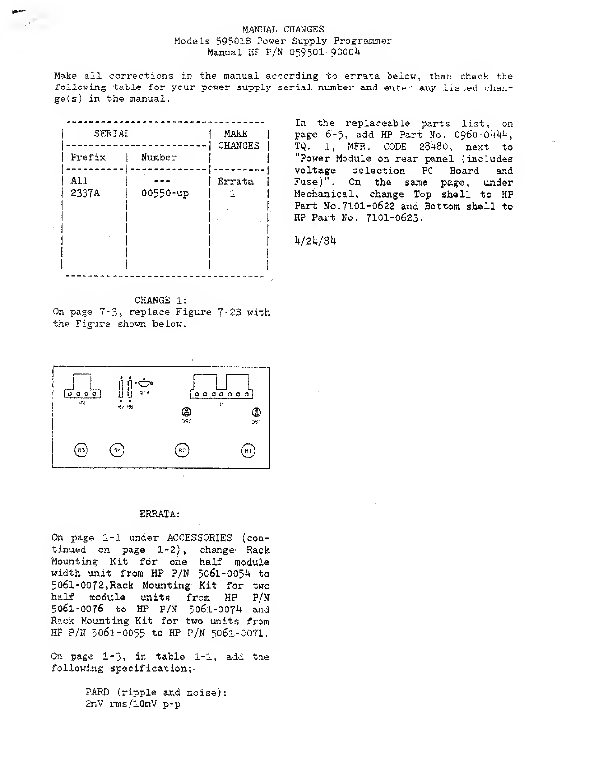
HP 59501B Service manual

OPERATING
AND
SERVICE
MANUAL
FOR
SERIALS
2308A-00101
AND
ABOVE
*For
Serials
above
2308A-00101
a
change
page
may
be
included.
HP
Part
No.
59501-90004
Manual
Microfiche
No.
59501-90005
Printed:
April
1983

MANUAL
CHANGES
Models
59501B
Power
Supply
Programmer
Manual
HP
P/N
059501-9000L
Make
all
corrections
in
the
manual
according
to
errata
below,
then
check
the
following
table
for
your
power
supply
serial
number
and
enter
any
listed
chan¬
ge
(s)
in
the
manual.
In
the
replaceable
parts
list,
on
page
6
-
5
,
add
HP
Part
No.
096Q~04hh,
TQ.
1,
MFR.
CODE
28U80,
next
to
"Power
Module
on
rear
panel
(includes
voltage
selection
PC
Board
and
Fuse)".
On
the
same
page,
under
Mechanical,
change
Top
shell
to
HP
Part
No.7101-0622
and
Bottom
shell
to
HP
Part
No.
7101-0623.
U/24/8U
CHANGE
1:
On
page
7~3,
replace
Figure
7-2B
with
the
Figure
shown
below.
ERRATA:
On
page
1-1
under
ACCESSORIES
(con¬
tinued
on
page
1-2),
change
Rack
Mounting
Kit
for
one
half
module
width
unit
from
HP
P/N
5061-0054
to
5061-0072>Back
Mounting
Kit
for
two
half
module
units
from
HP
P/N
5061-0076
to
HP
P/N
5061-007U
and
Rack
Mounting
Kit
for
two
units
from
HP
P/N
5061-0055
to
HP
P/N
5061-0071.
On
page
1.-3,
in
table
1-1,
add
the
following
specification;-.
PARD
(ripple
and
noise):
2mV
rms/10mV
p-p

SECTION
I
GENERAL
INFORMATION
1-1
INTRODUCTION
1-2
This
instruction
manual
contains
operating
and
service
instructions
for
the
HP-IB
Isolated
D/A
Power
Supply
Programmer
Model
59501B,.
Installation
instructions
and
sample
programs
are
also
provided.
The
59501B
allows
HP
power
supplies
to
be
digitally
controlled
via
the
Hewlett-Packard
interface
Bus
(HP-IB)
from
a
calculator,
computer,
or
other
controller.
The
digital
format
is
bit
parallel,
byte
serial,
ASCII
coded
format.
The
59501B
can
also
be
used
on
the
HP-IB
as
a
digitally
programmable
low
level
dc
signal
source.
Since
the
59501
B
!
can
be
controlled
(programmed)
by
various
control
devices
such
as
HP
9800
desk-top
computers,
hereafter
in
this
manual,
the
controlling
device
will
be
referred
to
as
the
"con¬
troller”,
except
when
specific
programming
examples
are
provided.
1-3
DESCRIPTION
1-4
The
59501B'.
is
basically
a
digital-to-analog
(D/A)
converter
that
provides
an
output
voltage
in
response
to
digital
data
received
on
the
HP-IB.
Two
programmable
output
ranges
(IV
and
10V)
are
available.
In
addition,
a
switch
on
the
rear
panel
allows
selecting
either
a
unipolar
or
bipolar
output
mode.
The
unipolar
mode
provides
a
0
to
,999V
or
a
0
to
9.99V
output
range
and
the
bipolar
mode
provides
a
—IV
to
+0.998V
or
a
—10V
to
+9.98V
output
range.
The
59501
B's
output
can
be
used
as
a
programming
voltage
for
controlling
a
wide
range
of
dc
voltages
and
currents
from
HP
power
supplies
or
as
a
source
voltage
for
testing
electronic
components
such
as
integrated
circuit
packages
(IC's).
1-5
Isolators
within
the
59501B
protect
other
instru¬
mentation
on
the
HP-IB
from
damage
that
could
be
caused
by
power
supply
outputs.
Also,
an
internal
circuit
ensures
that
the
output
is
held
near
zero
until
programmed
data
is
received.
Power
supply
programming
is
accomplished
through
use
of
the
59501
B's
programmable
output
voltage
and
its
front
panel
adjustments.
By
making
the
appropriate
connections
between
the
59501
B's
rear
terminals
and
the
programming
terminals
on
the
supply,
the
output
voltage
(or
current,
if
available)
of
the
power
supply
can
be
programmed
from
zero
to
its
full
rated
output.
The
59501
B's
front
panel
adjustments
provide
fast
and
easy
cali¬
bration
of
power
supply
outputs.
The
ZERO
ADJUST
enables
the
user
to
correct
for
small
offsets
in
power
supply
response
to
programmed
inputs.
The
POWER
SUPPLY
FULL
SCALE
ADJUSTMENT
(COARSE
and
FINE)
allows
the
user
to
set
the
maximum
output
desired
from
the
power
supply
when
the
59501B
is
programmed
touts
maximum
output.
This
method
of
programming
is
called
voltage
programming
with
gain.
Power
supply
program¬
ming
is
described
in
greater
detail
in
Section
III.
1-6
Programming
the
59501B
is
accomplished
through
the
transmission
of
four
consecutive
digits
(four
ASCII
characters).
The
first
digit
specifies
output
range
and
the
next
three
digits
specify
the
magnitude
within
the
selected
range.
The
high/low
range
capability
provides
a
ten
to
one
improvement
in
resolution.
Internal
conversion
circuitry
enables
the
59501B
to
produce
its
maximum
output
voltage
in
approximately
250^sec
from
the
time
the
digital
data
is
received.
Output
current
up
to
10
milliamps
is
available
and
is
automatically
limited
to
protect
the
59501B
and
the
user
equipment.
1-7
HP-iB
CAPABILITIES
1-8
The
59501B
has'listener"
and
"acceptor
hand¬
shake”
HP-IB
functional
capabilities.
The
LISTENING
indicator
on
the
front
panel
provides
a
convenient
means
of
monitoring
the
59501
B's
operating
status.
The
59501B
does
not
have:
controller,
talker,
source
handshake,
service
request,
device
trigger,
extended
listener,
extended
talker,
parallel
poll,
and
remote/local
HP-IB
functional
capabilities.
All
HP-IB
functional
capabilities
are
described
in
IEEE
Standard
488-1975.
1-9
SPECIFICATIONS
1-10
Detailed
specifications
for
the
59501B
are
given
in
Table
1-1.
1-11
ACCESSORIES
1-12
The
System-11
cabinet
accessories
listed
below
may
be
ordered
with
the
59501B
unit
or
separately
from
your
local
Hewlett-Packard
field
sales
office
(refer
to
list
at
rear
of
manual
for
addresses).
All
accessories
applicable
to
System-11
modular
cabinets
are
fully
described
and
illustrated
in
the
Hewlett-Packard
Electronic
Instruments
and
Systems
catalog.
1-1

H
P
Part
No.
5061-0088
5061-0094
1460-1345
5061-0054
5061-0076
5061-0055
5061-0096
5061-2021
5061-2022
1494-0015
Description
Two
front
handles
that
attach
to
each
side
of
3
1
/2"
high
cabinets.
Kit
of
lock
link
hardware
for
joining
together
cabinets
of
equal
depth.
Units
can
be
joined
side-by-side
or
vertically.
This
kit
is
required
whenever
two
(or
more)
sub-module
units
are
to
be
rack
mounted
side-by-side.
Tilt
stand
snaps
into
standard
foot
supplied
with
instrument
-
must
be
used
in
pairs.
Rack
mounting
kit
for
one
half
module
width
unit,
3
1/2-inches
high.
Includes
one
rack
flange
(ear)
and
one
half
module
width
extention
panel
(adapter).
Rack
mounting
kit
for
two
half
module
units,
3
1/2"
high.
Kit
includes
two
rack
flanges
(ears).
Also,
lock-together
kit
(5061-0094)
is
required
for
joining
the
two
units
together.
The
cabinets
must
also
be
of
equal
depth.
Rack
mounting
kit
for
two
units
(one
half
module
width
and
one
quarter
module
width).
Kit
includes
one
rack
flange
and
one
quarter
width
extension
adapter.
Lock-together
kit
(5061-0094)
is
required
for
joining
the
two
units.
Support
shelf
for
mounting
one
or
more
3
1
1
2
"
high
units
which
are
half
module
or
quarter
module
width.
Cabinet
depths
need
not
be
equal.
Front
filler
panel
(one
quarter
module
width)
for
3
1/2”
high
support
shelf.
Front
filler
panel
(one
half
module
width)
for
3
1/2"
high
support
shelf.
Slide
kit
for
support
shelves
mounted
in
HP
rack
enclosures.
1-13
INSTRUMENT
AND
MANUAL
IDENTIFICATION
1-14
Hewlett-Packard
instruments
are
identified
by
a
two
part
serial
number.
The
first
part
is
the
serial
number
prefix,
a
number-letter
combination
that
denotes
the
date
of
a
significant
design
change
and
the
country
of
manufac¬
ture.
The
first
two
digits
indicate
the
year
(10
=
1970,
11
=
1971,
etc.),
the
second
two
digits
indicate
the
week,
and
the
letter
A
designates
the
U.
S.
A.
as
the
country
of
manufacture.
The
second
part
is
the
instrument
serial
number;
a
different
sequential
number
is
assigned
to
each
instrument,
starting
with
00101.
1-15
If
the
serial
number
on
your
instrument
does
not
agree
with
those
on
the
title
page
of
the
manual,
Change
Sheets
supplied
with
the
manual
of
Manual
Backdating
Changes
define
the
difference
between
your
instrument
and
the
instrument
described
by
this
manual.
1-16
ORDERING
ADDSTIONALMANUALS
1
-17
One
manual
is
shipped
with
each
instrument.
Additional
manuals
may
be
purchased
from
your
local
Hewlett-Packard
field
office
(see
the
list
at
the
rear
of
this
manual
for
addresses).
Specify
the
model
number,
serial
number
prefix,
and
the
HP
Part
Number
provided
on
the
title
page.
1-19
In
addition
to
this
manual,
the
unit
is
shipped
with
Pro¬
gramming
Note
59501A/HP85-1
(HP
Part
No.
59501-90003)'.
This
note
also
applies
to
the
59501B
in
all
respects
and
pro¬
vides
programming
examples
for
use
with
the
HP85
or
other
BASIC
language
controllers,
as
well
as
CV/CC
Programming
Connections
between
the
59501A
and
various
HP
Power
Sup¬
plies.
This
information
supplements
the
programming
examples
for
the
9825
given
in
Section
III
of
this
manual.
1-2

Table
1-1.
Specifications,
Model
59501A
D/A
CONVERTER
DC
Output
Voitage:
Programmable
in
high
or
low
ranges
within
the
voltage
limits
shown
below.
Output
mode
is
unipolar
or
bipolar
and
is
selectable
via
rear
panel
switch.
High
Low
Unipolar
0
to
9.99
Volts
0
to
+.999
Volts
Bipolar
-10
to
+9.98
Volts
-1
to
+.998
Volts
DC
Output
Current:
10mA
Resolution:
High
Low
Unipolar
10mV
1m
V
Bipolar
20m
V
2m
V
Accuracy;
Specified
at
23°
C±
5°C
High
Low
Unipolar
.1%+
5m
V
.1%+
ImV
Bipolar
.1%+
10mV
.1%+
2m
V
*
Stability:
Change
in
output
over
8
hour
interval
under
constant
line,
load,
and
ambient
following
a
30
minute
warm-up.
H
igh
Low
Unipolar
.04%
+
.5mV
.04%
+
,1mV
Bipolar
.04%
+
1
m
V
.04%
+
.2mV
Temperature
Coefficient:
High
Low
Unipolar
.01%/°C
+
.5mV/°C
.
01
%/°C
+
.1
mV/°C
Bipolar
.01%/°C
+
.5mV/°C
.01%/°C
+
,1mV/°C
Zero
Adjust:
Plus
or
minus
250
millivolts.
D/A
Full
Scale
Adjust:
Plus
or
minus
5%.
Programming
Speed:
The
time
required
for
output
to
go
from
zero
to
99%
of
programmed
output
change
is
250/tsec
(measured
with
resistive
load
connected
to
output
terminals).
*
Stability
is
included
in
accuracy
specification
measure¬
ments
over
the
temperature
range
indicated.
POWER
SUPPLY
PROGRAMMING
Programming
Network
Specifications:
In
the
following
spec-
-
ifications,
M
represents
the
calibrated
full
scale
value
of
the
supply
being
programmed
and
P
represents
the
actual
pro¬
grammed
output.
Note
that
the
full
scale
value
(M)
can
be
any
value
within
the
supply's
output
range
and
is
calibrated
with
the
59501B
programmed
to
its
maximum
high
range
output.
Accuracy
(Does
not
include
power
supply
errors):
Specified
at
23°C
±
5°C.
High
Low
Unipolar
.05%M
+
,25%P
.01
%M
+
,25%P
Bipolar
0.1
%M
+
,25%P
.02%M
+
,25%P
Isolation:
600Vdc
between
HP-IB
data
lines
and
output
terminals.
Temperature
Coefficient:
High
.005%M/°C
+
.015%P/°C
Low
.01
%M/°C
+
.01
5%P/°C
Programming
Resolution:
High
Low
Unipolar
0.1
%M
0.01
%M
Bipolar
0.2%M
0.02%M
Programming
Speed:
D/A
Conversion
Time
plus
the
programming
speed
of
the
power
supply.
GENERAL
Input
Power:
Unit
has
ac
power
module
which
is
settable
to:
100/1
20/220/24QVac
(-13%,
+6%),
48-63Hz,
10VA.
A
3-wire
detachable
line
cord
is
supplied.
Temperature
Range:
Operating:
0
to
55°C
Storage:
—40
to
75°C
Dimensions:
(See
Figure
2-1)
Weight:
Net:
1.82
kg.
(4
lb.)
Shipping:
2.27
kg.
(5
ib.)
1-3

SECTION
li
INSTALLATION
2-1
INITIAL
INSPECTION
2-2
Before
shipment,
this
instrument
was
inspected
and
found
to
be
free
of
mechanical
and
electrical
defects.
As
soon
as
the
instrument
is
received,
proceed
as
instructed
in
the
following
paragraphs.
2-3
Mechanical
Check
2-4
If
external
damage
to
the
shipping
carton
is
evident,
ask
the
carrier's
agent
to
be
present
when
the
instrument
is
unpacked.
Check
the
instrument
for
external
damage
such
as
broken
switches
or
connectors,
and
dents
or
scratches
on
the
panel
surfaces.
If
the
instrument
is
damaged,
file
a
claim
with
the
carrier's
agent
and
notify
your
local
Hewlett-
Packard
Sales
and
Service
Office
as
soon
as
possible
(see
list
at
rear
of
this
manual
for
addresses).
2-5
Electrical
Check
2-6
.
Check
the
electrical
performance
of
the
instrument
as
soon
as
possible
after
receipt.
Section
V
of
this
manual
contains
procedures
which
will
verify
instrument
operation
on
the
HP-IB.
These
procedures
are
also
suitable
for
incom¬
ing
quality
control
inspection.
Refer
to
the
inside
front
cover
of
the
manual
for
the
Certification
and
Warranty
statements.
2-7
REPACKAGING
FOR
SHIPMENT
2-8
To
insure
safe
shipment
of
the
instrument,
it
is
recommended
that
the
package
designed
for
the
instrument
be
used.
The
original
packaging
material
is
reusable.
If
it
is
not
available,
contact
your
local
Hewlett-Packard
field
office
to
obtain
the
materials.
This
office
will
also
furnish
the
address
of
the
nearest
service
office
to
which
the
instru¬
ment
can
be
shipped.
Be
sure
to
attach
a
tag
to
the
instru¬
ment
specifying
the
owner,
model
number,
full
serial
number,
and
service
required,
or
a
brief
description
of
the
trouble.
2-9
INSTALLATION
DATA
2-10
The
59501B
is
shipped
ready
for
operation
on
the
HP-IB.
Before
connecting
it
to
a
controller
and
applying
power,
read
paragraph
2-26.
2-11
Outline
Drawing
2-12
Figure
2-1
illustrates
the
outline
shape
and
dimensions
of
Model
59501
A.
2-13
Rack
Mounting
2-14
The
595018
can
be
rack
mounted
in
a
standard
19-inch
rack
panel
either
by
itself
or
alongside
another
half
(or
quarter)
System-11
module
of
equal
height
and
depth.
All
rack
mounting
accessories
for
this
unit
are
listed
in
paragraph
1-11.
Also,
complete
installation
instructions
are
included
with
each
rack
mounting
kit.
2-15
Equipment
Required
2-16
If
an
HP
controller
is
used
to
program
the
59501B,
the
following
equipment
is
required:
HP
Controller
HP-IB
Interface
Card
ROM
85A,
86A,
87
A
82937A
HP-IB
I/O
9825A
98034A
HP-IB
I/O
General
I/O
Extended
I/O
9816A,
9826A,
9836A
(Standard)
(Standard)
2-17
HP-IB
Connector
2-19
The
HP-1
B
connector
on
the
rear
of
the
59501B
interfaces
directly
to
the
HP-IB.
Figure
2-2
illustrates
the
pin
configuration
of
the
HP-IB
connector
which
is
a
24-pin,
2-1

type
57
micro-ribbon
connector.
One
HP-iB
cable
is
supplied
with
each
HP
computer
and
calculator
I/O
card
package.
Extra
cables
may
be
ordered
separately.
HP-iB
Cable
Mode!
No.
Cable
Length
10631A
10631B
10631C
1m
(3.3
ft.)
2m
(6.6
ft.)
4m
(13.2
ft.)
NOTE
r
SIGNAL
GROUND
24
12
P/O
TWISTED
PAIR
WITH
II
23
:
1
P/0
TWISTED
PAIR
WITH
10
22
10
P/0
TWISTED
PAIR
WITH
9
21
9
P/0
TWISTED
PAIR
WITH
8
20
8
P/0
TWISTED
PAIR
WITH
7
19
7
P/0
TWISTED
PAIR
WITH
6
18
6
**f
R
EN
17
5
l
D108
16
4
0107
15
3
DI06
14
2
DI05
13
1
SHIELO
AIN
SRQ
**
IFC
NDAC
NRFO
DAV
EOI
XX
0104
0103
0102
0101
NOTE:
TYPE
57
MICRO¬
RIBBON
CONNECTOR
(AMPHENOL
OR
CINCH)
X-
SIGNAL
GROUND
**
NOT
PROCESSED
BY
5950IB
HP-18
LOGIC
LEVELS:
GROUND
TRUE,
TTL
COMPATIBLE.
INPUT
LEVELS
(FROM
HP-IB):
1
*
TRUE
<
0.8V
0=
FALSE
>
2.0
V
OUTPUT
LEVELS
(TO
HP-IB):
I
*
TRUE
=
OVDC
TO
0.4VDC
0
*
FALSE
*
+
2.5VDC
TO
+
5VDC
The
HP-IB
connector
supplied
with
this
unit
contains
metric
fasteners
(colored
black),
if
your
HP-IB
cable
connector
contains
standard
mating
screws
(silver),
make
a
conversion
using
the
hardware
and
instructions
included
in
Metric
Conversion
Kit
(5060-0138).
2-19
The
HP-IB
cables
use
the
same
piggyback
con¬
nector
on
both
ends.
Up
to
three
connectors
may
be
stacked
one
upon
another.
As
many
as
15
instruments
(including
the
controller)
may
be
connected
to
the
same
HP-IB.
Figure
2-2.
HP-IB
Connector
are
not
illustrated
on
Figure
2-3.
These
connections
depend
upon
the
particular
power
supply
being
programmed
and
the
type
of
control
desired
(output
voltage
or
current).
The
connections
required
to
program
various
HP
power
supplies
are
provided
in
Section
III,
paragraph
3-43
through
3-50.
2-22
Setting
Addresses
2-20
System
Connections
2-21
Figure
2-3
illustrates
a
controller
(e.
g.,
a
9825A
calculator)
and
a
59501B
unit
connected
to
the
HP-IB.
In
this
case,
the
98034A
interface
card
provides
HP-IB
capa¬
bility
for
the
9825A
calculator
and
is
installed
in
any
one
of
the
three
slots
in
the
rear
of
the
calculator.
The
98034A
card
is
equipped
with
the
proper
cable
and
connector
to
mate
with
the
HP-IB
connector
on
the
rear
of
the
59501B
.
Note
that
specific
connections
between
the
59501
B's
output
ter¬
minals
and
the
user's
device
(e.g.
programmable
power
supply)
2-23
The
listen
address
for
the
59501B
is
selected
by
address
switches
on
the
rear
Of
the
unit.
The
switches
are
factory
set
to
the
suggested
listen
address
of
&
when
the
unit
is
shipped
from
the
factory.
As
shown
in
Figure
2-4,
there
are
seven
address
switches.
The
last
two
switches,
6
and
7
(XX),
are
ignored
(have
no
affect).
Switches
1,4,
and
5
are
set
to
”0"
and
switches
2
and
3
are
set
to
"1"
to
select
a
listen
address
of
Note
that
is
the
suggested
listen
address
and
is
one
of
31
listen
address
possibilities.
The
address
switch
settings
for
each
of
the
31
listen
address
possibilities
are
listen
in
Table
2-1.
2-2

CONTROLLER
(E.G.
9825A
CALCULATORJ
*
■
CONNECTIONS
BETWEEN
THE
59501B‘S
OUTPUT
TERMINALS
AND
THE
PROGRAMMING
TERMINALS
OF
APPLICABLE
HP
PROGRAM¬
MABLE
POWER
SUPPLIES
ARE
DESCRIBED
IN
SECTION
HI
Figure
2-3.
System
Connections
2-24
The
HP-IB
bus
interface
cards
for
the
HP
calcula¬
tors
are
shipped
from
the
factory
with
a
preset
talk
address
of
"U"
and
a
preset
listen
address
of
”5”.
Before
program¬
ming,
write
down
the
listen
and/or
talk
address
of
ail
instruments
connected
to
the
HP-IB.
2-25
Unipoiar/Bipoiar
Mode
Switch
2-26
The
UNIPOLAR/BIPOLAR
mode
switch
is
a
.
push-in,
push-out
type
switch
located
on
the
rear
of
the
unit
beneath
the
output
terminal
strip.
In
the
UNIPOLAR
mode
(switch
is
in),
the
59501B
provides
an
output
range
of
0
to
0.999V
or
0
to
9.99V.
In
the
BIPOLAR
mode
(switch
is
out),
the
59501B
provides
an
output
range
of
—TV
to
+0.998V
or
-10V
to
+9.998V.
The
switch
is
set
to
UNIPOLAR
when
the
unit
is
shipped
from
the
factory.
2-27
Input
Power
Requirements
And
Line
Voftage
Conversion
2-28
The
59501B
may
be
operated
continuously
from
a
nominal
100V,
120V,
220V,
or
240V
(48-63Hz)
power
ADDRESS
SWITCH
.
.
5
.
.
.
l
IGNORED
Figure
2-4.
Listen
Address
Switches
on
Rear
of
59501B
Table
2-1.
Listen
Addresses
and
Switch
Settings
Address
Switches
Listen
5
4
3
2
1
Address
Character
0
0
0
0
0
SP
0
0
0
0
1
!
0
0
0
1
0
"
0
0
0
1
1
#
•
0
0
1
0
0
$
0
0
1
0
1
%
0
0
1
1
0
&
0
0
1
1
1
»
0
1
0
0
0
(
0
1
0
0
1
)
0
1
0
1
0
*
0
1
0
1
1
+
0
1
1
0
0
0
1
1
0
1
—
0
1
1
1
0
0
1
1
1
1
/
1
0
0
0
0
0
1
0
0
0
1
1
1
0
0
1
0
2
1
0
0
1
1
3
1
0
1
0
0
4
1
0
1
0
1
5
1
0
1
1
0
6
1
0
.
1
1
1
7
1
1
0
0
0
8
1
1
0
0
1
9
1
1
o
1
0
1
1
0
1
1
1
1
1
0
0
<
1
1
1
0
1
=
’.
1
1
1
1
0
>
2-3

source.
A
printed
circuit
board
located
within
the
ac
power
module
on
the
rear
panel
selects
the
power
source.
Voltage
choices
are
available
on
both
sides
of
the
PC
board.
Before
connecting
the
instrument
to
the
power
source,
check
that
the
PC
board
selection
matches
the
nominal
line
voltage
of
the
source.
The
operating
voltage
that
is
selected
is
the
one
printed
on
the
lower-left
side
of
the
PC
board
(see
Figure
2-5).
As
shipped
from
the
factory,
the
PC
board
in
this
unit
is
positioned
for
120Vac
operation.
To
select
another
input
voltage
proceed
as
follows:
a.
Remove
power
cable
from
instrument.
b.
Move
plastic
door
on
power
module
aside.
c.
Rotate
FUSE
PULL
to
the
left
and
remove
line
fuse
FI.
d.
Remove
PC
board
from
slot.
Select
operating
voltage
by
orienting
PC
board
to
position
the
desired
voltage
on
top-left
side
of
PC
board.
Push
board
firmly
into
slot.
e.
Rotate
FUSE
PULL
back
into
normal
position
and
re-insert
fuse
FI
in
holder
using
caution
to
select
the
correct
value
for
FI
(125mA
for
100V
or
120V
and
62.5mA
slo-blo
for
220V
or
240V)..
f.
Close
plastic
door
and
connect
power
cable.
2-29
When
the
instrument
leaves
the
factory,
a
125mA
fuse
is
installed
for
120V
operation.
An
envelope
contain¬
ing
a
62.5mA
fuse
for
220V/240V
operation
is
attached
to
the
instrument.
Make
sure
that
the
correct
fuse
value
for
FI
is
installed
if
the
position
of
the
PC
board
is
changed.
2-30
Power
Cable
2-31
This
unit
is
factory
equipped
with
a
power
cord
plug
that
is
the
most
appropriate
for
the
user's
location.
The
replaceable
parts
section
of
this
manual
lists
all
of
the
power
cords
associated
with
this
unit.
If
a
different
power
cord
is
desired,
contact
your
nearest
HP
Sales
Office.
2-32
To
protect
operating
personnel,
the
National
Electrical
Manufacturers
Association
(NEMA)
recommends
that
the
instrument
panel
and
cabinet
be
grounded.
This
instrument
is
equipped
with
a
three
conductor
power
cable.
The
third
conductor
is
the
ground
conductor
and
when
the
cable
is
plugged
into
an
appropriate
receptacle,
the
instru¬
ment
is
grounded.
The
offset
pin
on
the
power
cable
three-
prong
connector
is
the
ground
connection.
In
no
event
shall
this
instrument
be
operated
without
an
adequate
cabinet
ground
connection.
2-33
To
preserve
the
protection
feature
when
operating
the
instrument
from
a
two-contact
outlet,
use
a
three-prong
to
two-prong
adapter
(if
permitted
by
local
regulations)
and
connect
the
green
lead
on
the
adapter
to
ground.
2-4

SECTION
III
OPERATING
INSTRUCTIONS
3-1
INTRODUCTION
3-2
This
section
contains
operating
instructions
and:
programming
information
for
the
59501B
isolated
DAC,
Power
Supply
programmer.
Since
the
59501B
can
be
used
as
a
power
supply
programmer
or
as
D/A
converter
(low
level
dc
signal
source),
operating
instructions
and
program¬
ming
examples
are
provided
to
cover
both
applications.
Additional
information
regarding
use
of
the
59501B
is
provided
in
HP-IB/Power
Supply
Application
Guide,
HP
Part
No.
5952-3990.
3-3
PRE-OPERATIONAL
CONSIDERATIONS
3-4
Before
connecting
the
59501B
to
an
ac
power
source,
ensure
that
the
proper
operating
voltage
(100,
120,
220,
or
240Vac)
has
been
selected
and
the
proper
fuse
is
installed
(see
paragraph
2-27).
Also,
check
that
the
address
switches
are
set
correctly,
the
UNIPOLAR/BIPOLAR
mode
switch
is
set
to
the
desired
position,
and
all
HP-1B
system
cabling
is
installed
(see
paragraphs
2-20
through
2-26).
Connections
between
the
59501B
and
the
user's
device
(e.
g.
HP
Power
Supply)
are
described
in
subsequent
para¬
graphs.
3-5
CONTROLS
AND
INDICATORS
3-6
Front
Panel
3-7
.
The
59501B
front
panel
contains
a
power
on-indi¬
cator,
a
status
indicator
and
four
controls
(screwdriver
ad-‘
justments)
as
shown
in
Figure
3-1.
3-8
The
power
on
(ON)
indicator
(?)
(Figure
3-1)
lights
and
the
59501
B's
internal
supply
voltages
(+15V,
±15V,
V
dc
j)
are
present
when
the
line
cord
is
plugged-in.
3-9
The
LISTENING
indicator
(J)
lights
when
the
59501B
is
addressed
to
''listen''
and
remains
lighted
until
an
"unlisten"
command
or
the
interface
clear
signal
is
received
from
the
controller.
When
lighted,
it
indicates
that
the
59501B
is
enabled
to
process
data
words
received
on
the
HP-IB.
When
it
is
not
lighted,
it
indicates
that
the
59501B
is
inhibited
from
processing
data
words.
3-10
The
front
panel
screwdriver
adjustments
allow
fast
and
easy
calibration
of
D/A
and
power
supply
outputs.
Each
adjustment
is
described
below.
3-11
The
ZERO
ADJUST
(5)
allows
the
59501B
out¬
put
to
be
adjusted
to
0V
±
250
millivolts
when
it
is
program¬
med
to
zero
output.
It
can
also
be
used
to
correct
for
small
offsets
in
power
supply
response
to
programmed
inputs
when
the
59501B
is
used
as
a
power
supply
programmer.
3-12
The
D/A
FULL
SCALE
ADJUST
@
allows
the
59501B
output
to
be
adjusted
to
maximum
(±5%)
when
it
is
programmed
to
maximum.
For
example,
if
the
59501B
is
programmed
to
its
maximum
unipolar
output
in
the
high
range,
the
D/A
FULL
SCALE
ADJUST
is
normally
used
to
set
the
output
to
9.99V.
However,
it
can
also
be
used
to
set
the
output
between
9.49V
and
10.49V
(i.
e.
9.99V
±5%).
The
D/A
FULL
SCALE
ADJUST
is
used
when
the
59501B
is
employed
as
a
D/A
(see
paragraphs
3-73
through
3-80).
When
the
59501B
is
used
as
a
power
supply
programmer,
the
POWER
SUPPLY
FULL
SCALE
ADJUST
controls
are
utilized
to
set
the
power
supply's
output.
3-13
The
POWER
SUPPLY
FULL
SCALE
ADJUST
controls
(COARSE
and
FINE)
(S)
enable
the
user
to
set
the
maximum
output
desired
from
the
power
supply
when
the
59501B
is
programmed
to
its
maximum
value.
These
adjustments
can
be
used
to
calibrate
the
output
of
a
power
supply
to
its
maximum
rated
output
or
to
any
lower
value.
For
example,
a
40Vdc
power
supply's
output
could
be
set
to
20V
when
the
59501B
is
programmed
to
its
maxi¬
mum
value.
In
this
case,
all
999
programming
steps
are
utilized
in
programming
the
supply
from
0
to
20V
with
a
resolution
of
20mV
(approx.).
Calibration
of
power
supply
outputs
is
described
in
paragraph
3-51
through
3-57.
3-1

3-14
Rear
Panel
3-15
The
59501B
rear
panel
contains
the
HP-1
B
connec¬
tor,
the
ADDRESS
switches,
the
UNIPOLAR/BIPOLAR
mode
switch,
the
ac
power
module,
and
the
output
term¬
inal
strip
as
shown
in
Figure
3-2.
a.
HP-IB
connector
—
Interfaces
directly
to
HP-IB
(paragraph
2-17).
b.
ADDRESS
switches
—
Select
''listen''
address
of
59501B
(paragraph
2-22).
c.
UNIPOLAR/BIPOLAR
switch
-
Selects
either
the
unipolar
of
bipolar
output
mode
(para¬
graph
2-25).
d.
Ac
Power
Module
—
Contains
fuse
and
ac
input
voltage
select
PC
board
(paragraph
2-27).
3-16
The
59501B
is
interfaced
with
the
user's
device
via
the
output
terminal
strip.
Output
terminals
A1
and
A2
allow
access
to
the
59501
B's
D/A
output
while
terminals
A3
through
A5
allow
access
to
the
power
supply
program¬
ming
network.
Figure
3-3
illustrates
the
connections
re¬
quired
to
program
the
output
voltage
of
a
typical
HP
power
supply.
In
this
case,
a
jumper
is
connected
between
termin¬
als
A2
and
A3,
and
terminals
A1,
A4,
and
A5
are
connected
to
the
voltage
programming
terminals
of
the
power
supply.
The
method
of
programming
and
the
connections
required
to
program
the
output
voltage
or
current
of
various
HP
supplies
are
described
in
paragraphs
3-35
through
3-72.
When
the
59501B
is
used
as
a
low
level
dc
signal
source,
only
terminals
A1
and
A2'
are
connected
to
the
user's
device.
Programming
instructions
for
this
application
are
given
in
paragraphs
3-73
through
3-80.
Figure
3-2.
59501B
Rear
Panel
0/A
POWER
SUPPLY
OUTPUT
PROGRAMMING
NETWORK
--1-
k
,-1-y
(-)
(
+
)
Ai
A2
A3
A4
A5
A6
<5
$
e
Y
©
L
J
'
-
TO
VOLTAGE
PROGRAMMING
TERMINALS
ON
TYPICAL
HP
POWER
SUPPLY
Figure
3-3.
Rear
Terminal
Strip,
Typical
Connections
3-17
PROGRAMMING
FUNDAMENTALS
3-13
The
unipolar
or
bipolar
output
of
the
59501B
is
programmed
by
a
data
word
comprised
of
four
ASCII
characters
(digits)
received
in
the
order
shown
below.
The
first
digit
specifies
range
and
the
next
three
digits
specify
the
desired
output
within
the
selected
range.
The
range
digit
must
be
the
number
1
to
specify
low
range
or
the
number
2
to
specify
high
range.
The
magnitude
digits
can
be
any
number
from
000
to
999.
D1
D2
D3
D4
/
Range
Magnitude
1
or
2
000-999
3-19
The
59501B
automatically
provides
an
output
voltage
as
soon
as
the
four
digits
are
received.
This
output
is
retained
until
the
next
four
digits
are
received.
The
59501B
is
programmed
by
the
magnitude
digits
in
BCD
to
produce
the
desired
output
voltage.
In
the
unipolar
mode,
000
equals
00.0%
of
full
range,
500
equals
50.0%
of
full
range;
and
999
equals
99.9%
of
full
range.
In
the
bipolar
mode,
000
equals
the
maximum
negative
voltage
output,
500
equals
0V
output,
and
999
equals
the
maximum
positive
voltage
output.
3-20
Calculating
Data
Word
Values
3-21
The
following
paragraphs
describe
the
data
word
value
calculations
required
to
program
the
output
of
the
59501B.
Similar
calculations
are
required
when
program¬
ming
power
supply
outputs
using
the
59501B.
The
pro¬
grammable
output
range
depends,
of
course,
upon
the
power
supply
model
being
programmed.
The
desired
output
range
of
the
particular
power
supply
must
be
calibrated
for
pro¬
gramming
with
the
59501B.
Power
supply
calibration
pro¬
cedures
and
sample
programs
are
described
in
paragraphs
3-51
through
3-72.
3-22
Data
word
value
calculations
for
the
high
(10V)
and
low
(IV)
59501B
output
ranges
are
described
below
Calculations
are
provided
for
both
the
unipolar
and
bipolar
output
modes.
Each
data
word
must
be
exactly
four
digits
3-2

long
(one
digit
for
range
and
three
digits
for
magnitude).
If
more
than
four
digits
are
sent
to
the
59501B,
the
desired
out¬
put
voltage
will
not
appear
at
the
output.
3-23
Unipolar
Mode
3-24
Low
Range.
The
desired
59501B
output
voltage
values
are
from
0
to
0.999V
programmable
in
999
steps.
The
resolution
in
this
range
is
equal
to
.999V/999,
or
ImV
per
step.
To
calculate
the
correct
data
word
value
to
pro¬
duce
the
desired
output
within
this
range,
proceed
as
follows:
1.
The
resolution
in
the
low
range
is
ImV,
Let
D
=
.001
2.
The
range
digit
is
1
for
the
low
range,
so
add
1
to
the
left
of
the
3
magnitude
digits,
Let
R
=
1000
3.
The
magnitude
portion
(M)
is
calculated
by
dividing
the
desired
output
voltage
(V)
by
the
least
significant
digit
D.
The
magnitude
portion
must
be
rounded
off
to
exactly
3
digits,
M
=
INT
(V/D
+
0.5)
=
3
magnitude
digits
4.
Combine
range
and
rounded
off
magnitude
portion
to
obtain
the
correct
data
word
value
(N),
N
=
R
+
M
Example,
desired
voltage
=
0.5123V
D
=
,001
R
=
1000
M
=
INT
(0.5123/.001
+0,5)
M
=
INT
(512.8)
N
-
1000
+
512
N
=
1512
=
data
word
value
In
this
example,
the
desired
output
voltage
is
0.5123
volts
but
the
actual
output
is
0.512V
because
the
resolution
is
ImV
(least
significant
digit
equals
.001):
V
=
M
x
D
V=
512
x
.001
V
=
0.512
3-25
High
Range.
The
desired
59501B
output
voltage
values
are
from
0
to
9.99V.
The
calculations
are
the
same
as
for
the
low
range,
except
resolution
is
lOmV
and
the
high
range
is
used.
For
the
high
range,
Let
D
-
.01
and
R
=
2000
3-26
Bipolar
Mode
3-27
Low
Range.
The
desired
59501B
output
voltage
values
are
from
-IV
to
+0.998V
programmable
in
999
steps.
For
a
—1V
output,
the
magnitude
digits
are
000
and
for
a
+0.998V
output,
the
magnitude
digits
are
999.
A
0V
output
is
obtained
when
the
magnitude
digits
are
500.
Resolution
in
this
range
is
equal
to
1.998/999,
or
2m
V.
To
calculate
the
correct
data
word
value
to
produce
the
desired
positive
or
negative
output
voltage
within
this
range,
pro¬
ceed
as
follows:
1.
The
resolution
in
the
—IV
to
0.998V
range
is
2mV,
Let
D
=
.002
2.
The
range
digit
is
1
for
the
low
range,
so
add
1
to
the
left
of
the
three
magnitude
digits,
Let
R
=
1000
3.
The
magnitude
portion
(M)
is
calculated
by
adding
1
to
the
desired
negative
or
positive
out¬
put
voltage
(V)
and
dividing
this
sum
by
the
least
significant
digit
D.
The
magnitude
portion
must
be
rounded
off
to
exactly
3
digits.
M
=
INT
(V
+
1
)/D
+
0.5)
4.
Combine
range
and
rounded
off
magnitude
pot-
tion
to
obtain
the
correct
data
word
value
(N),
N
=
R
+
M
Example,
desired
voltage
=
-0.5123V
D
»
.002
R
=
1000
M
=
INT
(-5.123
+
D/.QG2
+
0.5)
M
=
INT
(+0.4877/.002
+
0.5)
M
=
INT
(243.85
+
0.5)
M
=
INT
(244.35)
N
=
1000
+
244
=
1244
In
this
example,
the
desired
output
voltage
is
-0.5123V
but
the
actual
output
is
—0.512V
because
the
resolution
is
2mV
(.002):
V
=
(M
x
D)
-1
V
=
(244
x
.002)
-
1
V
=
0.488
~
1
V
=
-0.512
V
3-28
High
Range.
The
desired
output
voltage
values
are
from
—10V
to
+9.98V.
Calculations
are
similar
to
those
for
the
low
range,
except
resolution
is
20mV
on
the
high
range,
and
10
must
be
added
to
desired
positive
or
negative
output
voltage
in
order
to
calculate
the
correct
magnitude
digits.
For
this
range,
the
equation
for
the
magnitude
portion
(M)
of
the
data
word
value
is:
M
=
INT
((V
+
10)/D
+
0.5)
Example,
desired
voltage
=
-5.123V
D-
.02
R
=
2000
M
=
(NT
{(-5.123
+
10)/D
+0.5)
M
=
INT
(243.85
+
0.5)
M
=
INT
(244.35)
=
244
N
=
2000
+
244
=
2244
In
this
example,
the
desired
output
voltage
is
-5.123V
but
the
actual
output
is
-5.12V
because
the
resolution
is
20mV
(.
002
):
V=
(M
x
D)
-10
V
=
(244
x
.02)
-10
V
=
4.88
-
10
V
=
-5.12V
3-3

3-23
Sending
Data
Words
3-30
Before
a
data
word
is
sent,
a
command
must
be
issued
establishing
the
controller
as
the
''talker''
and
the
59501B
as
the''listener''.
The
following
examples
assume
that
the
controller
(9825A
calculator)
has
been
assigned
it
stan¬
dard
talk
and
listen
addresses
of
"U"
and
"5”
respectively,
and
the
59501B
has
been
assigned
a
listen
address
of
3-31
Example
1
illustrates
a
command
statement
issued
by
a
9825A
calculator.
Note
that
in
addition
to
the
calculator
talk
address
"U"
and
the
59501B
listen
address
the
address
code
of
the
HP-IB
Interface
Card
(98034A)
must
be
included.
It
is
assumed
that
the
interface
card
has
been
assigned
its
standard
select
code
of
"7".
The
9825A
command
statement
also
includes
a
constant
data
value
of
”1250"
which
is
sent
to
the
59501B.
Example
1.
Sending
a
Constant
Data
Value
(9825A
Command
Satement)
59501B
Listen
Address-
Calculator
Talk
Address
Uniisten
Command-
98034A
Select
Code
1
cmd
7,
"?U&"
Range
Digit
Magnitude
Digits
'1250"
Data
Word
3-32
Example
2
illustrates
a
write
statement
(9825A
calculator)
which
can
also
be
used
to
address
the
59501B
to
listen
and
send
a
constant
data
value.
The
59501B-
listen
address
of
corresponds
to
an
address
of
"06"
as
defined
in
the
9825A
General
I/O
ROM
manual
(09825-90024)
Chapter
4.
Note
the
format
statement
(line
0)
used
in
Example
3.
The
"c"
specifies
a
character
field,
while
the
-
"z"
is
used
to
suppress
carriage
return/line
feed
codes
at
the
end
of
the
write
statement.
Suppression
of
the
carriage
return/line
feed
codes
is
essential
when
programming
the
59501B
.
If
they
are
not
suppressed,
they
will
be
processed
as
data
characters
by
59501B
resulting
in
an
undesired
output.
Example
2.
Sending
a
Constant
Data
Value
(9825A
Write
Statement)
-Suppresses
CR/LF
Codes
0:
fmt
1,
c,
z
1:
wrt
706.1,
"1250"
98034A
Select
Code
59501B
Address
3-33
Command
statements
can
only
be
used
to
send
data
constants.
Write
(9825A)
statements
can
be
used
to
send
data
constants
but
must
be
used
to
send
variables.
3-34
Example
3
illustrates
how
a
write
statement
(9825A)
is
used
to
send
variable
data
to
the
59501B
.
If
variable
N
in
line
1
were
equal
to
1250,
this
example
would
program
the
same
output
as
the
previous
examples.
Format
specification
f4.0
deletes
leading
spaces
and
the
z
suppresses
the
CR/LF
codes
for
the
same
reasons
as
described
above.
Example
3,
Sending
Variable
Data
(9825A
Write
Statement)
0:
fmt
1,
f4.0,
z
1:
wrt
706.1,
N
3-35
USING
59501B
AS
A
POWER
SUPPLY
PROGRAMMER
3-36
Power
supply
programming
is
accomplished
using
the
digitally
controlled
output
voltage
of
the
59501B
in
conjunction
with
the
ZERO
ADJUST
and
POWER
SUPPLY
FULL
SCALE
ADJUST
controls
on
the
59501B
front
panel.
By
making
the
appropriate
connections
between
the
59501
B's
output
terminals
and
the
voltage
programming
terminals
of
a
dc
power
supply,
the
output
voltage
(or
cur¬
rent)
of
the
power
supply
can
be
programmed
from
zero
to
the
full
rated
output.
This
method
of
programming
is
called
voltage
programming
with
gain.
3-37
Voltage
Programming
With
Gain
3-38
HP
programmable
power
supplies
have
certain
features
in
common.
These
features
include:
an
internal
reference
(either
a
fixed
regulated
voltage
or
a
fixed
regu¬
lated
constant
current
source),
voltage
and
current
compara¬
tors
with
their
input
terminals,
and
front
panel
controls
(voltage
and
current)
with
connections
at
the
rear
panei
terminals.
A
power
supply
can
be
controlled
by
making
the
appropriate
connections
on
the
rear
panel
and
applying
an
external
voltage
(or
in
some
cases
current).
For
example,
by
disconnecting
the
internal
reference
voltage
from
the
input
circuits
of
the
constant
voltage
comparator
and
replacing
it
with
an
external
voltage
source,
the
output
voltage
of
the
power
supply
is
programmed
by
the
value
of
the
external
voltage
source.
3-4

3-39
Figure
3-4
illustrates
the
method
by
which
a
power
supply’s
constant
voltage
output
can
be
programmed
using
an
external
voltage
with
a
voltage
gain
dependent
upon
the
ratio
of
Rp
to
R
R
.
Note
that
this
method
is
no
different
from
the
circuit
normally
used
for
constant
voltage
control
of
the
output
except
that
an
external
reference
(the
pro¬
gramming
voltage
source)
has
been
substituted
for
the
internal
reference.
On
most
supplies,
external
terminals
are
available
so
that
the
connections
shown
in
Figure
3-4
can
be
accomplished
without
any
internal
wiring
changes.
In
all
HP
remotely
programmable
power
supplies,
the
summing
point
S
is
made
available,
and
the
configuration
of
Figure
3-4
can
always
be
accomplished
using
the
external
programming
voltage
source
E
p
and
external
precision
wire-
wound
resistors
Rp
and
Rp.
(Rp
should
not
exceed
10k;)
As
indicated
by
the
equation
in
Figure
3-4,
R
p
can
be
selected
so
that
the
resulting
voltage
gain
is
either
less
or
greater
than
unity.
It
is
possible
to
use
the
front
panel
control
on
the
supply
as
the
voltage
gain
control
R
p
.
Figure
3-4.
Voltage
Programming
with
Variable
Voltage
Gain
3-40
Constant
Voltage.
Figure
3-5
illustrates
the
con¬
nections
required
for
the
59501B
to
program
the
constant
voltage
(CV)
output
of
a
typical
HP
power
supply.
Note
the
similarities
between
Figures
3-4
and
3-5.
The
59501B
includes
R
R
(R76),
R
p
(COARSE
and
FINE
POWER
SUPPLY
FULL
SCALE
ADJUST),
and
E
p
{
59501B.output
between
terminals
A1
and
A2).
The
extra
resistor
(R77)
between
terminals
A5
and
A6
is
used
only
when
program¬
ming
power
supplies
above
300
volts.
3-41
As
shown
in
Figure
3-5,
the
supply's
internal
reference
voltage
(+V
R
E
p
)
and
VOLTAGE
control
are
disconnected
(dotted
lines)
and
are
replaced
with
the
59501
B's
output
voltage
and
POWER
SUPPLY
FULL
SCALE
ADJUST.
Note
that
in
the
unipolar
mode,
59501B
output
terminal
A1
is
negative
with
respect
to
A2.
This
polarity
must
be
complied
with
when
making
connections.
The
connections
shown
in
Figure
3-5
are
typical
for
most
supplies.
3-42
Constant
Current.
Figure
3-6
illustrates
the
connections
required
for
the
59501B
to
program
the
out¬
put
current
of
a
typical
HP
power
supply.
Programming
constant
current
consists
of
replacing
the
internal
reference
with
the
output
voltage
from
the
59501B
and
replacing
the
internal
CURRENT
control
with
the
POWER
SUPPLY
FULL
SCALE
ADJUST
controls
on
the
59501B
.
With
these
connections,
the
voltage
developed
across
POWER
SUPPLY
FULL
SCALE
ADJUST
(R
p
)
becomes
the
reference
against
which
the
voltage
drop
across
the
output
current
monitoring
resistor
(Ry)
is
compared.
The
relationship
between
E
p
and
the
supply's
output
current
depends
upon
the
resistance
ratio
R
p
/R
p
a
nd
on
the
constant
current
pro¬
gramming
coefficient
(K
p
)
of
the
particular
supply.
The
relationship
between
input
voltage
and
output
current
is,
IqUT
~
(Ep
x
Ep
)
”
(K
p
x
R
R
)
595oib_
j
r
(zero
adjust!
I
!
9
Figure
3-5.
Typical
Connections
for
CV
Programming
3-5

Figure
3-8.
Typical
Connections
for
CC
Programming
3-44
Table
3-1
lists
the
HP
Power
Supplies
that
can
be
programmed
on
the
HP-IB
using
the
59501B.
The
table
specifies
if
a
supply
is
capable
of
CV
and/or
CC
programming
with
the"
59501B
and
also
lists
the
applicable
59501B/power
supply
connection
diagram.
The
accuracy
of
a
power
supply/
59501B
combination
is
the
sum
of
the
59501B's
accuracy
plus
the
accuracy
of
the
particular
power
supply.
59501B
power
supply
programming
accuracy
specifications
are
given
in
Section
I.
NOTE
One
59501B
can
only
program
a
supply's
CV
or
CC
output.
If
it
is
desired
to
program
both
CV
and
CC
on
the
HP-IB,
two
59501B's
are
required
with
their
address
switches
set
to
different
addresses.
3-45
The
leads
(AWG
No.
24,
minimum)
connecting
the
59501B
to
the
power
supply
should
be
twisted
to
reduce
noise
pickup.
The
longer
the
connecting
leads,
the
more
noise
that
can
be
introduced.
Shielding
will
further
improve
noise
rejection.
After
completing
the
connections,
install
the
pro¬
tective
covers
over
the
terminal
strips
on
the
59501B
and
on
the
supply.
Table
3-1.
HP
Power
Supply/
59501B
Capability
Guide
59501B
Programming
Capabilities
Power
Supply
Mode!
3V
Figure
CC
Figure
6002A
Yes
3-7
Yes
3-14
6012A
Yes
3-8
Yes
3-15
6024A
Yes
3-9
Yes
3-16
6101
A,
02A
Yes
3-7
No
—
6104A,
05A
Yes
3-7
Yes
3-17
6106A
Yes
3-7
No
—
6111A-13A
Yes
3-7
No
—
6114
A,
15A
Yes
3-7
Yes
3-17
6116A
Yes
3-7
No
6177C,
31C,
86C
No
Yes
3-18
6200B-03B
Yes
3-7
Yes
3-14
6204B-06B
Yes
3-7
No
—
6207B,09B
Yes
3-7
Yes
3-14
6220B,
24B,
26B
Yes
3-7
Yes
3-14
6227B,28B
Yes
3-7
Yes
3-14
6253A,
55A
Yes
3-7
Yes
3-14
6256B-6274B
Yes
3-7
Yes
3-14
6281
A,
84A,
89A,
94A,
99A
Yes
3-7
Yes
3-14
6282A,
85A,
86A,
90A,
91
A,
96A
Yes
3-7
Yes
3-14
6427B-6448B
Yes
3-10
No
—
6453A,
56B,
59A
Yes
3-11
Yes
3-19
6464
C
Yes
3-12
Yes
3-19
6466C-6483C
Yes
3-10
Yes
3-19
6823A,
24A
Yes
3-13
No
6825A-6827A
Yes
3-13
Yes
3-20,
3-6

3-46
CV
Programming
Connections.
Figures
3-7
through
3-13
illustrate
the
connections
required
to
program
the
CV
output
of
the
applicable
power
supplies.
The
dotted
line
connections
represent
jumpers
which
must
be
removed.
All
other
jumpers
must
be
installed
as
illustrated.
Note
that
only
those
power
supply
terminals
pertinent
to
CV
program¬
ming
are
shown.
Complete
terminal
strip
details
are
pro¬
vided
in
the
appropriate
power
supply
Operating
and
Service
Manual.
Most
of
the
supplies
are
programmed
using
the
connections
illustrated
in
Figure
3-7.
The
specific
connec¬
tions
for
each
supply
are
tabulated
on
the
diagram.
3-47
Special
Protection
Circuit.
As
indicated
on
Figure
3-7,
some
of
the
supplies
contain
a
special
protection
circuit
which
must
be
considered
when
programming
with
the
59501
A.
The
supplies
affected
are
models
6256B
through
8274B,
6282A,
6285A,
6286A,
6290A,
6291
A,
and
6296A.
Down
programming
the
output
voltage
of
these
supplies
may
activate
the
special
protection
circuit.
When
this
occurs,
the
power
supply's
load
cannot
draw
more
than
10%
(approx.)
of
rated
output
current
until
the
protection
circuit
resets.
If
it
is
desired
to
program
the
output
voltage
down
to
a
lower
value
without
the
need
to
draw
full
output
current,
the
reset
time
is
not
important.
The
reset
time
can
take
from
500msec
to
6
seconds
depending
upon
the
particular
model,
the
load,
and
the
starting
and
the
ending
voltage
values.
For
example,
the
actual
output
voltage
of
a
6264B
supply
takes
only
80msec
for
its
output
to
go
from
20
volts
down
to
.1%
(20
millivolts),
but
it
will
be
about
800
milli¬
seconds
before
the
circuit
resets
allowing
the
full
output
current
to
be
supplied
to
the
load.
Additional
information
concerning
this
protection
circuit.is
provided
in
HP-IB/
Power
Supply
Guide,
HP
Part
No.
5952-3990.
3-48
Special
Option
J30.
An
additional
circuit,
desig¬
nated
special
Option
J30,
is
required
when
CV
programming
models
6427B
through
6448B
and
6466C
through
6483C.
The
Option
J30
circuit
is
a
voltage-to-current
converter
and
is
required
because
the
59501B
is
essentially
a
constant
voltage
source.
The
above
supplies
utilize
current
sources
in
their
programming
networks.
The
programmable
0
-
10V
output
of
the
59501B
is
connected
to
the
Option
J30
input
terminals
(+
and
--)
on
the
rear
of
the
supply
as
shown
in
Figure
3-10.
One
characteristic
of
the
J30
converter
is
that
if
its
input
is
open
circuited,
the
output
of
the
power
supply
will
rise
to
about
25%
of
its
rating.
With
the
59501B
con¬
nected,
the
open
circuit
condition
is
prevented
because
a
protection
circuit
in
the
59501B
presents
a
low
impedance
to
the
J30
input
when
ac
power
is
removed
from
the
59501B
(see
paragraph
4-13).
3-49
If
the
Option
J30
power
supply's
front
panel
VOLTAGE
controls
are
left
connected
in
the
circuit,
they
must
be
set
to
maximum
resistance
(fully
CW).
If
they
are
rotated
COW,
the
output
of
the
supply
will
be
decreased
for
all
programming
voltage
received
from
the
59501B,.
As
indicated
on
Figure
3-10,
the
user
may
disable
the
front
panel
VOLTAGE
controls
and
connect
the
59501B's
POWER
SUPPLY
FULL
SCALE
ADJUST
in
their
place.
Refer
to
the
applicable
power
supply's
Operating
and
Service
Manual
for
additional
connection
information.
NOTE:
The
dotted
line
connections
represent
jumpers
which
must
be
removed.
All
other
jumpers
must
be
installed.
Hf
(
iE.
E
595016
MODEL
NO.
VOLTAGE
PROG
TERMS
REMARKS
A
B
C
60O2A
A3
A2
At
IE
THE
6002A
IS
EQUIPPED
WITH
OPTION
001,
MODE
SWITCH
ON
6002A
MUST
BE
SET
TO
CC
OR
LOCAL.
610SA,
02A,
06A
A4
A5
A6
REMOVE
JUMPER
BETWEEN
A8
AND
-S
(POWER
SUPPLY
TERMINAL
AS
IS
NOT
SHOWN
ON
THE
CONNECTION
DIAGRAM
).
PRECISION
POWER
SUPPUES
:
ACCURACY
IS
SIGNIFICANTLY
REDUCED
WHEN
PROGRAMMING
WITH
5950IB.
6S04A,05A,I4A,I5A
A2
AI
A3
PRECISION
POWER
SUPPLIES'.
ACCURACY
IS
SIGNIFICANTLY
REDUCED
WHEN
PROGRAMMING
WITH
5950IB
6IIIA,I2A,I3A,I6A
A4
A5
A4
REMOVE
JUMPER
BETWEEN
A8
AND
-S
(POWER
SUPPLY
TERMINAL
A8
IS
NOT
SHOWNON
THE
CONNECTION
DIAGRAM),
PRECISION
POWER
SUPPLIES
i
ACCURACY
IS
SIGNIFI¬
CANTLY
SEDUCED
WHEN
PRGMNG
WITH
33SOB.
6200C,
04B.05C,
068,208
A7
A6
A8
DUAL
RANGE
UNITS.
FRONT
PANEL
RANGE
SWITCH
MUST
8E
SET
TO
CESIRED
OPERATING
VOLTAGE.
ALSO
A
CAPACITOR
IS
REQUIRED
BETWEEN
TERMINALS
A6
AND
-S
TO
MAINTAIN
PARC
PERFORMANCE.
REFER
TO
APPLICABLE
0
a
S
MANUAL
PARTS
LIST
AND
USE
THE
SAME
VALUE
FOR
THE
CAPACITOR
AS
THAT
LISTED
FOR
Cl.
62018,028,038,0TB,
20B,
248,26B.53A,
55A.8IA,
84A
89A.94A.99A
A7
A6
A8
A
CAPACITOR
IS
REQUIRED
BETWEEN
TER¬
MINALS
A6
AND
-s
TO
MAINTAIN
PARC
PER¬
FORMANCE.
REFER
TO
APPLICABLE
0
a
S
MANUAL
PARTS
LIST
AND
USE
THE
SAME
VALUE
FCR
THE
CAPACITOR
AS
THAT
LISTED
FOR
Cl.
62098
A7
A6
AS
FOR
MODEL
6209B
(320V
OUTPUT!
CONNECT
-S
TO
TERMINAL
A6
ON
THE
595016
INSTEAD
OF
TERMINAL
AS.
ALSO
A
CAPACITOR
IS
RE¬
QUIRED
BETWEEN
TERMINALS
A6
AND
-S
TO
MAINTAIN
PARD
PERFORMANCE.
REFER
TO
APPLICABLE
0
a
S
MANUAL
PARTS
LI
ST
AND
USE
THE
SAME
VALUE
TOR
THE
CAPACITOR
AS
THAT
LISTED
FOR
Cl.
62278,288
Ai
A2
A3
A
5/iF
CAPACITOR
AND
A
24il
RESISTOR
(CONNECTED
IN
SERIES
BETWEEN
TERMINALS
A?.
AND
-S)
ARE
REQUIRED
TO
MAINTAIN
PARD
PERFORMANCE.
SEE
62278/62288
0
8
S
MANUAL
FOR
WIRING
INSTRUCTIONS.
62568,
59B
,608,616
,630,
S4B
,658,668,678,688,
698,
718,74B
A3
A2
AI
THESE
SUPPLIES
CONTAIN
SPECIAL
PRO¬
TECTION
CIRCUITS
WHICH
MUST
BE
CON¬
SIDERED
WHEN
PROGRAMMING
WITH
THE
6282A.85A
,86a
,90a,
9
(A
,96A
A5
A4
A3
595018
(SEE
PARAGRAPH
3-47)
3-7
Figure
3-7.
CV
Programming
Connections
for
HP
Power
Supplies
with
+S
Common

Figure
3-8.
CV
Programming
Connections
for
HP
Power
Supply
Model
6012A
Figure
3-9.
CV
Programming
Connections
for
HP
Power
Supply
Model
6024A
3-8

NOTE:
The
dotted
line
connections
represent
jumpers
which
must
be
removed.
All
other
jumpers
must
be
installed.
HP
POWER
SUPPLY
(64
27B
-
6448B,
6464C
-6483C
)
J30
TERM
CURRENT
„
(PROGRAMS
OUTPUT
VOLTAGE
OF
SUPPLY
)
*
OPTION
80
J30
PC
30
(VOLTAGE-
TO-CUR-
RENT
CON¬
VERTER
J
*
FACTORY
INSTALLED
SPECIAL
OPTION
(J30)
REQUIRED
ON
POWER
SUPPLY
(SEE
PARA
3-48)
##
MAY
BE
USED
IN
PLACE
OF
POWER
SUPPLY'S
VOLTAGE
CONTROL
595018
I-
jZERO
ADJUST
|
©
ai
y^\
(+)
Figure
3-10.
CV
Programming
Connections
for
HP
Power
Supply
Models
6427B-6448B
and
6468C-6483C
HP
POWER
SUPPLY
(6453A,
64568,
OR
6459A)
59501B
Figure
3-11.
CV
Programming
Connections
for
HP
Power
Supply
Models
6453A,
6456B,
and
6459A
HP
POWER
SUPPLY
6464C
**
595018
X
INTERNAL
JUMPER
(DESIGNATED
R7
ON
SCHEMATIC
IN
6464C
OS
S
MANUAL)
MUST
BE
REMOVED.
**
VOLTAGE
PROGRAMMING
WITH
UNITY
GAIN-6464C
OUTPUT
VOLTAGE
VARIES
IN
A
1
TO
1
RATIO
WITH
5950IB
PROGRAMMING
VOLTAGE.
Figure
3-12,
CV
Programming
Connections
for
HP
Power
Supply
Model
6464C
BIPOLAR
POWER
SUPPLY
AMPLIFIER
(SEE
TABLE
BELOW)
5950IB
MODEL
NO.
AMPLIFIER
INPUT
TERMS
REMARKS
A
8
6823A,24C
CS
IN
SET
FRONT
PANEL
MODE
SWITCH
TO
AMPLIFIER.
6825A,26A,
27A
A
2
AI
SET
FRONT
PANEL
MODE
SWITCH
TO
VAR
GAIN
AMP.
SET
RANGE
SWITCH
TO
DESIRED
OUTPUT
RANGE.
Figure
3-13.
CV
Programming
Connections
for
Bipolar
Power
Supply
Amplifiers
6423A,
6824C,
6825A-27A
3-9

3-50
CC
Programming
Connections.
Figures
3-14
through
3-20
illustrate
the
connections
required
to
program
the
CC
output
of
the
applicable
power
supplies.
The
dotted
connections
represent
jumpers
which
must
be
removed
on
the
supply's
rear
terminal
strip.
All
other
jumpers
must
be
connected
as
illustrated.
Note
that
only
those
power
supply
terminals
pertinent
to
CC
programming
are
shown.
Complete
terminal
strip
details
are
provided
in
the
appropriate
power
supply
Operating
and
Service
manual.
Most
of
the
supplies
are
programmed
utilizing
the
connection
diagram
of
Figure
3-14.
The
specific
connections
for
each
supply
are
tabulated
on
the
diagram.
In
all
cases
(Figures
3-14
through
3-20),
the
59501
B's
programming
output
voltage
is
substituted
for
the
supply's
internal
reference
and
the
59501
B's
POWER
SUPPLY
FULL
SCALE
ADJUST
potentiometers
replace
HP
POWER
SUPPLY
(SEE
TABLE
!
5950®
_
the
supply's
front
panel
CURRENT
control.
NOTE:
The
dotted
line
connections
represent
jumpers
which
must
be
removed.
All
other
jumpers
must
be
installed.
MODEL
NO
CUR
PROG
TERMINALS]
A
8
C
D
6002A
*
A7
A4
A5
A6
6200C,
0IB,
02B,
03B,
07B,
09B,
20B,
24B,
26B
A4
A!
A3
A5
62278,28B
A5
A6
A7
A4
6253A,55A
A4
AI
A3
A5
62568,598,60B,
618,63B
648,658,668,688,698,
716,748**-
A7
A6
A5
A4
6281A,
84A,
89A,
94A.99A
A4
AI
A3
A5
6282A,
85A,
86A,
90A,91A,
96
A
A8
AI
A6
A7
*
IF
THE
6002A
IS
EQUIPPED
WITH
OPTION
OOI,
THE
MODE
SWITCH
ON
THE
6002A
MUST
8E
SET
TO
CV
OR
LOCAL.
**
IN
THESE
SUPPLIES
Ai
AND
A3
OF
THE'5950®
ARE
JUMPERED
TOGETHER,
NOT
AI
AND
A6.
Figure
3-14.
CC
Programming
Connections
for
HP
Power
3-10

Figure
3-16,
CC
Programming
Connections
for
HP
Power
Supply
Model
6024A
Figure
3-17.
CC
Programming
Connections
for
HP
Power
Supply
Models
6104A,
6105A,
6114A,
and
6115A
3-11
Other manuals for 59501B
1
Table of contents
Other HP Power Supply manuals
Popular Power Supply manuals by other brands

Xantrex
Xantrex 250 owner's guide

Kenwood
Kenwood PWR 18-2 instruction manual

SilverStone
SilverStone STRIDER TITANIUM SERIES user manual

Honeywell
Honeywell PS1202A00 installation instructions

Truma
Truma PS 50 Automatic Operating instructions & installation instructions

Circuit-test
Circuit-test PSC-260 Operation manuals