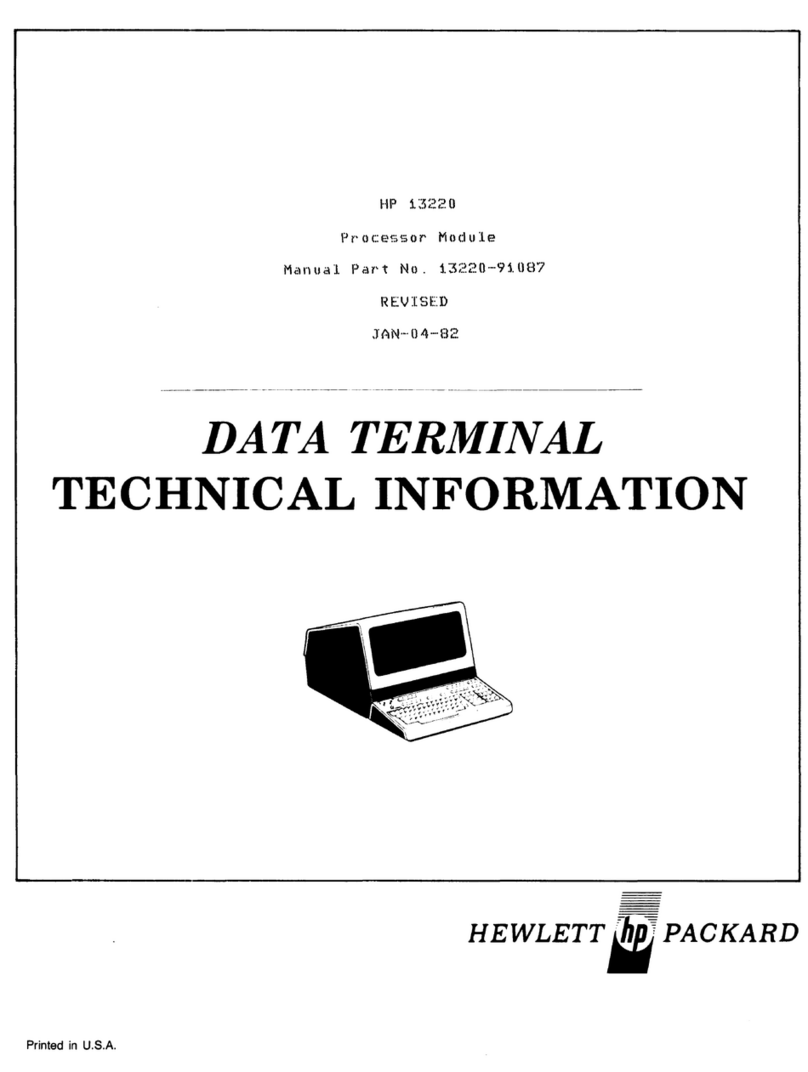
HP 262SA User manual

HEWLETT
(h~
PACKARD
Reference Manual
for
HP
262SA Dual-System Display Terminal
and
HP
2628A Word-Processing Terminal
Part
Number: 02625-90002

FEDERAL
COMMUNICATIONS COMMISSION
RADIO FREQUENCY INTERFERENCE STATEMENT
The
Federal Communications Commission (in 47 CFR 15.818)
has
specified
that
the
following
notice be
brought
to
the
attention
of
the
users of
this
product.
This
equipment
generates, uses,
and
can
radiate
radio frequency energy
and
if
not
installed
and
used
in
accordance
with
the
instructions
manual,
maycause interferenceto radiocommu-
nications.
It
has
been
tested
and
found to comply with
the
limits
for aClassAcomputingdevice
pursuant
to
Subpart
J
of
Part
15 of FCC Rules, which
are
designed to provide
reasonable
protection
against
such interference when operated in acommercial
environment.
Operation
of
this
equipment
in
aresidential
area
is likely to cause interference
in
which case
the
user
at
his
own expense will be required to
take
whatever'measures
may
be
required
to correct
the
in
terference.

r
Table
of
Contents
~
.. "
......
\' ,
Section
1
INTRODUCTION
Introduction . . .. .. . .. . . . . .. . . . . . . . . . . . . . . . . 1-1
Display Memory 1-3
Terminal Modes 1-4
Peripheral Device Connection
..
. . . .. . . . . . .
..
1-5
Configuration of the Terminal . . . . . . . . . . . . .
..
1-5
Data Communications ....................
..
1-5
Graphics . . . .. . . . . .
..
1-5
Word Processing .........................
..
1-5
Escape Sequences 1-5
Section
2
TERMINAL
CONTROL
Introduction 2-1
Selecting Modes 2-1
RemotelLocal Modes 2-1
Character/Block Modes . . . . . . .. . . . . . . . . . . . 2-2
Line Modify Mode .....................
..
2-3
Modify
All
Mode 2-3
Auto Line Feed Mode
..
. . . . . .. . . . . . . . . .
..
2-4
Display Functions Mode ..................2-5
Memory Lock Mode 2-6
Smooth Scroll Mode 2-7
Caps Lock Mode . . . . . .. . . . . . . . . . . . . . . . . . . 2-8
Format Mode . . . .. . . . . . . . . . . . . . . . . . .. . . . . 2-8
User Definable Function Keys ...............2-9
Defining Keys Locally (Definition Mode)
..
2-10
Defining User-Definable Function Keys
Programmatically 2.13
Controlling the User Key Menu
Programmatically ....................
..
2-15
Triggering the User Keys
Programmatically
...
. . . . .. . . . . . . . . . ..
..
2-15
Programmable RETURN Key 2-15
Controlling the User Key Labels
Programmatically 2-16
User Key Mode 2-16
Keyboard Data
Entry
..........
..
2-17
Keyboard Controls . . . . . . . . . . . . . . . . . . . . . .
..
2-17
Enable/Disable Keyboard . . . . . . .. . . . . . .. . 2-17
Soft Reset 2-18
Hard Reset 2-19
Break 2-20
Bell 2-20
Wait 2-20
Modem Disconnect 2-20
Section
3
CONFIGURING
THE
TERMINAL
Introduction ...............................3-1
Nonvolatile Memory 3-1
Configuration from the Keyboard ............3-1
Configuration Menus 3-2
How to Display aMenu 3-2
Modifying and Activating Configuration
Values 3-2
To
Return
to
Normal Operation . . . . . . . . . .. 3-4
Global Configuration ...................
..
3-4
Terminal Configuration 3-5
Datacomm Configuration 3-15
Choosing Buffer Sizes for Multipoint
Configurations 3-26
Programmatic Configuration 3-27
Configuration Escape Codes 3-27
Lock/Unlock Configuration Menus 3-28
Section
4
DISPLAY
CONTROL
Introduction ...............................
4-1
Cursor Controls 4-2
Home Up 4-2
Home Down 4-3
Move Cursor Up .......................
..
4-3
Move Cursor Down 4-3
Move Cursor Right 4-4
Move Cursor Left ........................4-4
Screen Addressing 4-4
Workspace Addressing 4-5
Cursor-Relative Addressing 4-6
Combining Addressing Methods ........... 4-8
Cursor Position Sensing 4-8
Window Control ......................
..
4-8
Roll
Text
Up 4-9
Roll
Text
Down ..........................4-9
Next Page!Previous Page 4-10
Edit
Operations 4-11
Insert Line .......................
..
4-12
Delete Line 4-12
Insert Character 4-12
Insert Character with Wraparound 4-14
Delete Character 4-16
Delete Character with Wraparound 4-17

Clear Display 4-18
Clear Line 4-19
Setting and Clearing Margins 4-19
Setting and Clearing Tabs 4-20
Tab
4-21
Back Tab 4-22
Display Enhancements
4-22
Section
5
DESIGNING AND
USING
FORMS
Introduction ...............................
5-1
Data Fields
on
aData Entry Form . . . . . . . . . . .
5-2
Protected Data Fields
5-2
Unprotected Data Fields
5-2
Transmit-Only Fields
5-2
Security Fields
5-2
How
to Design Data Entry Forms . . . . . . . . . . .
5-3
Line Drawing Character Set . . . . . . . . . . . .. . .
5-3
Drawing Forms Using the Function Keys
...
5-4
Transmit Modified Fields .................
5-6
Defining Fields Programmatically
5-6
How
to Transfer Forms from the Screen
to aHost Computer . . . . . . . . . . . . . . . . . . . . . . .
5-7
Enabling and Disabling Format Mode . . . . . . . . 5-9
Terminal Operation in Format Mode
5-9
Cursor Behavior
5-9
Display Control Functions in
Format Mode . . . . .. . .. . . . . .. . . .. . . . . .. . .
5-9
How
to Send Format Mode Data
to aHost Computer 5-10
Section
6
PERIPHERAL
DEVICES
Introduction . . . . . . . . . . . . . . . . . .. . . . . . . . . . . . .
6-1
Supported Plotters .........................
6-2
Supported External Printers
6-3
External Device Installation
6-3
Plotter Control
6-7
External Printer Operations 6-7
Selecting the External Printer as the
Destination Device
..
. . . . . . . . . . . . . . . . . . . . . .
6-7
Paper Movement 6-8
Record Mode
..
. . .. . .. . . . .. . . . .. . . . . . .. . .. .
6-8
Data Logging Modes
6-9
Log
Top Mode ...........................
6-9
Log
Bottom Mode 6-10
Terminal to Printer Data Transfers
6-11
Copy Line . . . . . . . . . . . . . . . . . . . . . . . . . . . . . . 6-11
Copy Page
6-12
Copy
All
6-12
Copy the Entire Active Workspace 6-13
ii
Computer to Printer Data Transfers 6-13
Binary Data Transfer 6-13
ASCII Data Transfer 6-14
Determining ifYour Escape Sequence
Command Has Been Successfully
Performed.
6-
14
Section
7
DATA COMMUNICATIONS
Introduction ...............................
7-1
Point-to-Point or Multipoint 7-2
Point-to-Point Considerations 7-4
Hardwired Connections ...................7-5
Modem Connections 7-6
Point-to-Point Installation 7-6
Point-to-Point Cabling 7-7
Point-to-Point Configuration 7-10
Point-to-Point Programming Information 7-10
Character Mode 7-10
Multicharacter Transfers 7-10
'Start and Stop Bits
7-11
Parity Checking 7-11
Receive Buffer 7-12
Receive Errors 7-12
Local/Remote Modes 7-12
Full Duplex Operation 7-13
Pacing Mechanisms 7-13
Multipoint Considerations 7-15
Asynchronous/Synchronous Decisions . . . . . 7-16
Hardwired Modem Decisions 7-16
Hardwired Connections 7-18
Modem Connections 7-18
Multipoint Installation 7
-19
Multipoint Cabling 7-20
Multipoint Configuration ................
..
7-23
Multipoint Programming Information .......7-23
Polling and Selecting 7-23
Character Mode Transfers 7-30
Block Mode Transfers 7-31
Multipoint Operating States 7-38
HP
Multipoint Protocol Control
Sequences .............................7-40
Monitor Mode ........................
..
7-43
Malfunction in aMultipoint Environment ...7-46
Section
8
STATUS
Introduction ...............................
8-1
Status Transfer Handshaking 8-2
Status Transfer Priority 8-3
Terminal Identification .....................8-3
Interpreting Status .........................8-3
."
r
Terminal Status
8-4
Primary Terminal Status 8-4
Secondary Terminal Status
8-7
Terminal Capabilities 8-10
Device
Status
8-15
Section
9
BLOCK DATA
TRANSFERS
Introduction . . .. . .. . . . . . .. . . . . . . .. . . . . . .. . .
9-1
Handshaking
9-1
Handshake Types
9-1
Handshake Mode Selection 9-2
Permanent Block Mode
9-5
Handshake Priority
9-5
DC1
Trigger Reset
9-5
DC2
Transfer . .. . . . . .. . . . . . . . . .. . . . . . . .. .
9-6
ENTER Key Data Transfers . . . . . . .. . . . .. . . .
9-6
Data Transfer Event Sequence . . .
9-7
Non-Format Mode Data Transfer
9-9
Format Mode Data Transfer 9-10
Transfer End Characters
9-11
ENTER Key Data Transfer Summary
9-12
Send Display (Ec d)
9-18
Transmit Type Function Key Definition
String Transfer
...
. . . . . .. . . . .. . . . . . .. . .
..
9-18
User
Key
Definition String Transfer . . . . ..
..
9-18
Status Data Transfer ......................
9-20
Special Modes
..
. . . . . . . . . . . . . . . . . . . . . . . .
..
9-20
Auto Keyboard Lock Mode 9-20
Send Cursor Position Mode
9-21
Section
10
ERROR MESSAGES
Introduction
10-1
Error Messages
10-1
Section
11
TERMINAL MAINTENANCE
Introduction
11-1
Malfunction
at
Power On
11-1
Troubleshooting Procedures 11-2
Configuration Checking 11-2
Resetting the Terminal . . . . . . . . .
..
11-2
Terminal Self Test ....................
..
11-4
Preventive Maintenance
..
...............
..
11-5
Cleaning the Screen and Keyboard
11-5
Protecting Non-Volatile Memory
11-5
Display Adjustments
11-6
Appendix
A
ESCAPE
CODES
Introduction A-I
Appendix
B
KEYBOARDS AND
CHARACTER
SETS
Alternate Character Sets B-1
Selecting Alternate Character Sets B-1
The Math Character Set ...............
..
B-3
The Line Drawing Set
...
..............
..
B-3
Support for International Languages B-4
7-Bit
Vs
8-Bit Operation B-5
Extended Characters Mode B-IO
Appendix
C
INTEGRAL
PRINTER
CONTROL
Introduction
C-l
Selecting the Integral Printer as the
Destination Device
C-2
Paper Movement
C-2
Printer Modes
C-2
Continuous Forms Mode
C-3
Report Format Mode
C-3
Metric Format Mode .....................C-4
Expanded Characters Mode
C-5
Compressed Characters Mode .............C-6
Record Mode
C-6
Log
Top Mode
C-7
Log
Bottom Mode C-8
Printer Operations .........................C-9
Copy Line
C-9
Copy Page C-I0
Copy
All
C-IO
Copy the Entire Active Workspace
C-IO
Computer to Printer Data Transfers ........
C-ll
Printer Status C-l1
Printer Self Test
C-12
Maintaining the Integral Printer .........
..
C-13
Printer Paper C-13
Loading Printer Paper C-14
Appendix
D
GRAPHICS
Introduction
D-l
Graphics Display
D-l
Keyboard Graphics Functions D-2
Graphics Control Functions . . . . . .
..
D-3
Programmable Graphics Functions ..........D-3
Control Codes ...........................D-4
Commands D-4
Parameters D-6
Graphics Display Control D-7
Graphics Cursor Control D-7
Graphics Memory Control ................D-8
Graphics Drawing Mode Parameters D-9
Dra~ng
Modes
D-9
Drawing Patterns D-l1
iii

Area Fills ..............................
..
D-17
Selecting an Area Fill
Pattern
. . . . . . . . .
..
D-17
User Defined Area Fill Patterns D-18
Using Area Fill Patterns as Line Types D-19
Rectangular Area Fills D-20
Fill Rectangle, Absolute . . . . . . . . . . . . . . . D-21
Fill Rectangle, Relocatable
D-21
Polygonal Area Fills
D-21
Area Boundary Pen D-22
LiftlLower Boundary Pen D-23
Relocatable Origin D-23
Set Relocatable Origin, Absolute D-24
Set Relocatable Origin to Current
Pen Position
..
. . . . . . . . . . . . . . . . . . . . . .
..
D-24
Set Relocatable Origin
to
Graphics
Cursor Position D-24
Selecting the Graphics Default Parameters . . D-25
Plotting Sequences D-26
Pen Control D-27
Use Cursor as Next Data Point
..
. . . . . .
..
D-27
Rubberband Line Mode D-28
Draw aPoint
at
the Current
Pen Position D-28
Vectors . . . . . . . . . . . . . . . . . . . . . . . . . . . . . . . . . . D-28
ASCII Formats D-29
Binary Format . . . . . . . . . . . . . . . . . . . . . . .
..
D-31
Mixing Data Formats
....
...............D-34
Graphics Functions in Display Functions
Mode D-35
Graphics Hardcopy Operations D-37
Initiating aTransfer From the Keyboard .D-37
Using the Ec&p Escape Sequences . . . . D-37
Graphics Text D-38
Keyboard Control of Graphics Text . . . .
..
D-39
Program Control of Graphics Text . . . . .
..
D-40
Selecting the Graphics Default
Parameters D-44
Graphics Hard Reset . . . . . . . .
..
D-44
Compatibility Mode D-45
Compatibility Mode Configuration D-45
Graphics Data D-48
Graphics Data Format . . . . .. . . . . . . . . . . . . D-49
Text
D-51
4014
Emulation D-52
Programming Considerations D-53
Graphics Status
..
......................
..
D-53
Read Device ID
(Parameter=l)
D-56
Read Current
Pen
Position
(Parameter=
2)
D-57
Read Graphics Cursor Position
(Parameter=
3)
D-58
Read Cursor Position with Wait
(Parameter=
4)
D-58
iv
Read Display Size (Parameter=
5)
D-60
Read Device Capabilities
(Parameter=6)
.D-60
Read Graphics
Text
Status
(Parameter=
7)
D-61
Read Zoom Parameter
(Parameter=8)
D-61
Read
Relocatab1E!
Origin
(Parameter=9)
..
D-61
Read Reset Status (Parameter=10) D-62
Read Area Shading Capability
(Parameter=
11)
D-62
Read Graphics Modification Capabilities
(Parameter=
12)
D-62
Any Other Parameter ...................D-62
Appendix
E
AppendixF
3278/78
EMULATION
MODE
Introduction
F-l
The
mM
3270 Information Display System . . F-2
HP's
Emulation ofthe 3276/8 ...............F-3
Using Your Terminal in an
IBM Environment ......................
..
F-3
Host Operating Systems ..................F-3
Datacomm F-5
Modem Options F-6
Preparing Your Terminal For Use F-18
Pre-Installation Preparations F-18
Cable Connections ......................F-18
Switching Between Personalities F-20
Screen Display
at
Power On .............F-20
Configuring For IBM Mode F-21
Displaying
The
IBM Configuration Menu . F
-21
The"
IBM Keyboard F-24
IBM Character Keys F-25
Character Selection Keys ..................F
-26
Shift Key ............................
..
F
-26
Alt Key F-26
Shift Lock Key F-26
(A,a/A) Switch F-27
Field-Oriented Cursor Movement Keys F
-27
Tab
Forward ...........................F
-27
Back
Tab
F-27
New Line Key F-28
Home Key F-28
Character-Oriented Cursor Movement Keys . F-29
Vertical Movement Keys F-29
Scroll Function Keys
..
..................F-29
Horizontal Movement Keys ..............F-30
Backspace Key . . . . . .. . . . . . . .
..
F-30
Cursor Definition Keys . . . .. . . . . . . . . . . . . . . . F-30
Alternate Cursor Key F-30
Cursor Blink Key .......................F-30

Erasing The Display . . . .. . . . . . . . . . . . . . . .
..
F
-31
Clear Key . . . . . . . . . . . . . . . . . . . . . . . . . . . . . . F
-31
Erase
End
Of Field Key F
-31
Erase
Input
Key F-31
Tests, Errors, And Recovery . . . . . . . . . . . . .
..
F-32
System Request Key . . . . . .. . . . . . . . . . . . . . F-32
Test Key F
-32
Click Key . . .. . . . . . . . . . . . . . . . . . . . . . . . . . . F-32
Reset Key F-33
I/O Initiation And Program Interaction . . .
..
F
-33
Enter Key F-33
Program Function Keys ...............
..
F-33
Program Access Keys F-34
Cursor Select Key . . . . . . . . . . . . . . . . . . . .
..
F
-34
Attention Key . . . .. . . . . . . . . . . . . . . . . . . . .. F-35
Printer Function Keys F
-35
Print
Key . . . . . . . . . . . . . . . . . . . . . . . . . . . . . . F
-35
Identity Key . . . . .. . . . . . . . . . . . .
..
F-35
Device Cancel Key ......................F-35
Editing Capabilities . . .. . . . . . . . . . . . . . . . . . . . F-35
Insert Key F-36
Delete Key . . . . . . . . . . . . . . . . . . . . . . . . . . . . . F-36
Unique Displayable Characters F-37
The
Duplicate Key F-37
The Field Mark Key ....................F
-37
The
Display ..............................F-37
Video Enhancements F-38
Field Enhancements F-38
Application Programs ...................
..
F-39
Commands And Orders F-39
Commands F-39
Write Commands F-39
Read Commands F-40
Control Commands F-40
Orders .................................F-40
Buffer Control Orders .................F-40
Printout
Format
Orders F-41
Print
Operations F
-41
Copying
Data
To
An External
Printer
. .
..
F
-41
Copying
Data
To
The
Integral
Printer
. . . . F-42
Status Line
and
Error
Messages F-43
Differences Between IBM 3276
and
HP
2625A F-44
v

List
of
Illustrations
Screen/Display Memory Relationship
1-3
Primary Terminal Modes 1-4
User Keys Menu, Showing Default Values
2-10
Global Configuration Menu
3-5
Terminal Configuration Menu ...............
3-5
Full Duplex Hardwired Configuration
Menu
3-15
Full Duplex Modem Configuration Menu
3-15
Multipoint Asynchronous Menu
3-15
Multipoint Synchronous Menu
3-15
The "Roll" Data Functions 4-9
Previous Page and Next
;Page
Concepts 4-10
Character Insert with Margins
4-13
Character Insert with Wraparound 4-15
Character Delete with Margins .............
4-16
Delete Character with Wraparound
4-18
Sample Form Created Using Format
Mode
5-1
Sample Data Entry Form . . . . .. .. . . . .. . . .. . .
5-3
Line Drawing Set Keyboard Keys
5-4
Example Data Entry Form
5-4
FORMIO Source Listing
5-8
Plotter Connected in Eavesdrop
Configuration
6-5
HP
2625A
API Configuration
6-5
HP
2628A
API Configuration 6-6
Printer Connection to Standard
HP
2628A
. .
..
. . . .. . .. . . . .. . . . .. . . .. . . .. . .
6-6
Top Logging 6-10
Bottom Logging 6-10
Dual Connector (Options
026
and 046)
7-4
Point-to-Point Decision Tree
7-5
Terminal Rear
View
(Typical) ...............
7-6
Point-to-Point Hardwired Configuration
.....
7-7
Terminal Connection to an
HP
13265A
Modem Pod or an
HP
13266A
Current Loop Converter .
..
7-8
HP
Multipoint Decision Tree
7-15
HP
Multipoint Configuration
.(Leased Line, Multidrop)
7-17
HP
Multipoint Configuration
7-20
DSN Data Link Connection
7-21
Multipoint Terminal Addressing
7-24
Poll Sequence Format
7-25
Group Poll Sequences
7-26
Select Sequence Format ........
..
7-27
Group Select Sequences
7-27
Line Select Sequences 7-28
vi
Status Request Sequences
....
. . . . . . . . . . .
..
7-28
Typical Configuration Status Request
and Response Sequence 7-29
Configuration Status Byte Contents .
..
7-30
Examples of Block Transmissions
7-31
Operation of Block Protocol Control
Characters
(2
pages)
7-41
Communications Line Using aMonitor 7-44
Sample Data Transfers Displayed in
Monitor Mode ..........................7-45
Character Distortion in Group Poll 7-45
Data Overrun Indication ...................7-45
Terminal Primary Status Example 8-5
Terminal Primary Status Bytes 8-6
Terminal Secondary Status Example 8-8
Terminal Secondary Status Bytes 8-9
Terminal Capabilities (Alphanumeric
Typical) Status Example
8-11
Terminal Alphanumeric Capabilities
Status Bytes 8-12
Terminal Graphics Capabilities
Status Bytes 8-13
Installed Memory Status Bytes .............8-14
Terminal Interface Capabilities
Status Bytes 8-15
Device Status Example ............
..
8-16
Device Status Bytes 8-17
Modes Affecting
ENTER
Key Operation . . . . . 9-7
Initial
HP
Screen Display
11-1
Terminal Test
Pattern
11-4
Battery Support Location 11-6
Battery Replacement ....................
..
11-7
Screen Brightness Control 11-8
Math Character Set ........................B-3
Line Drawing Set Elements .................B-4
Swedish Keyboard .........................B-6
Norwegian Keyboard B-6
German Keyboard
..
.......................B-6
United Kingdom Keyboard B-7
Spanish Keyboard B-7
French Canadian Keyboard B-7
French Keyboard B-8
Italian Keyboard B-8
Dutch Keyboard B-8
Finnish Keyboard B-9
Danish Keyboard B-9
Extended Character Mode for
USASCII Keyboard
B-l1
Bit Mapping for Roman 8Character
Set
B-12
.
~.,
"',

r.,·
..
··,
~
..
Report and Metric Formats
C-4
Character Sizes and Enhancements as
Printed on the Integral Printer ......
..
C-5
Top Logging
C-8
Bottom Logging ....................... C-8
Integral Printer Test
Pattern
. . . . . . . . . . . .
..
C-12
Integral Printer Mechanism
C-13
Graphics Control Keys
D-2
Examples of Drawing Modes D-I0
Predefined Line Type Patterns D-12
Using Area Patterns as Line Types D-14
Examples of User Defined Line Types D-15
Area Paterns Examples . . . . .. . . .
..
D-16
How
the Area Fill Pattern
is
Mapped . . . . . . . D-17
Examples of User-Defined Area Fill
Patterns . . . . . . . . . . . . . . . . . . . . . . . . . . . . . . . D-19
Using Area Fill Patterns as Line Types
.....
D-20
Overlapping Polygon Area Fills D-22
Polygon Area Fill Example D-22
Relocatable Origin D-23
Example of Mixed Oata Formats
0-34
Displaying Graphics Sequences D-36
Graphics
Text
Characters
0-39
Graphics Text Sizes 0-41
Graphics Text Directions 0-41
Graphics Text Cursor Position .............
0-42
Turning On Compatibility Mode D-48
Comparison ofthe 4014 and the
HP
Terminal
0-49
Scaled Oata ..............................
0-50
Unscaled Oata D-50
Determining Address Bytes 0-51
Communication Line Configurations .........F-6
3276/8 Configuration Menu F
-21
IBM Key Locations on
HP
Keyboard F
-24
vii


Introduction
INTRODUCTION
1
Terminals covered by this manual
are
the
HP
2625A Dual System Display Terminal and
the
HP
2628A Word Processing Center. The standard 2625A can operate as an
HP
terminal,
similar to an
HP
2622A Display Terminal, or simulate an
IBM·
3276 Control UnitlDisplay
Station. The
standard
2628A is similar to
the
2625A, without
the
IBM terminal simulation
capability,
but
with
the
HPWORD word-processing capability. (The 2625A also has
the
HPWORD word-processing capability, as an option.) The features of
the
standard
2625A and
standard 2628A, and
the
options of both,
are
listed below.
OPTION 2625A 2628A
Std
HP/IBM
dual
personality
terminal.
Word processing
terminal.
Port
1:
Datacomm
port
for connec-
Port
1:
DSN
port.
tion
to a
Distributed
Sys-
tems
Network
(DSN).
001
002
004
005
006
007
008
009
010
011
012
013
014
015
016
021
Port
1:
RS-232-C
or
RS-422
datacomm
port.
Port
2:
IBM Bisync
datacomm
port.
Swedish keyboard.
Norwegian
keyboard.
German
keyboard.
United
Kingdom
keyboard.
Spanish
keyboard.
French
Canadian
keyboard.
French
keyboard.
Italian
keyboard.
Dutch
keyboard.
Finnish
keyboard.
Danish
keyboard.
240V, 50 Hz
100V, 60 Hz
220V, 50 Hz
100V, 50 Hz
Port
1:
RS-232-C
or
RS-422
datacomm
port.
Port
2:
RS-232-C
or
RS-422
printer/plotter
port.
Swedish keyboard.
Norwegian
keyboard.
German
keyboard.
United
Kingdom
keyboard.
Spanish
keyboard.
French
Canadian
keyboard.
French
keyboard.
Italian
keyboard.
Dutch
keyboard.
Finnish
keyboard.
Danish
keyboard.
240V, 50 Hz
100V, 60 Hz
220V, 50 Hz
100V, 50 Hz
•
IBM
is a
trademark
of International Business Machines Corporation.
1-1

Introduction
OPTION 2625A 2628A
022
Port
1:
Datacomm
port
for
Port
1:
Datacomm
port
for connec-
connectionto
an
HP
13265A
tion
to
an
HP
13265A
modem or
an
HP
13266A
modem
or
an
HP
13266A
Current
Loop Adapter.
Current
Loop Adapter.
026
Port
1:
Dual
port;
standard
da
tacomm
and
Alternate
Pe-
ripheral
Interface ports.
(Supplied only
with
graphics. option
523.)
027
Port
1:
First
multipoint
async/sync
Port
1:
First
multipoint
async/sync
terminal
port.
First
termi-
terminal
port.
nal
in
a
multipoint
network
must
have
this
option.
028
Port
1:
Async
multipoint
daisy
Port
1:
Async
multipoint
daisy
chain
terminal
port.Anyter-
chain
terminal
port.
minal
except
the
first
in
an
async
multipoint
network
must
have
this
option.
038
Port
1:
Same
as
option 028, except
Port
1:
Same
as
option 028, except
usedfor sync
multipoint
con- usedfor sync
multipoint
con-
figurations. figurations.
046
Port
2:
Dual port; external
printer
and
Alternate
Peripheral
Inter-
face ports. (Supplied only with
047
Port
2:
First
IBM Bisync
terminal
graphics option
523.)
port.
First
terminal
in
an
IBM Bisync network
must
have
this
option.
048
Port
2:
IBM Bisync daisy
chain
ter-
minal
port.Any
terminal
ex-
cept
the
first
in
an
IBM
Bisync network
must
have
this
option.
050
Integral
printer.
Integral
printer.
061
Green
CRT. Green CRT.
062 Amber CRT. Amber CRT.
401
Tilt
and
swivel base.
Tilt
and
swivel base.
523 Graphics capability. Graphics capability.
528 HPWORD word processing capabil-
ity
1-2

Introduction
DISPLAY MEMORY
A
portion
of
terminal
memory, called display memory, is
reserved
for
storing
data
for display
on
the
screen.
For
the
HP
2625A, display
memory
consists of
an
HP
workspace
and
an
IBM
workspace (figure 1-1).
Of
course,
the
HP
2628A
has
only
an
HP
workspace.
The
part
of
the
workspace displayed
on
the
screen
is called
the
window.
Display
~
r
wor~
Currently
Active
Workspace
IBM
Workspace
Window
Figure
1-1. ScreenlDisplay Memory
Relationship
1-3

Introduction
TERMINAL MODES
The
terminal
operates
in
a
variety
ofmodes, some ofwhich
are
selectable
using
the
function
keys;
others
are
selected
on
the
configuration menus.
The
primary
modes
are
illustrated
in
figure 1-2
and
listed below.
I
Local
Modes
I
I
Char
h
Non- Format
Format
I
Remote
I
I
Non-
Format
I
Line
I
Format
I
Block
I
I
Non-
Format
I
Page
I
Format
•Local
•Remote
•
Character
•Block
•Line
•
Page
•
Format
•Non-Format
1-4
Figure
1-2.
Primary
Terminal Modes
Data
entered
from
the
keyboard is displayed on
the
screen,
but
the
terminal
is disconnected from
the
host computer.
The
terminal
is connected to
the
host computer.
Data
entered
from
the
keyboard is
transmitted
to
the
computer,
and
data
received from
the
computer is displayed on
the
screen.
Active only
in
Remote mode.
Data
is
transmitted
to
the
host
computer,
one
character
at
atime.
Active only
in
Remote mode.
Data
is
transmitted
to
the
computer
in
blocks; selectable
as
one line
per
block,
or
as
one page
per
block.
Active only
in
Remote Block mode.
Data
is
transmitted
to
the
host
computer
in
blocks, each consisting of one line.
Active only
in
Remote Block mode.
Data
is
transmitted
to
the
host
computer
as
ablock, consisting of one
page
(one screenful).
Active only
in
Remote mode. Used to transfer, to
the
host
computer,
data
entered
into
data
entry
forms, which
are
displayed on
the
screen.
Enables
restriction of
entry
data
to selected fields on
the
form,
and
restriction
to selected
data
types (numeric, alphabetic,
or
unrestric-
ted).
Terminal
operates normally. No
restriction
on
data
entry.

Introduction
PERIPHERAL DEVICE CONNECTION
Peripheral
devices,
such
as
printers
and
plotters,
are
connected to
the
terminal
in
an
Alternate
Peripheral Interface network.
Either
the
standard
2628A, option 046 (2628A),
or
option
026
(2625A) is
required
to
connect to
an
Alternate
Peripheral
Interface
network.
CONFIGURATION OF THE TERMINAL
Configuration
of
the
terminal
is performed
using
menus.
These
include aGlobal
Configuration
menu,
a
Terminal
Configuration
menu,
and
four
data
communication
(datacomm)
menus
for
the
HP
personality
of
the
2625A
and
for
the
2628A.
The
IBM
personality
of
the
2625A
has
a
menu
of
its
own. Selections
made
on
these
menus
determine,
among
other
things,
terminal
characteristics,
coordination of
data
transfer
between
the
terminal
and
the
host
computer,
parity
type,
and
rate
of
data
transfer.
DATA
COMMUNICATIONS
The
terminal
can
be connected
to
an
HP
host
computer
in
either
apoint-to-point
or
multipoint
configuration,
either
hardwired
or
through
modems.
Port
2
of
the
standard
2625A
terminal
is
connected to
an
IBM
computer
in
a
multipoint
network, for Bisync
operation.
In
addition,
option 021
of
either
the
2625A
or
the
2628A
can
be connected to a
distributed
systems
network
(DSN), aform
of
multipoint
network.
The
2628A
or
the
HP
personality
of
the
2625A
can
transfer
data
either
one
character
at
a
time
or
in
blocks of one
line
or
one
page
(one screenful)
at
rates
up
to 19,200
baud.
Switching
between
the
HP
and
IBM
personalities
of
the
2625A
terminal
isdone
with
afunction
key.
Each
port
remains
active, even
though
it
is
not
currently
selected.
GRAPHICS
Option 523
incorporates
a
graphics
capability
into
both
the
2625A
and
the
2628A
terminals.
Refer to Appendix Dfor information.
WORD PROCESSING
Option 528
incorporates
the
HPWORD word processing
capability
into
the
2625A
terminal.
This
capability
is
standard
with
the
2628A. Appendix E
contains
information
on word process-
ing.
ESCAPE SEQUENCES
Escape sequences,
incorporated
into
a
computer
program,
enable
the
program
to control
terminal
operations.
When
the
terminal
receives
the
escape sequence,
it
performs
the
opera-
tion
specified
in
the
sequence.
Escape
sequences consist
of
most
of
the
operations
performable
at
the
keyboard,
using
the
non-alphanumeric
keys.
Many
sequences
are
also
enterable
from
the
keyboard. References to escape sequences
are
made
throughout
the
manual.
Refer
to
Appendix Afor acomplete
list
of
the
escape sequences
and
their
functions.
1-5


Terminal
Control
INTRODUCTION
2
This
section describes
the
modes
in
which
the
terminal
can
operate,
use
of
the
function keys,
enabling
and
disabling
the
keyboard,
and
resetting
the
terminal.
SELECTING MODES
Pressing
the.
key
enables
the
mode selection keys
and
changes
the
function
key
labels
to
the
following:
...
EmlillIID!m.
EEmI
IIi1WJIg
ilia.
~
IIIIil!IBI
These
keys
act
as
toggle
switches
in
that
they
alternately
enable
and
disable
the
designated
mode.
When
a
particular
mode is
enabled,
an
asterisk
is displayed
in
the
label.
Remote/Local Modes
When a
communications
link
exists
between
the
terminal
and
a
remote
host
computer,
the
terminal
is
in
either
of
the
following two modes:
•Remote Mode.
In
this
mode,
when
you
press
an
alphanumeric
key
the
associated
ASCII
code is
transmitted
to
the
host
computer
.
•Local Mode.
In
this
mode,
when
you
press
an
alphanumeric
key
the
associated
character
is
displayed
at
the
current
cursor
position
on
the
screen
(nothing
is
transmitted
to
the
host
computer).
From
the
keyboard,
you
switch
the
terminal
back
and
forth
between
Local
and
Remote
modes
using
the
REMOTE
MODE
key.
From
the
keyboard
or
auser-definable key, you
can
switch
the
terminal
from local
to
remote
(and
vice versa)
using
the
following escape sequences:
Local: Ec
&kOR
Remote: Ec &k1R
2-1

Terminal
Control
ARemote/Local mode
designator
is
maintained
in
non-volatile memory. When you
change
modes
using
the
REMOTE
MODE
key, you also
alter
that
mode
designator
in
non-volatile
memory.
When
you
change
modes
using
the
escape sequences, however,
the
designator
is
not
altered.
After
a
hard
reset
or
turning
off
the
power,
the
terminal
reverts
to
the
mode specified
by
the
remote/local
designator
in
non-volatile memory.
Character/Block Modes
When
the
terminal
is connected on-line to aremote
host
computer,
it
operates
in
either
of
the
following
data
transmission
modes:
•
Character
Mode.
In
this
mode,
data
is
transmitted
a
character
at
a
time
as
it
is
entered
through
the
keyboard. ASCII control codes (such
as
<CR>
and
<LF»
are
transmitted.
•Block Mode.
In
this
mode,
data
is
not
transmitted
at
the
time
it
is
entered
through
the
keyboard.
Instead,
you
transmit
an
entire
block of
data
by
first
typing
the
data
(after
initially
typing
the
data
you
can
move
the
cursor
around
and
edit
the
data
as
desired)
and
then
pressing
the.
key.
When
the
terminal
is
in
Block mode, ASCII control codes (such
as
<CR>
and
<LF
»
are
acted
upon locally
but
are
not
usually
transmitted
with
the
data
block (refer
to
Section 9for
detailed
information
on Block mode
data
transfers).
From
the
keyboard, you
enable
and
disable Block mode
using
the
BLOCK
MODE
key.
From
a
program
executing
in
a
host
computer, you
enable
and
disable Block mode
using
the
following escape sequences:
ENABLE: Ec &k1B
DISABLE: Ec &kOB
ACharacter/Block mode
designator
is
maintained
in
non-volatile memory. When you
change
modes
using
the
BLOCK
MODE
key, you also
alter
that
mode
designator
in
non-volatile memory.
When
you
change
modes
using
the
escape sequences, however,
the
designator
is
not
altered.
After
a
hard
reset
or
turning
off
the
power,
the
terminal
reverts
to
the
mode specified by
the
Character/block
designator
in
non-volatile memory.
The
relationship
between
Block, Line, Page,
and
Format
modes
is
described
under.
key
later
in
this
section.
2-2

Terminal Control
Line Modify Mode
When
the
terminal
is
in
Remote mode
and
Character
mode,
and
you
are
communicating
interactively
with
a
host
computer, you
may
sometimes
enter
an
erroneous
character
string
to which
the
computer
responds
with
an
error
message.
If
the
character
string
is
a
lengthy
one
and
the
error
consists
of
only afew
characters,
it
is a
nuisance
to
have
to
retype
the
entire
string.
In
such
acase, you
may
instead
enable
Line Modify mode (which
temporarily
switches
the
terminal
to aspecial form ofBlock mode).
You
may
then
move
the
cursor
to
the
erroneous
line
on
the
display
and
correct
the
character
string.
When
the
string
is
edited
to
your
satisfaction, you
retransmit
the
line
to
the
host
computer
by
pressing
either
the
1:1
key
or
the.
key.
Note
that
while
Line
Modify mode
results
in
ablock
transmission,
it
is
completely
indepen-
dent
of
the
Block mode function described
earlier
in
this
section (you do
not
have
to
first
enable
Block mode).
In
fact, Line Modify mode is a
feature
that
was
specifically
designed
for
use
when
the
terminal
is
operating
in
Character
mode,
and
will function only
in
Character
mode.
From
the
keyboard, you
enable
Line
Modify mode
using
the
LINE
MODIFY
key.
Line
modify
mode is
automatically
disabled
when
you
press
either
1:1
or
•.
If
you
change
your
mind
and
wish to
disable
Line
Modify mode before
retransmitting
the
command
string,
press
the
LINE
MODI
FY
key
again
and
the
terminal
will
return
to
normal
Character
mode.
For
each
line,
the
terminal
remembers
the
position of
the
first
character
entered
from
the
keyboard.
Then
when
you
re-transmit
aline
in
modify mode, only
the
portion
of
the
line
entered
from
the
keyboard
is
retransmitted;
any
prompt
characters
preceding
the
command
string
are
ignored
by
the
terminal.
For
more
detailed
information
about
this
feature
refer
to
the
discussion
of
the
Start
Col
field
of
the
Terminal
Configuration
menu
in
Section 3.
Modify
All
Mode
When
the
terminal
is
in
Character
mode, you
can
enable
ModifyAll mode,
which
switches
the
terminal
to aspecial form
of
Block mode. Modify All mode
is
the
same
as
Line
Modify mode
except
that
it
is
not
disabled
when
you
press
1:1
or
•.
From
the
keyboard, you
enable
and
disable
Modify All mode
using
the
MODI
FY
ALL
key.
From
a
program
executing
in
a
host
computer, you
enable
and
disable
Modify All mode
using
the
following escape sequences:
ENABLE:
Ec
&k1M
DISABLE: Ec
&kOM
AModify All mode
designator
is
maintained
in
non-volatile memory.
When
you
change
modes
using
the
MODI
FY
ALL
key, you also
alter
that
mode
designator
in
non-volatile
memory.
When you
change
modes
using
the
escape sequences, however,
the
designator
is
not
altered.
2-3

Terminal Control
After
a
hard
reset
or
turning
off
the
power,
the
terminal
reverts
to
the
mode specified by
the
modify all
designator
in
non-volatile memory.
Auto Line Feed Mode ,
When Auto Line Feed mode is enabled,
an
ASCII
line
feed control code is
automatically
appended to
each
ASCII
carriage
return
control code
generated
through
the
keyboard.
That
is,
every
<CR>
code
generated
through
the
keyboard becomes a
<CR>
<LF>.
ASCII
carriage
return
control codes
can
be
generated
through
the
keyboard
in
any
of
the
following ways:
•By
pressing
the
CI
key, provided
that
a
<CR>
code
is
included
in
the
key
definition.
•By
simultaneously
pressing
the
III
andm
keys.
•By
pressing
any
of
the
user
keys
(_
through
II1II), provided
that
a
<CR>
code is
included
in
the
particular
key
definition.
•By
pressing
the.
key
when
the
terminal
is
in
Block mode, Line Modify mode,
or
Modify
All mode (in
these
cases a
<CR>
code is
transmitted
as
the
line
terminator).
From
the
keyboard, you
enable
and
disable Auto Line Feed mode
using
the
AUTO
IF
key.
From
a
program
executing
in
a
host
computer, you
enable
and
disable
Auto
Line
Feed
mode
using
the
following escape sequences:
ENABLE: Ec &k1 A
DISABLE: Ec &kOA
When you
enable
or
disable
Auto
Line Feed mode
using
the
AUTO
LF key, you also
alter
the
content
of
the
~~AutoLF"
field
in
both active
and
non-volatile memory.
When
you
enable
or
disable
Auto
Line Feed mode
using
the
escape sequence, however, you only
change
the
content
of
the
Au
t
elF
field in active memory.
After
a
hard
reset
or
turning
off
the
power,
the
terminal
reverts
to
the
mode specified by
the
Au
t
elF
field
in
non-volatile memory.
2-4
This manual suits for next models
1
Table of contents
Other HP Touch Terminal manuals

HP
HP Engage Go Convertible System Operating and maintenance manual

HP
HP Engage Go Convertible System User manual

HP
HP rp5800 Assembly instructions

HP
HP Engage One Retail System 141 Manual

HP
HP RP7 Model 7800 User manual

HP
HP Rp5000 - Point of Sale System User manual

HP
HP Engage Go 10 User manual

HP
HP Rp5000 - Point of Sale System Specification sheet

HP
HP Engage One Pro User manual

HP
HP ap5000 User instructions