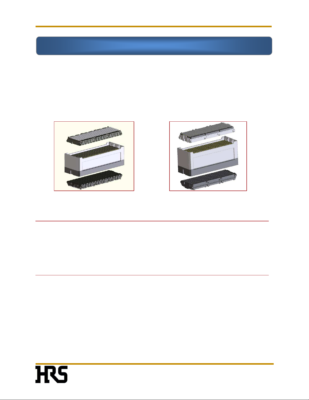
HRS Hirose IT3 Quick start guide

IT3/IT5
Connector System
A
SSEMBLY
N
OTES
Document Number:
ETAD-F0458
Revision 3.10
Hirose IT3/IT5 ™
Connector System
G
ENERAL
I
NFORMATION
-
D
ESIGN
N
OTES
-
PWB
A
SSEMBLY
N
OTES
-
T
IPS FOR
SMT
A
SSEMBLY
-
S
YSTEM
A
SSEMBLY
-
S
YSTEM
D
ISASSEMBLY
Winner of 2009 SMT V
ision
Award
Nov.1.2022Copyright2022HIROSEELECTRICCO.,LTD.AllRightsReserved.

IT3/IT5
Connector System
T
ABLE OF
C
ONTENTS
Document Number:
ETAD-F0458
Revision 3.10
Page i
Section Title Page
1.0 Introduction 1
1.1
Purpose 1
1.2
Scope 1
1.3
Applica tion and nterpreta tion 2
2.0 General Information 3
2.1
Component Weights 4
2.2
Differences between T3 and T5 Connector Pa rts 8
2.3
Pa rt Number Designation 9
2.4
Manufacturing Lot Number 10
2.5
Receptacle General Dimensions 11
3.0 PWB Design Information 12
3.1
Component Footprint 13
3.2
Multi -Connector Sys tems 18
3.3
Spacers 19
3.4
Clea rance Between Connectors 20
3.5
nterposer Di rection 22
3.6
Alignment Tolerances 23
4.0 Introduction to Assembly 24
5.0 Stencil Printing 24
5.1
Solder Pas te Selection 24
5.2
Stencil Design 25
5.3
Effect of Alignment 25
5.4
Pas te Print Quality 26
6.0 Pick and Place 27
6.1
Pa ckaging 27
6.2
Media Tra ys 28
6.3
Pre-bake 29
6.4
Pi ck Point 29
6.5
Component Weight 30
6.6
Vision a nd Alignment 30
6.7
Pla cement Force 31
6.8
Orienta tion ndicator 31
7.0 Reflow Processing 32
7.1
nstrumentation 32
7.2
Thermocouple Atta chment 32
7.3
Reflow Profile Considera tions 33
7.4
Suggested Thermal Profile Ranges 33
7.5
Other mportant Fa ctors 33
7.6
Nitrogen Envi ronment 34
7.7
Double Sided Reflow 34
7.8
Mi xing Tin-Lead and Lead-Free 34
Nov.1.2022Copyright2022HIROSEELECTRICCO.,LTD.AllRightsReserved.

IT3/IT5
Connector System
T
ABLE OF
C
ONTENTS
Document Number:
ETAD-F0458
Revision 3.10
Page ii
7.9
Al ternati ve Alloys 35
7.10
Metal Cap Removal 35
8.0 Cleaning 37
8.1
Water Washable Solder Process 37
8.2
Saponi fiers 38
8.3
No-Clean Solder Process 38
8.4
Cleanliness Testing 39
9.0 Inspection 40
9.1
Sampling Frequency 40
9.2
X-Ra y La minography 40
9.3
Visual nspection 40
9.4
X-Ra y Analysis and Voiding 41
9.5
Trans mission 2-Dimensional X-Ra y 41
9.6
Automa tic nspection Optimization 42
10.0 Rework 43
10.1
Equipment and Supplies 43
10.2
Profiling 43
10.3
Reflow Profile Considera tions 44
10.4
Suggested Thermal Profiles 44
10.5
Special Profiling Considera tions 45
10.6
Receptacle Removal 45
10.7
Site Redressing 46
10.8
Solder Replenishment 48
10.9
Receptacle Repla cement 48
10.10
Reflow Soldering 49
10.11
nspection 49
10.12
Rework Solder Paste Selection 49
11.0 Tips for SMT Assembly 51
11.1
Stencil Printing 51
11.2
Pi ck and Place 55
11.3
Reflow 56
11.4
X-Ra y nspection 58
11.5
Rework 59
12.0 System Level Assembly 62
12.1
nterposer nstallation 62
12.2
Manual Assembly 64
12.3
nstallation Cap 65
12.4
Assembly Fi xturing 66
13.0 System Level Disassembly 70
13.1
Daughter ca rd removal 70
13.2
nterposer Assembly removal 71
Nov.1.2022Copyright2022HIROSEELECTRICCO.,LTD.AllRightsReserved.

IT3/IT5
Connector System D
OCUMENT
H
ISTORY
Document Number:
ETAD-F0458
Revision 3.10
Page iii
Revision
No. Description (Major changes) Date
1.0 nitial release April 6, 2009
1.1 Revised spacer and nut ti ghteni ng information May 18, 2009
1.2 Revised information on 300 positi on receptacles to
include metal stiffening ca p
August 26, 2009
1.5 Revised sta ck height cha rts , press force informa tion and
other informa tion wi th respect to design note release
November 30,
2009
1.55 Updated the front page and revised information on
footprint
December 30,
2009
1.56 Updated rework a nd packaging information December 13,
2010
1.6 Updated height va ria tion chart and interposer
installation cap
February 24,
2011
2.0 ncluded information on plugs and an interposer removal
tool
May 1, 2011
3.0 ntegra ted T5 information July 15, 2011
3.10 ncluded T5H informati on May 21, 2012
Nov.1.2022Copyright2022HIROSEELECTRICCO.,LTD.AllRightsReserved.

IT3/IT5
Connector System G
ENERAL
I
NFORMATION
Document Number:
ETAD-F0458
Revision 3.10
Page 1 of 73
Hirose IT3 connector assembly Hirose IT5 connector assembly
The Hirose IT3/IT5 connector system is a three-piece mezzanine connector. Process-friendly BGA
receptacles are assembled onto P Bs, and separate, configurable interposers complete the
connections between circuit boards. It is available in 100, 200 and 300 signal model. IT3 is
available with tin-lead or lead-free alloy solder balls and IT5 is available in lead-free alloy solder
balls.
1.1 Purpose
This technical bulletin is intended to provide basic information and product features of the
irose IT3/IT5 BGA connector system. By providing this information, irose believes it can help
its customers to speed product development, improve quality and reliability, and limit overall
system costs.
1.2 Scope
This guideline provides information useful for applications using the IT3/IT5 BGA connector
system. It provides information pertaining to:
a) General overview of the connector system
b) Configuration and part numbering
c) PWB design
d) Assembly processing, inspection and repair
This document will be updated by irose as required to reflect current technologies and
manufacturing capabilities.
Section 1 Introduction
Nov.1.2022Copyright2022HIROSEELECTRICCO.,LTD.AllRightsReserved.

IT3/IT5
Connector System G
ENERAL
I
NFORMATION
Document Number:
ETAD-F0458
Revision 3.10
Page 2 of 73
1.3 Application and Interpretation
This technical bulletin is intended to offer only general guidance and design concepts to
customers. Therefore, it does not limit customer designs nor guarantee results under all
situations. Development of actual designs is the responsibility of each customer. Customers
should consult with irose regarding their specification, when, or if, any questions arise relating
to these guidelines. Use of this technical bulletin is at customer’s sole risk. This bulletin is
provided
“AS IS”
and without warranty of any kind and irose
EXPRESSLY DISCLAIMS ALL
ARRANTIES, EXPRESS OR IMPLIED, INCLUDING, BUT NOT LIMITED TO THE IMPLIED ARRANTIES OF
MERCHANTABILITY AND FITNESS FOR A PARTICULAR PURPOSE. HIROSE DOES NOT ARRANT THAT THE
GUIDELINES CONTAINED IN THIS BULLETIN ILL MEET ANY CUSTOMER’S REQUIREMENTS.
FURTHERMORE, HIROSE DOES NOT ARRANT OR MAKE ANY REPRESENTATIONS REGARDING THE USE
OR THE RESULTS OF THE USE OF INFORMATION CONTAINED IN THIS BULLETIN IN TERMS OF
CORRECTNESS, ACCURACY, RELIABILITY, OR OTHER ISE. UNDER NO CIRCUMSTANCE SHALL HIROSE OR
ITS DIRECTORS, OFFICERS, EMPLOYEES OR AGENTS BE LIABLE FOR ANY INCIDENTAL, SPECIAL OR
CONSEQUENTIAL DAMAGES (INCLUDING DAMAGES FOR LOSS OF BUSINESS, LOSS OF PROFITS, BUSINESS
INTERRUPTION, LOSS OF BUSINESS INFORMATION AND THE LIKE) ARISING OUT OF THE USE OF THE
INFORMATION CONTAINED IN THIS BULLETIN.
Nov.1.2022Copyright2022HIROSEELECTRICCO.,LTD.AllRightsReserved.

IT3/IT5
Connector System G
ENERAL
I
NFORMATION
Document Number:
ETAD-F0458
Revision 3.10
Page 3 of 73
Hirose’s IT3/IT5 connector system is designed to provide modular high-speed differential,
single-ended and power connections between two parallel boards. The interconnection to the
P Bs utilizes process-friendly Ball Grid Array receptacles, while the stacking height of 15 to
40mm for IT3 and 18 to 40mm for IT5 is set by an impedance-controlled interposer that is added
at the system level.
The IT3/IT5 connector system consists of two receptacles and one interposer. The receptacles
have low profiles and open bodies. The BGA balls are mounted on compliant pins and are set on
a staggered grid of 1.5 and 1.75 mm pitch. Both the mating and mounting receptacles’
footprints are compatible with popular mezzanine connectors. Receptacles are available in tin-
lead and lead-free configurations for IT3 and lead-free for IT5. They can be used in no-clean or
water-wash assembly processes.
The interposer is an assembly consisting of individual wafers, each carrying 10 signal and 9
ground connections for IT3, and 10 signal and 11 ground connections for IT5. The interposer is
mounted to the receptacles and locked in with mechanical latches to create highly reliable and
stable mechanical and electrical connections. IT3 and IT5 interposers and receptacles are
interchangeable.
Section
2 General Information
Mating
receptacle
Interposer
assembly
Mating Side
Mounting
receptacle
Mounting Side
Interposer for
IT5
Signal
Ground
Signal / Ground Configuration
Interposer for
IT3
Signal
Ground
Signal / Ground Configuration
IT3D
-
***S
-
BGA(**)
IT3M
-
***S
-
BGA(**)
IT5
*
D
-
***S
-
BGA(**)
IT5*
M
-
***S
-
BGA(**)
Polarity
Polarity
Nov.1.2022Copyright2022HIROSEELECTRICCO.,LTD.AllRightsReserved.

IT3/IT5
Connector System G
ENERAL
I
NFORMATION
Document Number:
ETAD-F0458
Revision 3.10
Page 4 of 73
2.1 Component Weights
IT3 D-300S-BGAIT3 D-100S-BGA
Contact Positions Part Number eight
100
(100 signals/90 grounds)
IT3D-100S-BGA(**)
2.5 g
200
(200 signals/180 grounds)
IT3D-200S-BGA(**)
4.7 g
300
(300 signals/270 grounds)
IT3D-300S-BGA(**)
9.0 g
IT3 M-100S-BGA IT3 M-300S-BGA
Contact Positions Part Number eight
100
(100 signals/90 grounds)
IT3M-100S-BGA(**)
2.5 g
200
(200 signals/180 grounds)
IT3M-200S-BGA(**)
4.7 g
300
(300 signals/270 grounds)
IT3M-300S-BGA(**)
9.1 g
Contact Positions Part Number eight
100
(100 signals/110 grounds)
IT5D-100S-BGA(**)
2.7 g
200
(200 signals/220 grounds)
IT5D-200S-BGA(**)
5.2 g
300
(300 signals/330 grounds)
IT5D-300S-BGA(**)
9.9 g
* Receptacle will accept any available stacking height
IT3 Mating
eceptacle
IT3
Mounting
eceptacle
* Receptacle will
accept any available
stacking height
* Receptacle will
accept any available
stacking height
IT5 Mating
eceptacle
Nov.1.2022Copyright2022HIROSEELECTRICCO.,LTD.AllRightsReserved.

IT3/IT5
Connector System G
ENERAL
I
NFORMATION
Document Number:
ETAD-F0458
Revision 3.10
Page 5 of 73
Contact Positions Part Number eight
100
(100 signals/110 grounds)
IT5HD-100S-BGA(**)
3.5 g
200
(200 signals/220 grounds)
IT5HD-200S-BGA(**)
6.7 g
300
(300 signals/330 grounds)
IT5HD-300S-BGA(**)
12.8 g
* Receptacle will accept any available stacking height
Contact Positions Part Number eight
100
(100 signals/110 grounds)
IT5M-100S-BGA(**)
2.7 g
200
(200 signals/220 grounds)
IT5M-200S-BGA(**)
5.2 g
300
(300 signals/330 grounds)
IT5M-300S-BGA(**)
9.9 g
* Receptacle will accept any available stacking height
Contact Positions Part Number eight
100
(100 signals/110 grounds)
IT5HM-100S-BGA(**)
3.5 g
200
(200 signals/220 grounds)
IT5HM-200S-BGA(**)
6.7 g
300
(300 signals/330 grounds)
IT5HM-300S-BGA(**)
12.8 g
* Receptacle will accept any available stacking height
IT5
Mounting
eceptacle
IT5 +1mm
Mating
eceptacle
IT5 +1mm
Mounting
eceptacle
Nov.1.2022Copyright2022HIROSEELECTRICCO.,LTD.AllRightsReserved.

IT3/IT5
Connector System G
ENERAL
I
NFORMATION
Document Number:
ETAD-F0458
Revision 3.10
Page 6 of 73
* Components listed in gray letters are under development
IT3/IT5
Interposer
IT3
/IT5
-
100P
-
38
H
IT3
/IT5
-
200
P
-
38
H
IT3
/IT5
-
300P
-
38
H
IT3/IT5
-
100P
-
1
8
H
IT3/IT5
-
200P
-
1
8
H
IT3/IT5
-
300P
-
1
8
H
IT3 Interposer Height Variation
Nov.1.2022Copyright2022HIROSEELECTRICCO.,LTD.AllRightsReserved.

IT3/IT5
Connector System G
ENERAL
I
NFORMATION
Document Number:
ETAD-F0458
Revision 3.10
Page 7 of 73
IT5 Interposer Height Variation
* Components listed in gray letters are under development
IT3 Plug
IT3
M
-
100
P
-
15BGA
IT3
M
-
2
00
P
-
15BGA
IT3
M
-
300P
-
15BGA
Nov.1.2022Copyright2022HIROSEELECTRICCO.,LTD.AllRightsReserved.

IT3/IT5
Connector System G
ENERAL
I
NFORMATION
Document Number:
ETAD-F0458
Revision 3.10
Page 8 of 73
2.2 Differences between IT3 and IT5 Connector Parts
The differences between IT3 and IT5 receptacles are the following.
Housing design is different (its outlines
defined in white for emphasis).
IT3 receptacles have latches on sides
while IT5’s do not.
The difference between IT3
and IT5 interposers is that,
on IT5 interposer, a label is
adhered on a shorter side
away from the polarity
chamfer to indicate Hirose
part number and other
information.
Polarity
chamfer
Label
(exclusive to
IT5 interposer)
Nov.1.2022Copyright2022HIROSEELECTRICCO.,LTD.AllRightsReserved.

IT3/IT5
Connector System G
ENERAL
I
NFORMATION
Document Number:
ETAD-F0458
Revision 3.10
Page 9 of 73
2.3 Part Number Designation
Receptacle
Interposer
IT
x
xx
-
xxx S
–
BGA
xx
(xx)
(1)(2) (3) (4) (5) (6) (7)
IT
x
xx
-
xxx P
–
xxH
xx
(xx)
(1)(8) (3) (4) (9) (6) (10)
Plug
IT
x
M
x
-
xxx
P
–
xx
BGA
xx
(xx)
(1)(2) (3) (4) (9) (5) (6) (7)
(1) Series name
IT3: IT3; IT5: IT5
(2) Receptacle/Plug Type
ITxD-xxxS-BGA: Detachable (Mating) Receptacle
ITxDx-xxxS-BGA: Detachable (Mating) Receptacle (customized)
IT5HD-xxxS-BGA: +1mm Detachable (Mating) Receptacle
IT5HDx-xxxS-BGA: +1mm Detachable (Mating) Receptacle (customized)
ITxM-xxxS-BGA : Mounting Receptacle
ITxMx-xxxS-BGA: Mounting Receptacle (customized)
IT5HM-xxxS-BGA: +1mm Mounting Receptacle
IT5HMx-xxxS-BGA: +1mm Mounting Receptacle (customized)
IT3M-xxxP-xxBGA : Plug
IT3Mx-xxxP-xxBGA: Plug (customized)
(3) Contact Positions
100, 200, 300
(4) Connector
S : Socket; P : Plug
(5) BGA: Ball Grid Array
No further designation
(6) Package Specification
Blank: Standard; xx: Customized
(7) Material and Plating Specification of Receptacle and Plug
(37): Pb-free Solder: Sn (96.5) Ag (3.0) Cu (0.5)
Contact area: Gold(0.76 μm)+Ni(1.5 μm)
(Receptacle only) housing color: black
Note: IT5 receptacles are only available in Pb-free solder
(39): Pb-free Solder: Sn (96.5) Ag (3.0) Cu (0.5)
Contact area: Gold(0.76 μm)+Ni(1.5 μm)
(Receptacle only) housing color: gray
Note: IT5 receptacles are only available in Pb-free solder
Nov.1.2022Copyright2022HIROSEELECTRICCO.,LTD.AllRightsReserved.

IT3/IT5
Connector System G
ENERAL
I
NFORMATION
Document Number:
ETAD-F0458
Revision 3.10
Page 10 of 73
No.
2
0
Year
Month
Date
Assembly Line No.
Assembly Shift
Chamfer
Column
No.1
eceptacle
(57): Eutectic Solder: Sn (63) Pb (37)
Contact Area: Gold(0.76 μm)+Ni(1.5 μm)
(Receptacle only) housing color: black
(59): Eutectic Solder: Sn (63) Pb (37)
Contact Area: Gold(0.76 μm)+Ni(1.5 μm)
(Receptacle only) housing color: gray
(8) Interposer type
Blank: Standard; xx: Customized
(9) Stacking Height (mm)
14, 15, 17, 18, 20, 22, 25, 26, 28, 30, 32, 35, 38, 40
(10) Plating Specification of Interposer
(03): Contact Area: Gold(0.76 μm)+Ni(1.5 μm)
*Customized IT3 interposers cannot mate with standard IT5 receptacles
2.4 Manufacturing Lot Number
These configurations are the same with IT3 and IT5 connector parts.
* Lot number indication may be subject to change.
No.1
Assembly Line No.
Assembly Shift
Date
Month
Year
No.20
Chamfer
Column
Interposer
Nov.1.2022Copyright2022HIROSEELECTRICCO.,LTD.AllRightsReserved.

IT3/IT5
Connector System G
ENERAL
I
NFORMATION
Document Number:
ETAD-F0458
Revision 3.10
Page 11 of 73
2.5 eceptacle General Dimensions
These dimensions are the same with IT3 and IT5 standard receptacles. Dimensions A, B, D, and E
are the same for standard and +1mm receptacles.
Contact Position
100
200
300
No. of Signal Contacts
100
200
300
No. of Ground Contacts (IT3 / IT5)
90 / 110
180 / 220
270 / 330
A Receptacle Length
21
38.5
56
B
Receptacle idth
19.2
19.2
19.2
C
1
Regular Receptacle Height
6
6
6
C
2
+1mm Receptacle Height 7 7 7
D Interposer/Plug Outline Length 24 41.5 59
E Interposer/Plug Outline idth 21 21 21
*All dimensions shown are in mm
C
2
Interposer and
Plug Outlines
Shown: 200 position
mounting
receptacle, IT3M-200S-BGA
Shown: 200 position
mounting
receptacle, IT5 M-200S-BGA
Nov.1.2022Copyright2022HIROSEELECTRICCO.,LTD.AllRightsReserved.

IT3/IT5
Connector System
D
ESIGN
N
OTES
Document Number:
ETAD-F0458
Revision 3.10
Page 12 of 73
The Hirose IT3/IT5 connector’s footprint is a staggered area array that allows space for easy via
placement and signal routing between pads. Each row of I O’s alternates signal and ground
interconnections. It is mounted to the board as a lightweight receptacle, and an interposer is
used to connect to parallel PWBs at many different height options. Standoffs must be used in
conjunction with the interposers to help reinforce the structure of the final multi-PWB assembly.
Unless specifically mentioned, IT3 and IT5 share the same capability and requirement.
Mating
Receptacle
Interposer
Mounting
Receptacle
Section
3
PWB Design Information
Shown: IT3-200P-26H
Nov.1.2022Copyright2022HIROSEELECTRICCO.,LTD.AllRightsReserved.

IT3/IT5
Connector System
D
ESIGN
N
OTES
Document Number:
ETAD-F0458
Revision 3.10
Page 13 of 73
0.26
0.13 min.
Solder Dam
+0.09
-0.04
Φ0.6
BGA Pad Diameter
Φ0.7
Solder MaskAperture
Φ0.6
BGAPad Diameter
Φ0.7
Solder MaskAperture
Solder Dam*
0.13 min.
3.1 Footprint
Pad specification: 0.6mm diame er Non-Solder Mas k Defined (NSMD), also known as copper
defined or metal defined, pads a re recommended. Recommended sizes and clearances are
shown below.
* All dimensions shown are in mm
Through-via sizes will depend on PWB thic ness and fabri ca or’s capabili ies . Vias should be
placed far enough from he pad o ensure a minimum solder dam width of 0.13mm. Circular
openings in he solder mask a re preferred, bu D-shape openings a re acceptable i f he
minimum spacing requiremen is me .
HIROSE
Recommended
Pad Design
Acceptable
Pad Design
Nov.1.2022Copyright2022HIROSEELECTRICCO.,LTD.AllRightsReserved.

IT3/IT5
Connector System
D
ESIGN
N
OTES
Document Number:
ETAD-F0458
Revision 3.10
Page 14 of 73
PWB pad finish is ypicall y Organic Solderability Preservative (OSP) or Hot Air Solder Level
(HASL), bu he componen can also be used wi h Elec roless Nickel-Immersion Gold (ENIG),
Immersion Sil ver and Immersion Tin.
The stencil apertures should be 0.54mm circles, concen ric wi h he copper pads. This
represen s a 10% reduc ion from he diame er of he pad o compensa e for ypical va ria ions
in he assembly process.
The specified clearance, or solder mas relief, from he copper fea ure is 0.05mm.
Precaution: Verify fabricator capability. Solder mas registration mus be accura e o
a leas 0.05mm. PWB fabri ca or’s regis ra ion ca pabili y should be veri fied.
Depending on hickness of PWB, fabrica or’s aspect ratio capabili ies for through
vias should also be veri fied.
Mounting Receptacle – IT3 M
Component Footprint and Contact Assignment
IT3
M
-
***S
-
BGA Footprint
* All dimensions shown are in mm.
Nov.1.2022Copyright2022HIROSEELECTRICCO.,LTD.AllRightsReserved.

IT3/IT5
Connector System
D
ESIGN
N
OTES
Document Number:
ETAD-F0458
Revision 3.10
Page 15 of 73
Mating Receptacle – IT3 D
Mounting Receptacle – IT5(H) M
IT3
D
-
***S
-
BGA Footprint
IT5
M
-
***S
-
BGA Footprint
* All dimensions shown are in mm.
Nov.1.2022Copyright2022HIROSEELECTRICCO.,LTD.AllRightsReserved.

IT3/IT5
Connector System
D
ESIGN
N
OTES
Document Number:
ETAD-F0458
Revision 3.10
Page 16 of 73
Mating Receptacle – IT5(H) D
Dimension (mm) 100
200 300
A 15.75 33.25 50.75
B 28.10 45.60 63.10
C 30.10 47.60 65.10
The differences be ween IT3 and IT5 foo prin s are:
1. IT5 foo prin has addi ional ground rows X and Y
2. IT5 foo prin has narrower ver i cal minimum clea rance for all devi ces and for sensi ive
devi ces .
* All dimensions shown are in mm.
IT5
D
-
***S
-
BGA Footprint
Nov.1.2022Copyright2022HIROSEELECTRICCO.,LTD.AllRightsReserved.
This manual suits for next models
1
Table of contents
Other HRS Cables And Connectors manuals

HRS
HRS BM25 Series Instruction Manual

HRS
HRS GT50 Series Instruction Manual

HRS
HRS DF62W EP 2.2C Series User manual

HRS
HRS DF40 Series User manual

HRS
HRS FH29 Series User manual

HRS
HRS BNC75 Series Manual

HRS
HRS DF62W Series User manual

HRS
HRS EM30MSD Series User manual

HRS
HRS FH12-20S-0.5SH(54) User manual

HRS
HRS HIF Series User manual

HRS
HRS DF51 Series User manual

HRS
HRS ZE05 Series User manual

HRS
HRS GT50 Series User manual

HRS
HRS BM25 Series User manual

HRS
HRS ZE064W Series User manual

HRS
HRS DF57H S-1.2C Series User manual

HRS
HRS FH67 Series User manual

HRS
HRS GT36 User manual

HRS
HRS DF51-6EP-2C User manual

HRS
HRS BM20 Series User manual