manuals.online logo
Brands
  1. Home
  2. •
  3. Brands
  4. •
  5. HRS
  6. •
  7. Cables And Connectors
  8. •
  9. HRS DF63W Series Manual

HRS DF63W Series Manual

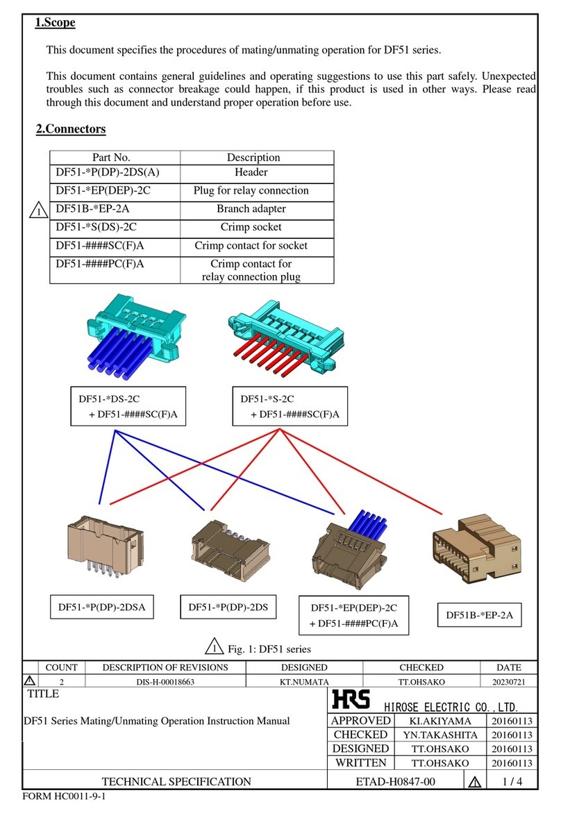
1. Scope
This document specifies the steps from crimping the DF63W-series crimped terminals to
cables (AWG16 to AWG22) to inserting the terminals to crimping sockets.
2. Connectors
Crimping cases
DF63W # –EP –3.96 C
❻


Crimped terminals
DF63(W) –1618 PCF

Name: DF63W
Wire seal
#=None or A 
No. of poles: 2 to 6
Connector types
S : Socket
EP: In-line plug
Contact pitch: 3.96 mm
❻Shape of connection
C: Crimping case
Name: DF63(W)
Compatible cables
1618: AWG16 to 18
2022: AWG20 to 22
Shape/packing
SCF : Socket terminal, reeled
SC : Socket terminal, separate
PCF : Plug terminal, reeled
PC : Plug terminal, separate
COUNT
DESCRIPTION OF REVISIONS
DESIGNED
CHECKED
DATE
2
3
DIS-H-00014188
HT.SATO
SZ.ONO
20220621
TITLE
DF63W Series CableAssembly Procedure
APPROVED
KI.AKIYAMA
20150525
CHECKED
HK.UMEHARA
20150525
DESIGNED
TO.HORII
20150525
WRITTEN
TO.HORII
20150525
TECHICAL SPECIFICATION
ETAD-H0814-00
2
1 / 6
FORM HC0011-9-1
HIROSE ELECTRIC CO.,LTD.
2
Jun.1.2022Copyright2022HIROSEELECTRICCO.,LTD.AllRightsReserved.
HIROSE ELECTRIC CO.,LTD.
ETAD-H0814-00
2
2 / 6
FORM HC0011-9-2
3. Steps for harnessing
3.1. Cable stripping
Strip cables in accordance with Crimping Quality Standards (ATAD-H0810/0811).
In so doing, make sure there is no scratch on cable cores.
3.2. Crimping
Crimped terminals to cables using an applicator (AP105-DF63-1618-*), and check the crimping
height and shape in accordance with the Table of crimping conditions and Crimping Quality
Standards (ETAD-H0810/0811).
3.3. Insertion to crimping terminal sockets
Hold the cable of a crimped terminal, and insert it to each terminal hole of crimping sockets.
(Insert the terminal in the direction of arrows below.)
*The figures show insertion to DF63W-4EP-3.96C and DF63W-4S-3.96C.
For insertion, place the crimped terminal and crimping socket lock in the following direction:
Before inserting terminal
After inserting terminal
Lanse holder
Lanse holder
Socket
Socket terminal
Plug terminal
In-line Plug
Lock :Upper
Lock :Upper
Contact No.
Contact No.
Lanse holder:
Lower
Lanse holder:
Lower
Direction of insertion
Jun.1.2022Copyright2022HIROSEELECTRICCO.,LTD.AllRightsReserved.
HIROSE ELECTRIC CO.,LTD.
ETAD-H0814-00
2
3 / 6
FORM HC0011-9-2
Insert the crimped terminal to pass through the hole of wire seal.
To maintain performance reliability, do not tilt crimped terminals for insertion.
Horizontal insertion 
Tilted insertion 
Hole of wire seal
Hole of wire seal
Jun.1.2022Copyright2022HIROSEELECTRICCO.,LTD.AllRightsReserved.
HIROSE ELECTRIC CO.,LTD.
ETAD-H0814-00
2
4 / 6
FORM HC0011-9-2
Check that the lance of a crimping socket has been caught at the lance holder of a crimped
terminal.
(Slightly pull the terminal to check.)
*To remove the crimped terminal halfway through insertion, pull the cable while pressing wire
seal to prevent coming off.
3.4. Repair of crimped terminal
To remove crimped terminals that have been inserted, pull the cable using the dedicated
Precision Screwdriver while pushing up the crimping socket lance.
Using crimping socket after repair could induce decrease of lance strength and / or wire seal
damage. Use new socket to avoid such failures.
Approx. over 30mm
In-line plug lance
Socket lance
Crimped terminal
Lance holder
In-line plug lance
Socket lance
Precision screwdriver
Approx. over 30mm
Jun.1.2022Copyright2022HIROSEELECTRICCO.,LTD.AllRightsReserved.
HIROSE ELECTRIC CO.,LTD.
ETAD-H0814-00
2
5 / 6
FORM HC0011-9-2
4. Precautions for handling
4.1. Packing and storage
To pack or store assemblies, make sure overlapped connectors will not apply extreme load to
the lack section.
If load is applied to the lock section under high temperature and humidity for a long period of
time, the lock section will be deformed which could lead poor fitting.
4.2. Loading to a connector
To pack or store assemblies, make sure overlapped connectors will not apply extreme load to
excessive external force applied to connectors could cause failure or damage. Therefore,
avoid forced insertion or removal, dropping impact, cable wiring (pull, twist) and such.
Note) Breaking strength of lock is approx. 50 N when connector is pulled in straight
direction. Please avoid excessive force is applied to the connector.
Note) Retention force is approx. 27 N / Pin. Please avoid excessive force is applied to
particular cable.
During cable wiring inside the machine, keep sufficient cable length for slack to avoid direct
stress is applied to the connector.
4.3. Rubber seal
If the rubber seal is damaged, the connector is deteriorated water resistant performance.
Therefore, do not use the connector whose rubber seal is damaged.
4.4. Wiring cable
When bundling cables, prepare a part that is straight from the end face of the connector as
shown in the figure below.
Do not bind near the end face of the connector because it will put a load on the terminal
contact part and the terminal crimping part and cause contact failure and waterproof
failure.
Keen bending,cable tension should be avoided
No cable tension is applied
2
Straight
2
Jun.1.2022Copyright2022HIROSEELECTRICCO.,LTD.AllRightsReserved.
HIROSE ELECTRIC CO.,LTD.
ETAD-H0814-00
2
6 / 6
FORM HC0011-9-2
4.5. Binding cable
During cable binding, keep approximately 30mm length from end of connector
to binding point.
If the length is short , it could cause loosing the contact by stress.
Approx. over 30mm
Approx. over 30mm
Binding
Jun.1.2022Copyright2022HIROSEELECTRICCO.,LTD.AllRightsReserved.

Other HRS Cables And Connectors manuals

HRS BM20 Series User manual

HRS

HRS BM20 Series User manual

HRS DF51 Series User manual

HRS

HRS DF51 Series User manual

HRS DF63 Series User manual

HRS

HRS DF63 Series User manual

HRS GT36A User manual

HRS

HRS GT36A User manual

HRS ZE05 Series User manual

HRS

HRS ZE05 Series User manual

HRS GT50 Series Instruction Manual

HRS

HRS GT50 Series Instruction Manual

HRS DF57 Series User manual

HRS

HRS DF57 Series User manual

HRS EM30MSD Series User manual

HRS

HRS EM30MSD Series User manual

HRS ZE064W Series User manual

HRS

HRS ZE064W Series User manual

HRS GT36 User manual

HRS

HRS GT36 User manual

HRS ZH05 Series User manual

HRS

HRS ZH05 Series User manual

HRS HIF Series User manual

HRS

HRS HIF Series User manual

HRS BM25 Series User manual

HRS

HRS BM25 Series User manual

HRS DF40 Series User manual

HRS

HRS DF40 Series User manual

HRS FH12-20S-0.5SH(54) User manual

HRS

HRS FH12-20S-0.5SH(54) User manual

HRS BNC75 Series Manual

HRS

HRS BNC75 Series Manual

HRS HELIX User manual

HRS

HRS HELIX User manual

HRS Hirose IT3 Quick start guide

HRS

HRS Hirose IT3 Quick start guide

HRS SignalBee DF13 Series User manual

HRS

HRS SignalBee DF13 Series User manual

HRS GT50 Series User manual

HRS

HRS GT50 Series User manual

HRS DF62W EP 2.2C Series User manual

HRS

HRS DF62W EP 2.2C Series User manual

HRS BM25 Series Instruction Manual

HRS

HRS BM25 Series Instruction Manual

HRS FH67 Series User manual

HRS

HRS FH67 Series User manual

HRS FH29 Series User manual

HRS

HRS FH29 Series User manual

Popular Cables And Connectors manuals by other brands

Integra MAYFIELD A1060 instruction manual

Integra

Integra MAYFIELD A1060 instruction manual

CommScope ETHERSEAL 1479563-2 instruction sheet

CommScope

CommScope ETHERSEAL 1479563-2 instruction sheet

Extron electronics M59-5 BNC/100 Specification sheet

Extron electronics

Extron electronics M59-5 BNC/100 Specification sheet

National Instruments IMAQ D100 installation guide

National Instruments

National Instruments IMAQ D100 installation guide

LAPP MODE3 2.0 operating instructions

LAPP

LAPP MODE3 2.0 operating instructions

Belden ELWIKA 5012 PG9 Assembly instructions

Belden

Belden ELWIKA 5012 PG9 Assembly instructions

Motorola RKN4136 quick start guide

Motorola

Motorola RKN4136 quick start guide

Sygonix 2632392 operating instructions

Sygonix

Sygonix 2632392 operating instructions

Insignia NS-SBNC100P92 Quick setup guide

Insignia

Insignia NS-SBNC100P92 Quick setup guide

MiLAN MIL-L100S user guide

MiLAN

MiLAN MIL-L100S user guide

id-Technik KS 25/36 Assembly instructions

id-Technik

id-Technik KS 25/36 Assembly instructions

Honeywell GSM-EXT Assembly Installation Guide

Honeywell

Honeywell GSM-EXT Assembly Installation Guide

eLANtix EX-P24U-0.5 instruction manual

eLANtix

eLANtix EX-P24U-0.5 instruction manual

Fujikura FSM-70S Help guide

Fujikura

Fujikura FSM-70S Help guide

Predator 58374 Owner's manual & safety instructions

Predator

Predator 58374 Owner's manual & safety instructions

thomann DS 2418 user manual

thomann

thomann DS 2418 user manual

Deutsch QC24-7501P Termination instructions

Deutsch

Deutsch QC24-7501P Termination instructions

Essential Audio Tools Current Spyder L user manual

Essential Audio Tools

Essential Audio Tools Current Spyder L user manual

manuals.online logo
manuals.online logoBrands
  • About & Mission
  • Contact us
  • Privacy Policy
  • Terms and Conditions

Copyright 2025 Manuals.Online. All Rights Reserved.