manuals.online logo
Brands
  1. Home
  2. •
  3. Brands
  4. •
  5. HRS
  6. •
  7. Cables And Connectors
  8. •
  9. HRS FH12 Series User manual

HRS FH12 Series User manual

Other HRS Cables And Connectors manuals
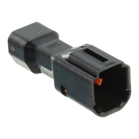
HRS ZE05 Series User manual

HRS

HRS ZE05 Series User manual

HRS DF57H S-1.2C Series User manual

HRS

HRS DF57H S-1.2C Series User manual

HRS FH67 Series User manual

HRS

HRS FH67 Series User manual

HRS HELIX User manual

HRS

HRS HELIX User manual

HRS BM25 Series Instruction Manual

HRS

HRS BM25 Series Instruction Manual

HRS DF63 Series User manual

HRS

HRS DF63 Series User manual

HRS GT50 Series User manual

HRS

HRS GT50 Series User manual

HRS DF51-6EP-2C User manual

HRS

HRS DF51-6EP-2C User manual

HRS DF62W EP 2.2C Series User manual

HRS

HRS DF62W EP 2.2C Series User manual

HRS FH29 Series User manual

HRS

HRS FH29 Series User manual

HRS GT36A User manual

HRS

HRS GT36A User manual

HRS DF63W Series Manual

HRS

HRS DF63W Series Manual

HRS HIF Series User manual

HRS

HRS HIF Series User manual

HRS BM25 Series User manual

HRS

HRS BM25 Series User manual

HRS EM30MSD Series User manual

HRS

HRS EM30MSD Series User manual
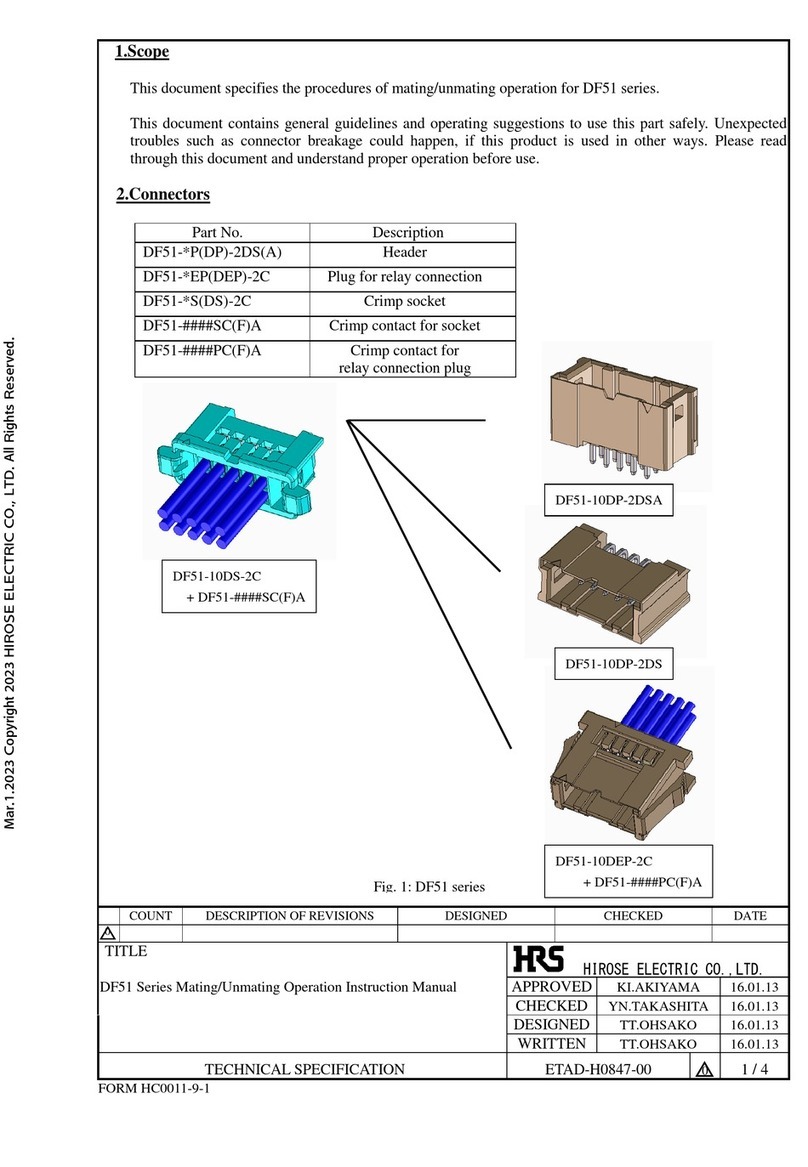
HRS Hirose IT3 Quick start guide

HRS

HRS Hirose IT3 Quick start guide

HRS FH12-20S-0.5SH(54) User manual

HRS

HRS FH12-20S-0.5SH(54) User manual

HRS DF51 Series User manual

HRS

HRS DF51 Series User manual
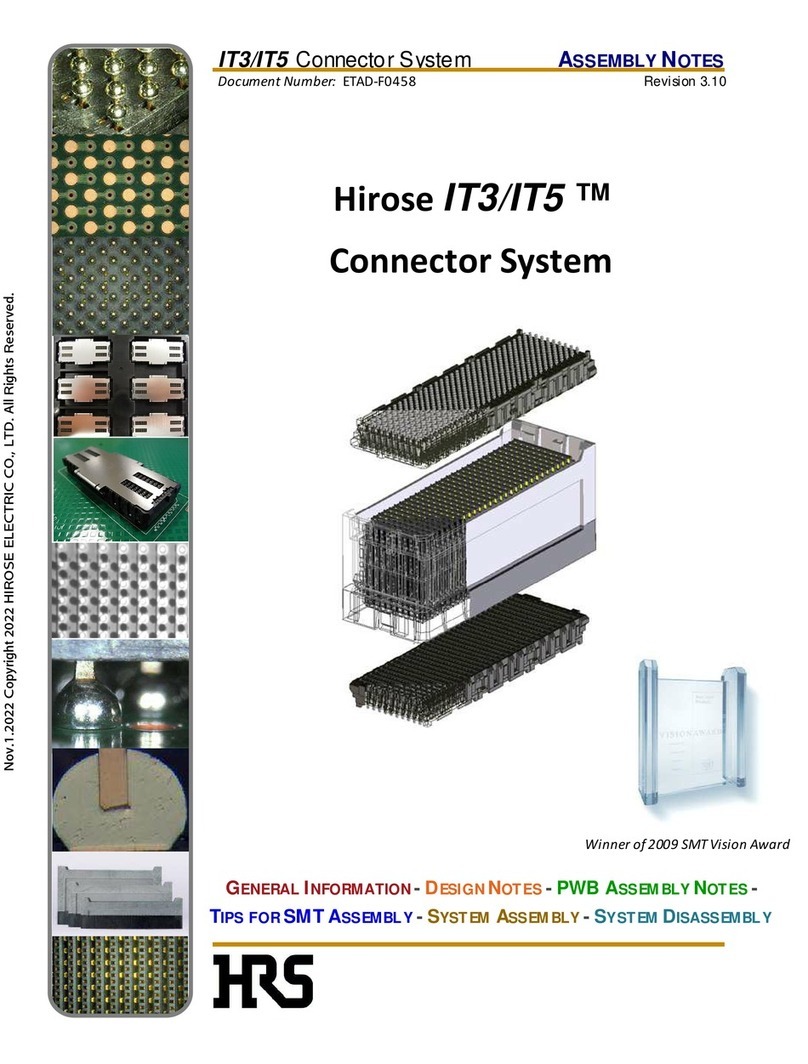
HRS DF57 Series User manual

HRS

HRS DF57 Series User manual

HRS DF62W Series User manual

HRS

HRS DF62W Series User manual

HRS BNC75 Series Manual

HRS

HRS BNC75 Series Manual

HRS BM20 Series User manual

HRS

HRS BM20 Series User manual
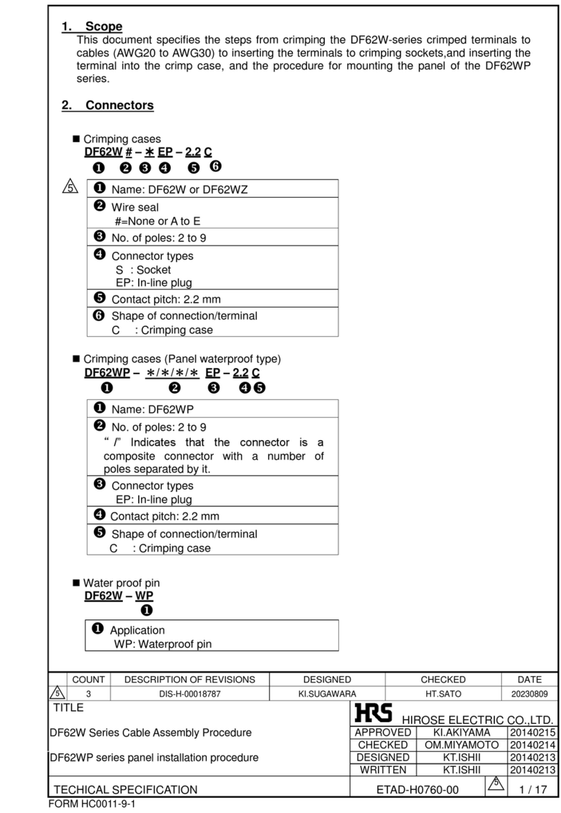
HRS ZE064W Series User manual

HRS

HRS ZE064W Series User manual

HRS GT36 User manual

HRS

HRS GT36 User manual

Popular Cables And Connectors manuals by other brands

StarTech.com ST124HD20 quick start guide

StarTech.com

StarTech.com ST124HD20 quick start guide

Philips SWV4543S/10 Features

Philips

Philips SWV4543S/10 Features

Larson Electronics 10-50C instruction manual

Larson Electronics

Larson Electronics 10-50C instruction manual

Grip MEK-PM Assembly and operating manual

Grip

Grip MEK-PM Assembly and operating manual

Ultra Products Travel Pack #3 ULT31436 Specifications

Ultra Products

Ultra Products Travel Pack #3 ULT31436 Specifications

Surpass QCH-F Operation manual

Surpass

Surpass QCH-F Operation manual

Philips SWA6310 Specifications

Philips

Philips SWA6310 Specifications

StarTech.com CRJ4550PK quick start guide

StarTech.com

StarTech.com CRJ4550PK quick start guide

Nohau EMUL-IP2K-PC user guide

Nohau

Nohau EMUL-IP2K-PC user guide

Foxun SX-SP144E-HD4K2K operating instructions

Foxun

Foxun SX-SP144E-HD4K2K operating instructions

Philips SWA3305W Specifications

Philips

Philips SWA3305W Specifications

opticis Stretch DVIM1-1P0x user manual

opticis

opticis Stretch DVIM1-1P0x user manual

Volkswagen VAS 6558A operating manual

Volkswagen

Volkswagen VAS 6558A operating manual

NEXIBO N-13 user manual

NEXIBO

NEXIBO N-13 user manual

CYP PU-1H3HBTL Operation manual

CYP

CYP PU-1H3HBTL Operation manual

Allen-Bradley 1784-u2dhp installation instructions

Allen-Bradley

Allen-Bradley 1784-u2dhp installation instructions

Global Caché Flex Link Blaster quick start

Global Caché

Global Caché Flex Link Blaster quick start

Hauppauge USB-Live2 Quick installation guide

Hauppauge

Hauppauge USB-Live2 Quick installation guide

manuals.online logo
manuals.online logoBrands
  • About & Mission
  • Contact us
  • Privacy Policy
  • Terms and Conditions

Copyright 2025 Manuals.Online. All Rights Reserved.

FH12 Series●0.5mm and 1mm Pitch Connectors For FPC/FFC
Operation Precautions
■Connector Operating Instructions, precautions and recommendations
●Bottom Contact Type (common for 0.5mm/1mm Pitch)
1. FPC/FFC Termination procedure.
Connector installed on the board.
1)
Lift up the actuator. Use thumb or index finger.
1) Avoid grasping the actuator with two fingers or
lifting the actuator with fingernail.
2) Do not use a thin tool such as the tip of a
screwdriver to release the lock lever. Doing so
will cause deformation of the contacts.
3)
Do not apply force in the direction of arrows A, B, or C
while the lock lever is open.
Doing so will cause the lock lever to become disen gaged,
or will damage the hook portion of the connector body.
4)
When inserting the FPC/FFC, do not forcefully rub against
the surface beneath the connector insertion slot.
Doing so will result in the FPC/FFC forcefully striking the
contacts and this will cause contact deformation, peeling
of the FPC/FFC conductors, and other irregularities.
5)
Insert the FPC/FFC at the proper position of the connector
insertion slot, and insert perpendicularly with respect to the con-
nector. Improper insertion will cause continuity problems, disen-
gagement of the lock lever, and damage to the hook portion.
2) Fully insert the FPC/FFC parallel to mounting
surface, with the exposed conductive traces
facing down.
17
FPC/FFC conductive traces
FH12 Series●0.5mm and 1mm Pitch Connectors For FPC/FFC
●Bottom Contact Type (common for 0.5mm/1mm Pitch)
Operation Precautions
3) Rotate down the actuator until firmly closed.
It is critical that the inserted FPC/FFC is not
moved and remains fully inserted. Should the
FPC/FFC be moved, open the actuator and
repeat the process, starting with Step 1.
2. FPC/FFC Removal
1) Lift up the actuator.
2) Carefully remove the FPC/FFC.
6)
Partial insertion of the FPC/FFC, offset insertion,
and diagonal insertion will result in an unfavor-
able engagement of the lock lever in which the
lock lever is raised. To correct this, first remove
the FPC/FFC and then reinsert it. Forcing the
lock will damage the connector.
7) When locking, handle the FPC/FFC so that a
load is not applied to the FPC/FFC as would
occur by pulling the FPC/FFC, or lifting it, etc.
When a load is applied in the opposite direc-
tion to the rotational movement of the lock, an
excessive load will be applied and this will
cause connector damage.
8) At the time of lock operation, application of
force such as that indicated by the arrows in
the diagrams below will cause the lock lever to
disengage. When the lock lever has become
disengaged, please exchange the entire con-
nector.
Stiffener
18
FH12 Series●0.5mm and 1mm Pitch Connectors For FPC/FFC
●Top Contact Type
Operation Precautions
1. FPC/FFC Termination procedure.
Connector installed on the board.
1)
Lift up the actuator. Use thumb or index finger.
2) Fully insert the FPC/FFC parallel to mounting
surface, with the exposed conductive traces
facing UP.
3) Rotate down the actuator until firmly closed.
It is critical that the inserted FPC/FFC is not
moved and remains fully inserted. Should the
FPC/FFC be moved, open the actuator and
repeat the process, starting with Step 1
above.
2. FPC/FFC Removal
1) Lift up the actuator.
2) Carefully remove the FPC/FFC.
FPC/FFC conductive traces
Stiffener
FPC insertion area
1)
Avoid further lifting of the actuator once the lock has
been released. Doing so will cause the lock lever to
separate from the rotational shaft, and the lock lever
will become disengaged or the hook portion of the
connector body will be damaged.
2)
Avoid further pressing of the lock portion from
the locked condition when the FPC/FFC has
not yet been inserted. Doing so will cause the
lock lever to become disengaged from the
rotational shaft, and the hook portion of the
connector body will be damaged.
3)
Do not insert the FPC/FFC diagonally. Doing
so will result in the corners of the FPC/FFC
catching on the contacts and will cause defor-
mation of the contacts.
4) When closing down the actuator apply equal
pressure to both sides of the actuator.
actuator
Rotational shaft
19
20 The contents of this catalog are current as of date of 11/2013. Contents are subject to change without notice for the purpose of improvements.
FH12 Series●0.5mm and 1mm Pitch Connectors For FPC/FFC
●Vertical Mounting type (common for 0.5 mm/1 mm pitch)
Operation Precautions
1. FPC/FFC Termination procedure.
Connector installed on the board.
1) Verify that the actuator is positioned upright.
If the actuator has rotated to the side, care-
fully rotate it upright.
2) Insert the FPC/FFC vertically in the connector
slot assuring that the conductive traces of the
FPC/FFC are facing away from the actuator.
1) Avoid forcing the actuator up or down without
the FPC/FFC inserted.
3)
Do not insert the FPC/FFC diagonally. Doing so
will result in the corners of the FPC/FFC catching
on the contacts and will cause deformation of the
contacts.
Actuator upright
FPC/FFC conductive traces
Stiffener
Slot
3)
Press down the actuator in the direction shown.
2. FPC/FFC Removal
Rotate the actuator upward and withdraw the FPC/FFC.
2)
Do not attempt to open or over rotate an already
released actuator (refer to the diagram below).
These actions may damage the actuator.
4)
Do not press down vertically on the actuator when
the FPC/FFC already inserted, it needs to be rotat-
ed to engage the lock. Refer to the diagram below.
Doing so may cause actuator failure.
6-3,Nakagawa Chuoh-2-Chome,Tsuzuki-Ku,Yokohama-Shi 224-8540,JAPAN
TEL: +81-45-620-3526 Fax: +81-45-591-3726
http://www.hirose.com
http://www.hirose-connectors.com
®