04/03 P/N 211953A
5
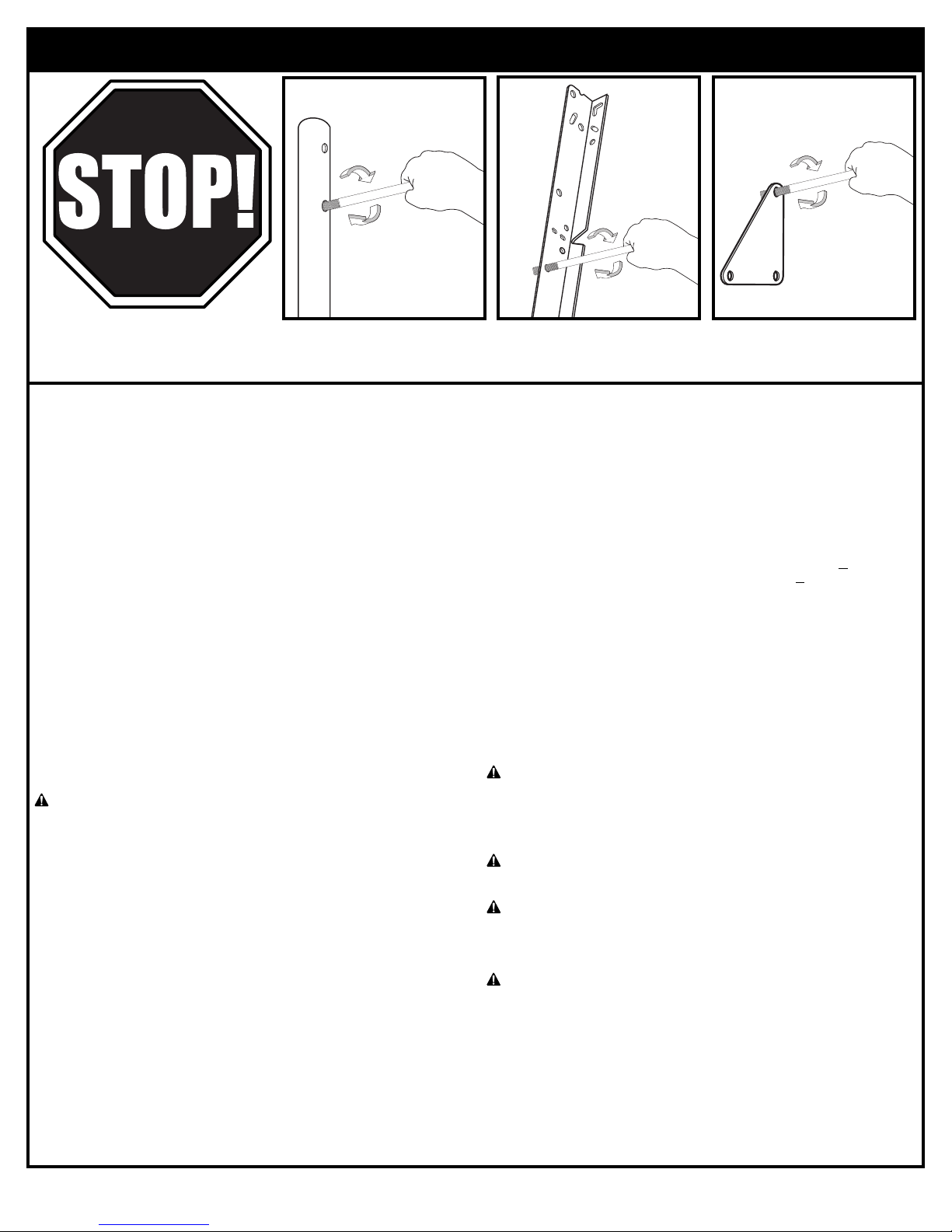
BEFORE YOU START!
To ensure opt mal playab l ty of backboard system, a close tolerance f t between the elevator components and
hardware s requ red. Test f t large bolts nto large holes of elevator tubes, backboard brackets and tr angle plates.
Carefully rock them n a c rcular mot on to ream out any excess pa nt from holes f necessary.
ENGLISH INSTRUCTIONS
IMPORTANT! WRITE MODEL NUMBER FROM BOX ONTO PAGE 1 OF
THIS OWNERS MANUAL
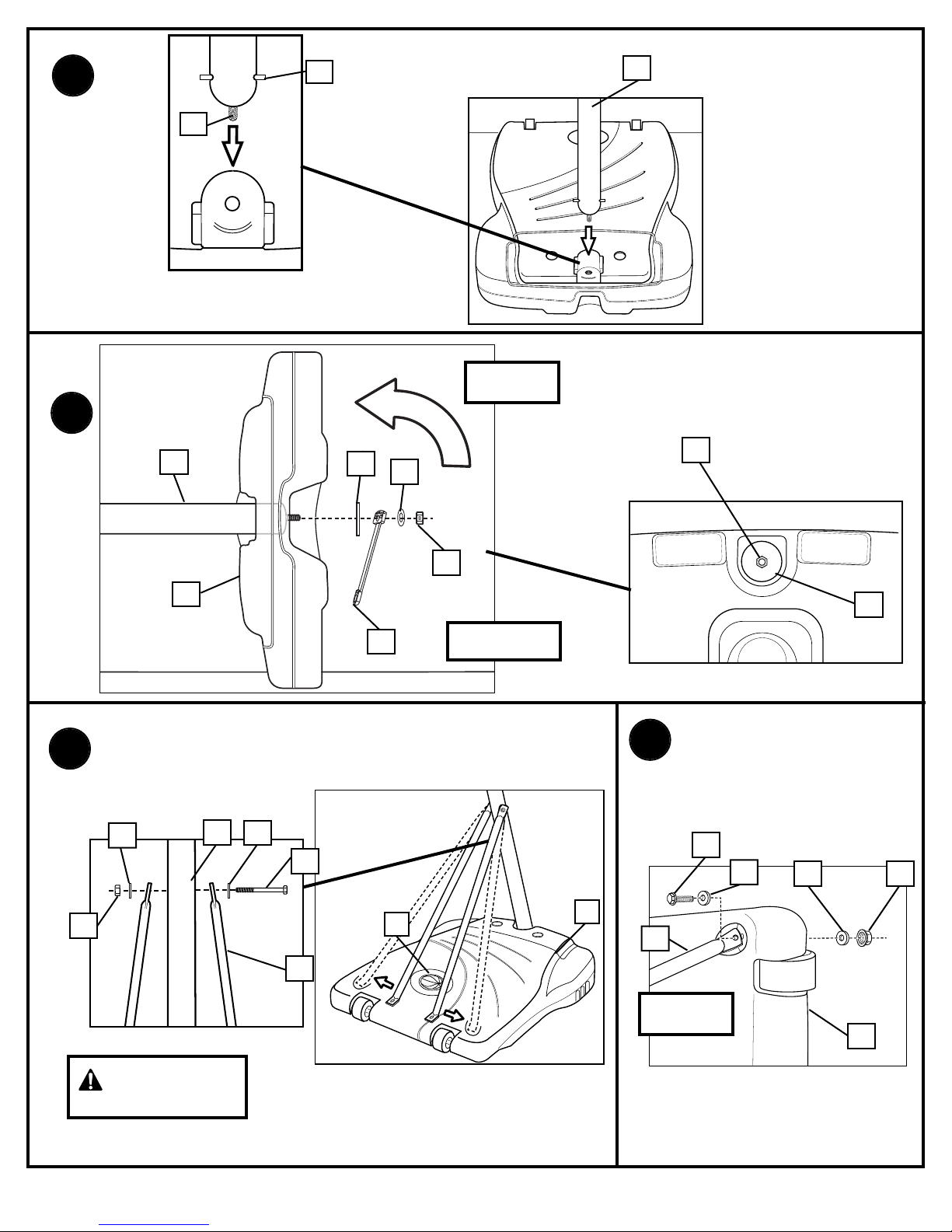
1. Remove all contents from underside of tank Keep tank (1) bottom side
up
2. Insert axle rod (2) through wheel (3), as shown Secure wheel assembly
to tank (1) by tapping wheel downward with hammer, snapping it into
position Repeat for opposite side, then carefully, turn tank (1) over
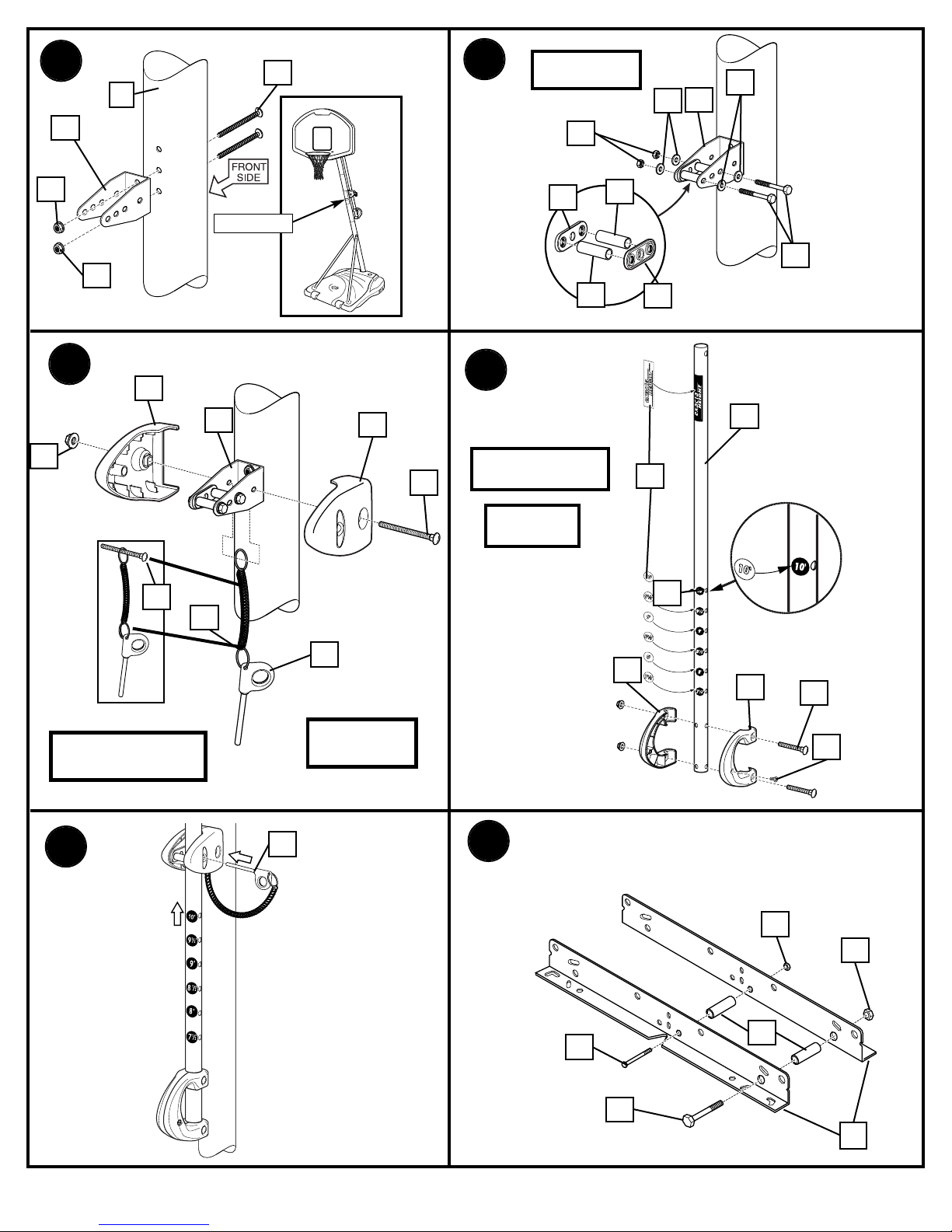
3. Mark pole sections with tape as shown
4. IMPORTANT! Center al gnment slot of m ddle pole sect on (5) n a
lower hole of top pole sect on (4) as shown. While maintaining
alignment, bounce pole top (4) and middle section (5) together as shown
until they no longer move toward taped reference mark Upright
assembly NOTE: Pole sections should have a
3-1/2” (9 cm) minimum overlap
5. IMPORTANT! Center al gnment slot of lower pole sect on (6) n a
lower hole of m ddle pole sect on (5) as n step 4. While maintaining
alignment, bounce assembly and lower section (6) together as shown
until they no longer move toward taped reference mark NOTE: Pole
sections should have a 3-1/2” (9 cm) minimum overlap
6. Install rod (7) through holes in bottom pole section (6) and eyebolt (8)
7. Insert pole assembly into tank assembly as shown
8. Carefully place unit on its side Secure pole bottom (6) to tank with
anchor strap (52), washers (9 & 13) and nut (10) as shown Upright unit
NOTE: Keep unnecessary pressure off of the pole assembly when in this
position Two people recommended for this procedure IMPORTANT!
Do not over t ghten, w ll crack tank.
9. Secure strut tubes (11) to bottom pole section (6) as shown
WARNING: TIGHTEN BOLT (14) IN LOCKNUT (12) UNTIL FLUSH
(EVEN) WITH LOCKNUT’S OUTER EDGE.
10. Once again, carefully place unit in the side position and secure strut (11)
to tank (1) as shown Completely tighten Repeat for opposite side
Upright unit NOTE: Keep unnecessary pressure off of the pole assembly
when in this position Two people recommended for this procedure
11. Install pole mount (17) bracket with carriage bolts (18) as shown Tighten
flange nuts (16) completely
12. Attach spacers (22, 23) to pole mount bracket (17) with bolts (21),
washers (19), and nuts (20) as shown IMPORTANT! T ghten unt l
washers (19) no longer move.
13. Attach covers (24) onto pole mount bracket (17) with carriage bolt (25)
and nut (16) as shown
IMPORTANT: Loop end of p n lanyard (27) over carr age bolt (25)
dur ng th s assembly. NOTE: Assemble lanyard (27) to locking pin (26)
as shown
14. Apply logo and height indicator labels (29) to adjustment rod (28) as
shown Attach handle parts (32, 33) to adjustment rod with screw (31),
carriage bolt (30), and flange nut (16) as shown IMPORTANT:
Ind cator labels should be appl ed as close to holes as poss ble to
prevent labels from be ng damaged dur ng he ght adjustment.
NOTE: Holes in adjustment rod allow for either rear access or side
access
15. Insert handle assembly through pole mount assembly as shown Lock
pole assembly in place at the 10’ (3 05 m) mark with pin (26)
16. Install spacers (36) onto backboard brackets (34) with bolts (37, 21) and
lock-nuts (35, 20) as shown
17. Assemble lower elevator tubes (40) as shown
IMPORTANT! It s necessary for all parts to be nstalled for th s
mechan sm to work safely and properly. NOTE: Test fit bolts into
holes of brackets (34) and carefully rock them in a circular motion to
ream out paint from holes if necessary
18. Starting with nuts (16) flush against bracket (34), secure rim (42) and
bracket to backboard IMPORTANT! For spr ng loaded r m assembly,
refer to nstruct ons ncluded w th r m hardware. NOTE A: Do not
use washers here on spring return style rim NOTE B: Mounting nuts and
bolts supplied with rim hardware
19. Bend bracket (34) to line up with holes in backboard and secure
20. Assemble upper elevator tubes (43) to backboard brackets (34)
21. Support pole on sawhorse Attach backboard assembly to top pole
section (4) as shown Then install pole cap (46) NOTE: Two people are
recommended for this step Use caution; elevator assembly is heavy
22. Install upper elevator tubes (43) to triangle plates (45) as shown
23. Install handle assembly to lower elevator tubes (40) using bolt (47),
spacers (38, 55), and nut (39) as shown NOTE: Before going on to next
step, set adjustable system assembly to the 10’ (3 05 m) setting
24. Insert bolt (47) through left side upper elevator tube (43), then stretch
spring (41) onto bolt (47) Insert bolt (47) through right side upper
elevator tube (43) and secure with nut (39)
WARNING: USE EYE PROTECTION WHEN INSTALLING SPRINGS.
25. Roll completed assembly to desired playing area Secure assembly to
ground using anchor strap (52) and tie down stake (53) Fill tank with
water (approx 30 gallons (115 Liters)) or sand (approx 255 lbs (113 kg))
and snap cap (49) in place IMPORTANT! Add two gallons (7.6 L ters)
of non-tox c ant freeze n sub-freez ng cl mates.
WARNING: DO NOT LEAVE ASSEMBLY UNATTENDED WHEN
EMPTY, MAY TIP OVER.
26. While holding handle, remove pin (26)
WARNING: DO NOT ALLOW CHILDREN TO ADJUST HEIGHT.
27. Move elevator up or down to desired height
28. Replace pin (26) full length to lock system at desired height
29. Apply height and transport label (54) to front of pole as shown
Regulation rim height is 10 feet (3 05m)
WARNING: USE OF THIS PRODUCT WITHOUT PROPER
INSTALLATION OF SMART CLIPS, OR WHEN ALL SMART CLIPS
ARE NOT PRESENT COULD RESULT IN BODILY HARM. BE SURE
TO FOLLOW DIRECTIONS CAREFULLY.
30. Install net clips as shown (See illustration)
31. Install net as shown (See illustration)