6
STEP 1
Disassemble Clamp
• Remove the two screws (fig. B) using 4 mm hex key (fig. D) and detach
the smaller clamp bracket (fig. C) from the larger bracket
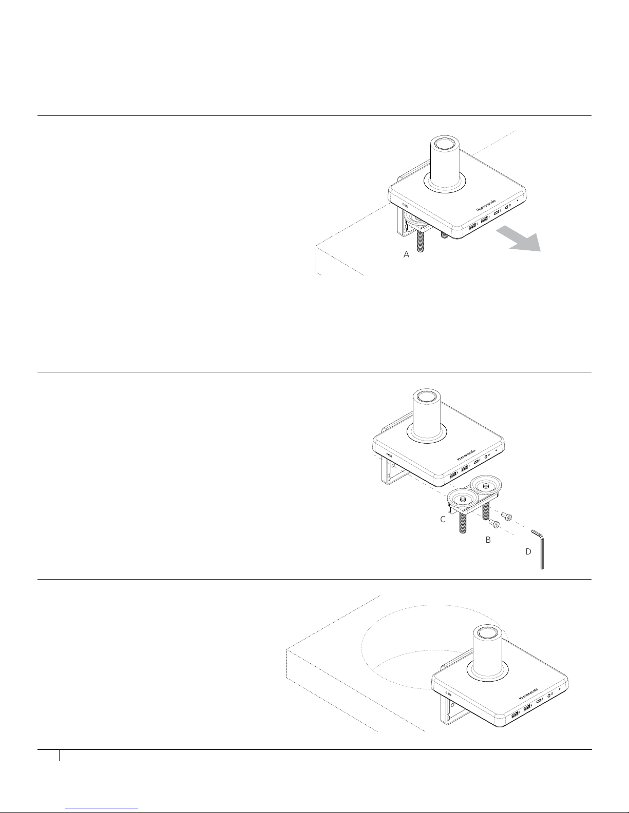
INSTALLING M/POWER ONTO EDGE OF TABLE
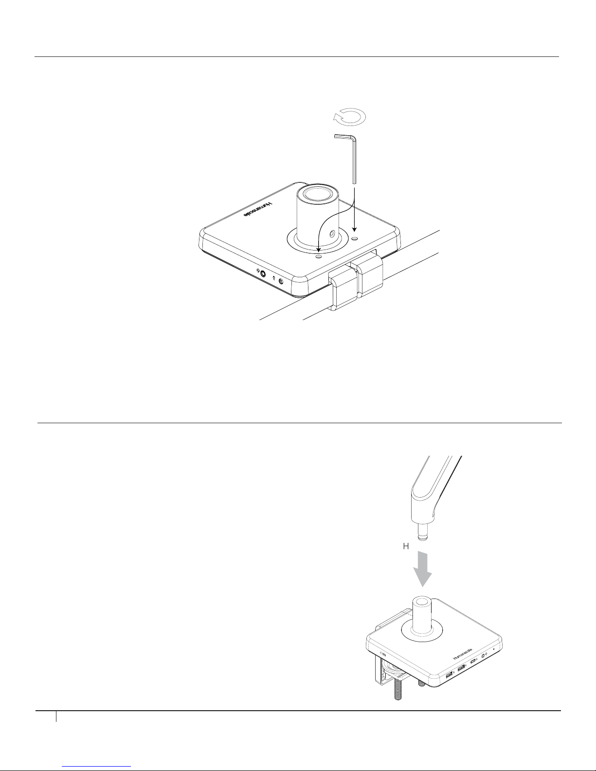
STEP 1
Place M/Power Clamp onto Table
• Slide mount against work surface edge and
fully tighten clamp screw (fig. A)
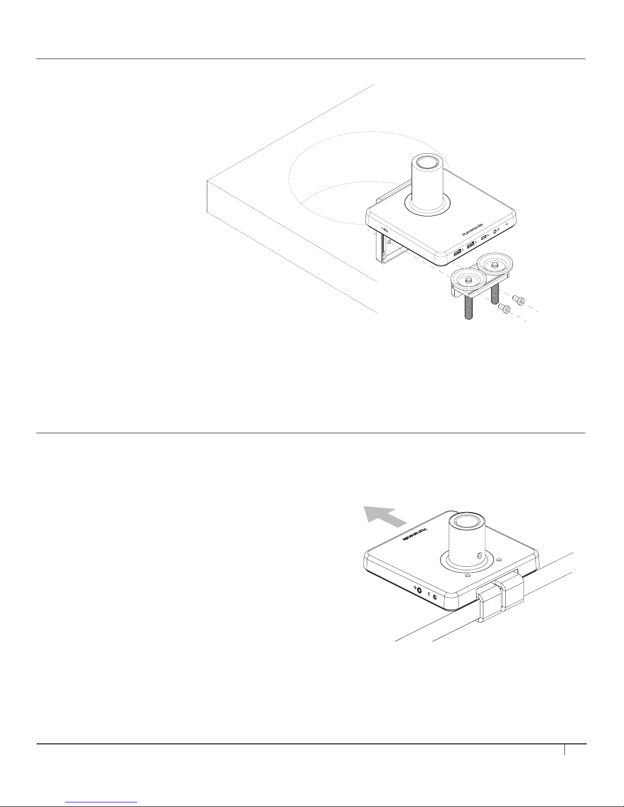
INSTALLING M/POWER THROUGH
A GROMMET HOLE OR SYSTEM FURNITURE
STEP 2
Place into Grommet Hole or System Furniture Gap
• Place the L Bracket of the M/Power through
the grommet hole and to the desired position
Note: Minimum hole diameter is 3" (76 mm)
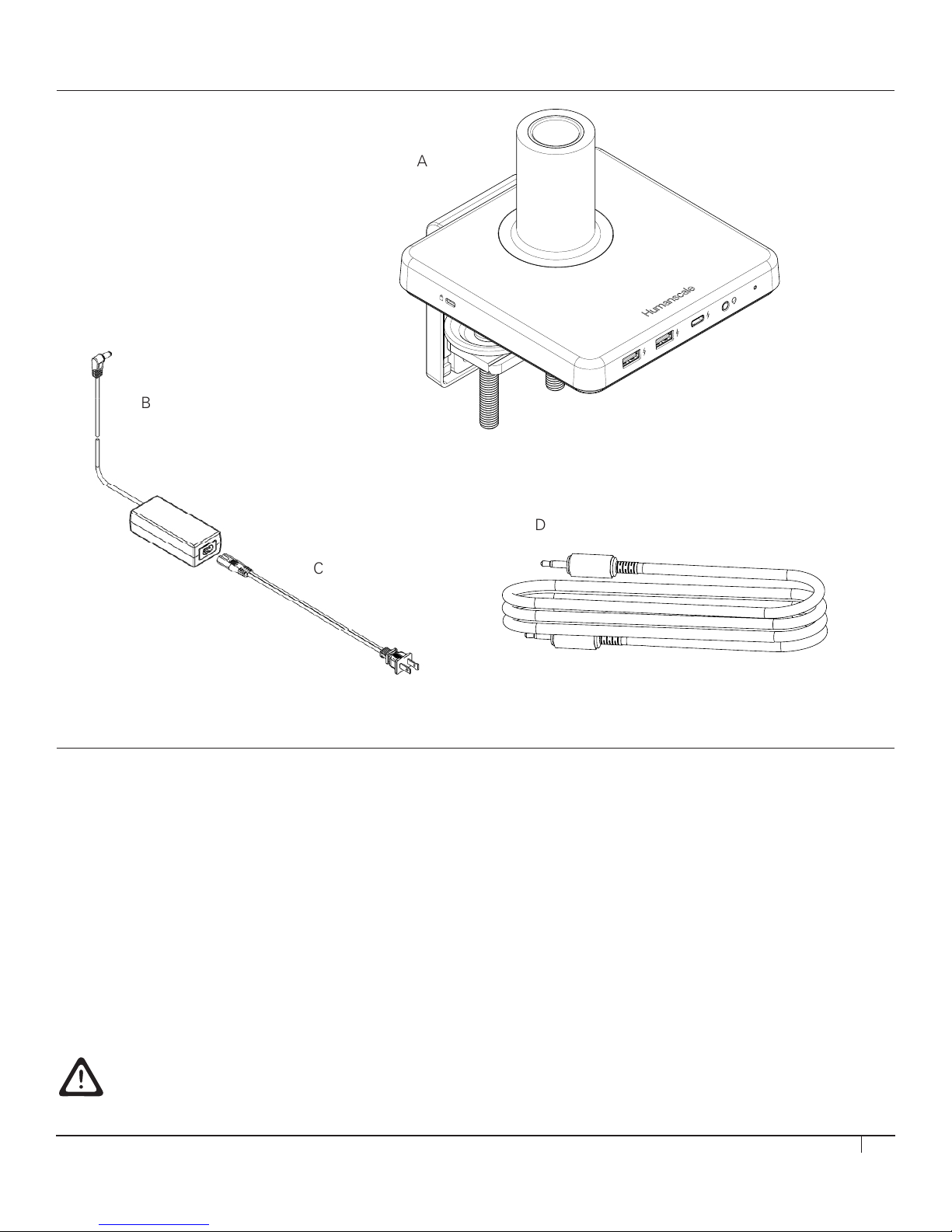
Caution: Maximum weight load of M/Power is as follows: M2.1: 15.5 lbs. M8.1: 28 lbs. M10: 40 lbs. M/Flex: 60 lbs. Total.
M10 is not to be used on M/Flex when mounted to M/Power
Do NOT exceed maximum weight limits.
When used in conjunction with M/Power, M/Flex post must be limited to 24 inches
6
STEP 1
Disassemble Clamp
• Remove the two screws (g. B) using 4mm hex key (g. D) and detach
the smaller clamp bracket (g. C) from the larger bracket
STEP 1
Place M/Power Clamp onto Table
• Slide mount against work surface edge and
fully tighten clamp screw (g. A)
INSTALLING M/POWER ONTO EDGE OF TABLE
INSTALLING M/POWER THROUGH A GROMMET HOLE
OR SYSTEM FURNITURE
STEP 2
Place into Grommet Hole or System Furniture Gap
• Place the L Bracket of the M/Power through
the grommet hole and to the desired position
Note: Minimum hole diameter is 3" (76 mm)
Caution: Maximum weightload of M/Power is as follows: M2: 20 lbs
M8: 40 lbs.
Do NOT exceed maximum weightload limits.
C
B
D
A