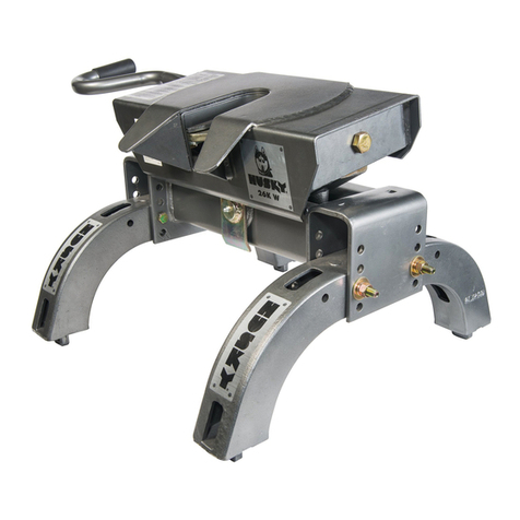
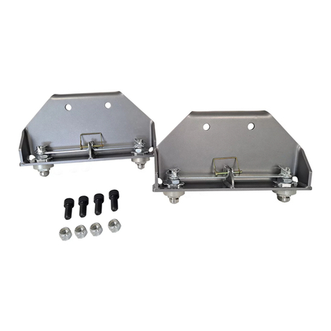
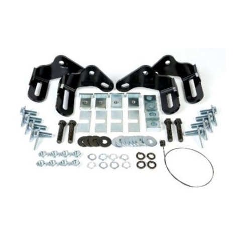
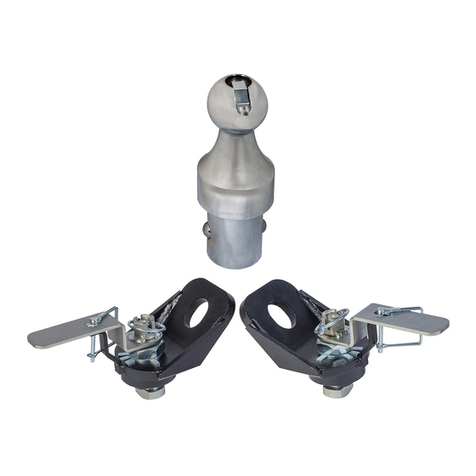
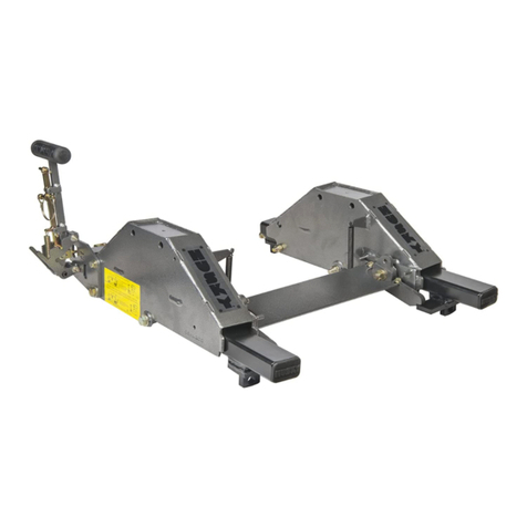
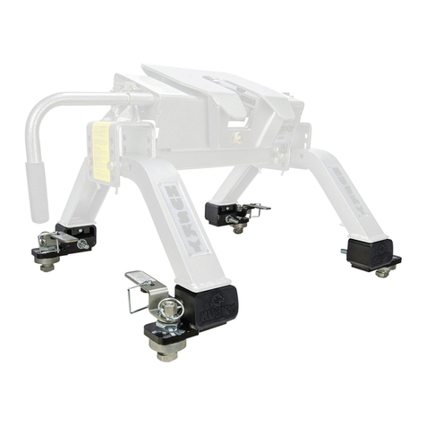
Husky 33310 User manual

All Products limited to Vehicle Tow Rating, see Vehicle Owners Manual. Visit www.huskytow.com for Warranty Information / Tech Support /
Product Updates. 2023 Keystone Automotive Operations Inc. All Rights Reserved. 2023-Rev4 Page-1
Assembly, Installation, Operation and
Maintenance Instructions
CENTER LINE FS SYSTEM
33310: CENTER LINE FS, 400-600 LBS. W/2-5/16” BALL
33311: CENTER LINE FS, 600-800 LBS. W/2-5/16” BALL
33312: CENTER LINE FS, 800-1200 LBS. W/2-5/16” BALL
INSTALL TIME:
0.5-1 HOUR
Dealer / Installer: Provide a copy of these instructions to the end user of this product. These
instructions provide important operating and safety information for proper usage
of this product. Demonstrate the proper use of the product with the end user.
Have the end user demonstrate that they understand the proper use of the
product.
End User: Read and follow all instructions included in this manual. Ask your Dealer / Installer
for assistance if you do not understand the proper use of the product. Never
remove any decals from the product. Failure to follow these instructions can result
in injury or death.
WARNING
DO NOT EXCEED RECOMMENDED TOWING LIMITS. SEE VEHICLE’S OWNER’S
MANUAL.
Rating when used as a weight distribution hitch with spring bars
CAUTION: The tongue weight rating of spring bars represents the capacity of a pair of bars,
NOT an individual bar
Part Number Max. Tongue Weight Max. Gross Trailer Weight
33310, 33311, & 33312 600 lbs. / 272 kg. 6,000 lbs. / 2721 kg.
Always use a pair of spring bars and be sure they are of the same weight rating and size for your trailer.
READ ALL INSTRUCTIONS AND CHECK PACKAGE CONTENTS BEFORE BEGINNING INSTALLATION.
Note: This system can be used on any angle tongue trailer.
Part Number Max. Tongue Weight Max. Gross Trailer Weight
33310 400-600 lbs. / 181-272 kg. 6,000 lbs. / 2721 kg.
33311 600-800 lbs. / 272-363 kg. 8,000 lbs. / 3629 kg.
33312 800-1200 lbs. / 363-544 kg. 12,000 lbs. / 5443 kg.
WARNING
Use ONLY with 4”, 5”, 6”, 7” & 8” trailer frames.
WARNING
Rating when used as a weight carrying hitch without spring bars

All Products limited to Vehicle Tow Rating, see Vehicle Owners Manual. Visit www.huskytow.com for Warranty Information / Tech Support /
Product Updates. 2023 Keystone Automotive Operations Inc. All Rights Reserved. 2023-Rev4 Page-2
Tools Required for Installation
The following list of tools will be needed for proper installation of all components:
•Safety Glasses
•15/16" Open End Wrench (5/8” HEX NUT)
•1-1/8” Box End Wrench (3/4” HEX HEAD BOLTS)
•1-1/16” Socket (3/4” HEX NUTS)
•3/4” Socket (1/2” HEX NUTS)
•½” Ratchet
•Measuring Tape
•Torque Wrench capable of 380 ft-lbs. of torque
•1-7/8” Thin-Walled Socket (1-1/4” HITCH BALL NUT) – REQUIRED ONLY IF REMOVING OR
TIGHTENING THE HITCH BALL
Recommended tools for installing the Hitch Ball:
None are required as the hitch ball comes from the factory pre-installed. It is recommended that you
check the torque of the hitch ball nut periodically using a 1-7/8” Thin-walled socket depending on hitch
ball size.
Torque Wrench capable of 380 ft-lbs. of torque (always check ball manufacturer’s specifications for
proper torque rating)
Important!
Before installing or towing with this Bolt Together Weight Distributing Hitch please read and
follow all instructions and warnings in the tow vehicle owner’s manual and trailer owner's
manual.
Have gross trailer weight and tongue weight checked before selecting and installing any weight
distributing system.
Weigh trailer again after fully loading and check loaded tongue and gross weight to ensure
proper weight distribution hitch is being used.
These instructions are guidelines only. Actual installation is the responsibility of the installer and the
owner. Always measure truck and trailer before installing hitch to be sure that there is clearance at the
bumper to allow for turns.
This kit is to ONLY be used with Husky weight distribution spring bars only that are designed for
this particular system. Do not substitute with any other spring bars.
Do not use a separate friction sway control on this unit!
WARNING
WARNING
WARNING

All Products limited to Vehicle Tow Rating, see Vehicle Owners Manual. Visit www.huskytow.com for Warranty Information / Tech Support /
Product Updates. 2023 Keystone Automotive Operations Inc. All Rights Reserved. 2023-Rev4 Page-3
Measure Trailer Coupler & Frame Height
NOTE: Changing the weight of the trailer and/or tow vehicle by adding, moving or unloading cargo
may require the need to adjust how the weight distribution system is set up.
IMPORTANT! Set parking brake of tow vehicle and chock the wheels of the trailer before lifting or
lowering!
1. Line up the tow vehicle and trailer on level pavement, in a straight position.
2. Use the trailer tongue jack to level the trailer. Measure the distance from pavement to the inside of
the coupler socket, and record here:_______________
3. Mark a spot on the side of the frame on the trailer as close to the coupler as you can. Measure from
this mark to the pavement, and record here: ______________. This measurement will be used later
to determine if a proper setup has been achieved.

All Products limited to Vehicle Tow Rating, see Vehicle Owners Manual. Visit www.huskytow.com for Warranty Information / Tech Support /
Product Updates. 2023 Keystone Automotive Operations Inc. All Rights Reserved. 2023-Rev4 Page-4
Measure the Tow Vehicle
For vehicles with air springs, air shocks or automatic leveling systems only: Check vehicle owner's
manual or other instructions on these items. Unless otherwise indicated, air springs and air shocks
should be deflated to their minimum recommended pressure BEFORE assembling and adjusting the
weight distribution hitch. Pick reference points at the top center of the front and rear fender well of
towing vehicle. Measure and record the height to pavement here:
FRONT FENDER TO PAVEMENT:
REAR FENDER TO PAVEMENT:
ILLUSTRATION 3
Installation and Setup
NOTE: To obtain proper ball height on low ground clearance tow vehicles, shank may be oriented in the
“UPRIGHT POSTION” as shown in Illustration 4. If shank is used in the “INVERTED POSITION, check
shank for adequate ground clearance. Accessory shanks with greater height and length are available
from your dealer. IMPORTANT! Proper adjustment requires the use of the proper length shank
and proper head height.
ILLUSTRATION 4

All Products limited to Vehicle Tow Rating, see Vehicle Owners Manual. Visit www.huskytow.com for Warranty Information / Tech Support /
Product Updates. 2023 Keystone Automotive Operations Inc. All Rights Reserved. 2023-Rev4 Page-5
4. Un-screw the 5/8-11 hex bolt until the bottom of the bolt threads are flush to the inside of the
channel.
5. Insert the shank into the receiver box. Hold the Center Line FS head assembly on the shank as
shown and align so that the hitch ball is 1" above the coupler socket.
5/8-11 HEX HEAD BOLT
ILLUSTRATION 5
ILLUSTRATION 6
In this example, the shank is
mounted in the Upright Position (as
shown). And the bottom 3/4” hex bolt
will pass through the 2nd hole from the
bottom on the shank. If needed, the
shank can be in the Inverted Position
(see page 4) to achieve the proper ball
height.
Shank in Upright Position

All Products limited to Vehicle Tow Rating, see Vehicle Owners Manual. Visit www.huskytow.com for Warranty Information / Tech Support /
Product Updates. 2023 Keystone Automotive Operations Inc. All Rights Reserved. 2023-Rev4 Page-6
6. Align the bottom hole on the channel to the hole on the shank. Place a ¾” washer onto the ¾” hex
bolt. Then insert the bolt with washer through the bottom hole in the channel and through the
shank. Remember the hole and orientation in these instructions are an example only, yours
may be different.
7. Place a ¾” washer onto the other ¾” hex bolt, then insert the bolt through the top hole in the
channel and through the shank.
ILLUSTRATION 8
ILLUSTRATION 7
¾” Washer and ¾” Hex Bolt

All Products limited to Vehicle Tow Rating, see Vehicle Owners Manual. Visit www.huskytow.com for Warranty Information / Tech Support /
Product Updates. 2023 Keystone Automotive Operations Inc. All Rights Reserved. 2023-Rev4 Page-7
8. The use of shims may be required to fill up the gap between the U channel and the shank. It
is NOT necessary to have equal shims on either side.
9. Tighten 5/8” hex bolt securely. Torque the 5/8” bolt to 50ft.lbs. Then, securely tighten the 5/8” jam
nut.
5/8” hex jam nut & Washer
5/8” hex bolt
U channel
Shim
ILLUSTRATION 9
ILLUSTRATION 10

All Products limited to Vehicle Tow Rating, see Vehicle Owners Manual. Visit www.huskytow.com for Warranty Information / Tech Support /
Product Updates. 2023 Keystone Automotive Operations Inc. All Rights Reserved. 2023-Rev4 Page-8
10. Put a ¾” flat washer on the top ¾” hex bolt followed by a ¾” nylon lock nut. Put a ¾” flat
washer on the bottom 3/4” hex bolt followed by a ¾” nylon lock nut. Torque the ¾” nylon
lock nuts to 260 ft-lbs.
11.Insert a spring bar into the tube. Secure with the “D”-pin. Swing wire “D” around the tube
and over the end of the pin. Repeat for the other side.
BE SURE THAT THE “D” RETAINING PIN GOES THROUGH GROOVE IN THE SPRING
BAR. PULL DOWN ON SPRING BARS TO TEST FOR PROPER ATTACHMENT.
¾ Nylon Lock Nut
¾ Flat Washer
Spring Bar
“D”-Pin
ILLUSTRATION 11
ILLUSTRATION 12

All Products limited to Vehicle Tow Rating, see Vehicle Owners Manual. Visit www.huskytow.com for Warranty Information / Tech Support /
Product Updates. 2023 Keystone Automotive Operations Inc. All Rights Reserved. 2023-Rev4 Page-9
12. Your Center Line FS system should look like this now.
Installing Frame Brackets
13. Remove L-Pin, tether, and hair pin from the lift bracket. Remove the 1/2” hex flange bolts so the
lift bracket can be removed from the frame bracket.
½” Hex Flange Bolts
Lift Bracket
Frame Bracket
Tether
L-Pin
Hair Pin
ILLUSTRATION 13
ILLUSTRATION 14

All Products limited to Vehicle Tow Rating, see Vehicle Owners Manual. Visit www.huskytow.com for Warranty Information / Tech Support /
Product Updates. 2023 Keystone Automotive Operations Inc. All Rights Reserved. 2023-Rev4 Page-10
28.5” – 30.5”
14. Install both frame brackets and frame plates 28.5”-30.5” away from the center of ball socket on
coupler on each side of the trailer frame. See Step 15 for frame bracket and plate assembly.
Frame brackets mount on the outside of the frame. Frame plates mount to inside of the frame.
15. Use the 1/2" carriage bolt, flat washer, lock washer and hex nut to hold the frame brackets in place
using the top hole. Use the 1/2" carriage bolt, flat washer, flat washer with tether, lock washer and
hex nut to hold the frame brackets and frame plates in place through the hole closest to the
underside of the trailer frame. Tighten all (4) 1/2" carriage bolts to 45-55 ft. - lbs.
½” FLAT WASHER
½” HEX NUT
½” LOCK WASHER
FLAT WASHER WITH
TETHER BETWEEN LOCK
WASHER AND FLAT
WASHER
INSIDE VIEW OF
FRAME BRACKET
ASSEMBLY
OUTSIDE VIEW OF
FRAME BRACKET
ASSEMBLY
TOP BOLT ASSEMBLY
WITHOUT TETHER
BOTTOM BOLT
ASSEMBLY
WITH TETHER
CARRIAGE
BOLT
TRAILER FRAME
FRAME BRACKET
FRAME BRACKET
FRAME PLATE
ILLUSTRATION 15
ILLUSTRATION 16

All Products limited to Vehicle Tow Rating, see Vehicle Owners Manual. Visit www.huskytow.com for Warranty Information / Tech Support /
Product Updates. 2023 Keystone Automotive Operations Inc. All Rights Reserved. 2023-Rev4 Page-11
16. Install the lift bracket by adjusting the height of the lift bracket so that the measured distance from
the ground to the spring bar support surface is (approximately) 3-1/2” from the top tip of the spring
bar. (Dimension “A” = Dimension “B” +3-1/2”). This is a starting point, and you may need to make
adjustments later. Install the ½” hex head flange bolts. Using a 3/4” socket and tighten the ½” hex
head flange bolts to 75 ft.-lbs.
17. Back up the tow vehicle and align the hitch ball so that it is directly under the coupler socket
(use a spotter if you have one. CAUTION! Spotter should never stand between trailer and tow
vehicle during connecting). Then, lower the trailer until the hitch is supporting some of the trailer
tongue weight. The tow vehicle and trailer must be as straight and inline as possible.
18. Ensure the hitch ball is completely inside the coupler socket and close the coupler ball latch if it is
not yet closed. Install coupler lock or pin for safety.
19. Raise the front of the trailer and rear of the tow vehicle until the tips of the spring bars are about
level / even with the support surface of the loading brackets.
Attaching Trailer to Ball
Make sure the wheels on the trailer are chocked before connecting coupler to ball.
IMPORTANT! Ensure the tow vehicle and trailer are on level ground and in-line with each other.
Set parking brake of tow vehicle and chock the wheels of the trailer before lifting or lowering!
GROUND/PAVEMENT
DIMENSION “A”
1”+ APPROX.
SPRING BAR
SUPPORT SURFACE
3-1/2” APPROX.
DIMENSION “B”
LIFT BRACKET
1/2” hex head
flange bolts
ILLUSTRATION 17

All Products limited to Vehicle Tow Rating, see Vehicle Owners Manual. Visit www.huskytow.com for Warranty Information / Tech Support /
Product Updates. 2023 Keystone Automotive Operations Inc. All Rights Reserved. 2023-Rev4 Page-12
Lift Tool Assembly
20. Insert lift bar into lift tool.
21. Insert M6 X 30mm hex head bolts into holes through handle assembly.
22. Place M6 flat washer onto hex bolts.
23. Place M6 lock washer onto M6 X 30 hex bolts.
24. Thread M6 hex nuts onto M6 X 30 hex bolts and finger tighten.
25. Tighten hex nuts until lock washer is flattened.
DO NOT OVER TIGHTEN OR USE AN IMPACT GUN.
ILLUSTRATION 18

All Products limited to Vehicle Tow Rating, see Vehicle Owners Manual. Visit www.huskytow.com for Warranty Information / Tech Support /
Product Updates. 2023 Keystone Automotive Operations Inc. All Rights Reserved. 2023-Rev4 Page-13
Spring bar loading on lift brackets
27. To load the spring bar onto the lift bracket, orient the lift tool as shown below and come under the
spring bar. Then, put the “finger” of the lift tool into the square hole on the lift bracket and using
BOTH hands on the lift tool. Lift firmly and then rotate and push the lift tool towards the trailer
until the spring bar is resting completely on the lift bracket and off the 2 pins. If it is too difficult
to lift the spring bar, then raise the height of the trailer until the spring bar is closer to the spring
bar support surface of the lift bracket.
ILLUSTRATION 19

All Products limited to Vehicle Tow Rating, see Vehicle Owners Manual. Visit www.huskytow.com for Warranty Information / Tech Support /
Product Updates. 2023 Keystone Automotive Operations Inc. All Rights Reserved. 2023-Rev4 Page-14
28. Once the spring bar is resting securely on the lift bracket insert the “L” retaining pin into the
square hole and secure with the hair pin clip.
Check Vehicle Height and Adjust Spring Bars If Necessary
29. Retract the tongue jack completely so the hitch is supporting the weight of the trailer.
Measure the same 3 places as done on pages 3 & 4 and compare. The tow vehicle should
settle evenly front to back. The rear fender should not settle lower than the front fender, if it has
then you will need to raise the lift brackets 1 hole. The frame mark should be ¼”-1” max higher
than the original measurement noted on page 3.
Keep clear of the pivot path of all moving parts when there is tension on the spring bar. Maintain control of
the lift tool at all times when raising or lowering the spring bar. Be sure that the “L” pin and hair pin is in
place before driving.
WARNING
ILLUSTRATION 20

All Products limited to Vehicle Tow Rating, see Vehicle Owners Manual. Visit www.huskytow.com for Warranty Information / Tech Support /
Product Updates. 2023 Keystone Automotive Operations Inc. All Rights Reserved. 2023-Rev4 Page-15
Properly Adjusted System
Over Adjusted System
Under Adjusted System
Removing the spring bar from the lift bracket
30. Make sure the tow vehicle and the trailer are on level ground and are straight.
Chock the trailer wheels and engage the emergency brake on the tow vehicle.
ILLUSTRATION 21

All Products limited to Vehicle Tow Rating, see Vehicle Owners Manual. Visit www.huskytow.com for Warranty Information / Tech Support /
Product Updates. 2023 Keystone Automotive Operations Inc. All Rights Reserved. 2023-Rev4 Page-16
31. Raise the trailer tongue enough to ease the force required to lift the spring bar ends off the lift
brackets. Place the lift tool on the round peg on the forward side of the lift bracket and under the
end of the spring bar as shown. Start pushing down on the lift tool.
32. Continue pushing down on the lift tool until it starts to come up and towards you.
IMPORTANT: Do not be in a rush here, stay in control of the tool.
33. There will be a point where the spring bar will stop and come to a rest on top of the 2 round
pins on the lift bracket. Stop there and keep your hands away from the spring bar.
Looking from the rearward
side of the frame bracket.
ILLUSTRATION 22
ILLUSTRATION 23
ILLUSTRATION 24

All Products limited to Vehicle Tow Rating, see Vehicle Owners Manual. Visit www.huskytow.com for Warranty Information / Tech Support /
Product Updates. 2023 Keystone Automotive Operations Inc. All Rights Reserved. 2023-Rev4 Page-17
34. Remove the lift tool from under the spring bar and position it as shown below. Place the tip
of the tool against the side of the frame; somewhere on the frame bracket or even on the lift
bracket is fine. Then pull out on the handle (keeping hands away from the spring bar) until
the spring bar falls off the lift bracket completely.
This Weight Distribution Hitch should be checked yearly for loose
fasteners or defects throughout the life of the hitch installation.
WARNING
ILLUSTRATION 25

All Products limited to Vehicle Tow Rating, see Vehicle Owners Manual. Visit www.huskytow.com for Warranty Information / Tech Support /
Product Updates. 2023 Keystone Automotive Operations Inc. All Rights Reserved. 2023-Rev4 Page-18
Parts Listing
ILLUSTRATION 26

All Products limited to Vehicle Tow Rating, see Vehicle Owners Manual. Visit www.huskytow.com for Warranty Information / Tech Support /
Product Updates. 2023 Keystone Automotive Operations Inc. All Rights Reserved. 2023-Rev4 Page-19
CENTER LINE FS, 400-600 LBS.
W/2-5/16" BALL
CENTER LINE FS, 600-800 LBS.
W/2-5/16" BALL
CENTER LINE FS, 800-1200 LBS.
W/2-5/16" BALL
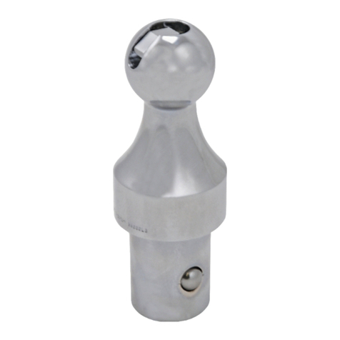
2-5/16" HITCH BALL ASSEMBLY
9 HOLE, 10" LONG, 2" SQ. SHANK
SHIM KIT
HEAD KIT
400-600 LBS. SPRING BAR
600-800 LBS. SPRING BAR
800-1200 LBS. SPRING BAR
LIFT TOOL KIT
LANYARD ASSEMBLY KIT
1/2" SERRATED HEX FLANGE HEAD KIT
HARDWARE KIT
L-BRACKET
FRAME MOUNTING BRACKET KIT
1/4" RETAINING PIN KIT
33310
33311
33312
30255
30860
32338
33314
33315
33316
33317
33318
33319
33320
33321
33322
33323
33324
ITEM DESCRIPTION
QTY
QTY
QTY
QTY
QTY
QTY
QTY
QTY
QTY
QTY
QTY
QTY
QTY
QTY
QTY
QTY
QTY
NO.
1 HEAD WELDMENT 111---1----------
2 9 HOLE, 10" LONG, 2" SQ. SHANK 111-1------------
3 5/8" HITCH PIN 111----------1---
4 5/8" HAIR PIN 111----------1---
5400-600 LBS. CENTER LINE FS
SPRING BAR 1------1---------
5600-800 LBS. CENTER LINE FS
SPRING BAR -1------1--------
5800-1200 LBS. CENTER LINE FS
SPRING BAR --1------1-------
6 HOOK SHIM 666--6-------6---
7 3/4" HARDEND FLAT WASHER 444----------4---
8 3/4"-10 X 4.5" GR. 5 HEX HEAD BOLT 222----------2---
9 1/4" “D”-PIN 222-------------2
10 3/4"-11 NYLOCK NUT 222----------2---
11 5/8" FLAT WASHER 111--------------
12 5/8" -11 HEX HEAD NUT 111--------------
13 5/8"-11 X 2.5" HEX HEAD BOLT 111--------------
14 M6-1 HEX HEAD NUT 222-------2------
15 M6 LOCK WASHER 222-------2------
16 M6 FLAT WASHER 222-------2------
17 LIFT TOOL 111-------1------
18 M6-1 X 30 HEX HEAD BOLT 222-------2------
19 LIFT BAR 111-------1------
20 1/2"-13 X 1.25" SERRATED
HEX HEAD FLANGE BOLT 444---------4--2-
21 LIFT BRACKET 222-----------11-
22 FRAME MOUNTING BRACKET 222----------- 1-
23 FRAME MOUNTING PLATE 222------------1-
24 1/2-13 X 4" CARRIAGE HEAD BOLT 444----------4-4-
25 1/2" ID HARDENED FLAT WASHER 444----------4-4-
26 1/2" LOCK WASHER 444----------4-4-
27 1/2"-13 HEX NUT 444----------4-4-
28 "L" PIN & WASHER LANYARD ASSY 2 2 2 - - - -----2---1-
29 2-5/16" 12,000 LBS. HITH BALL 1 1 1 1 - - -----------
30 1-1/4" LOCK WASHER 1111-------------
31 1-1/4" -12 HEX NUT 1111-------------

All Products limited to Vehicle Tow Rating, see Vehicle Owners Manual. Visit www.huskytow.com for Warranty Information / Tech Support /
Product Updates. 2023 Keystone Automotive Operations Inc. All Rights Reserved. 2023-Rev4 Page-20
TOWING TIPS
Driving Tow Vehicle
Good habits for normal driving need extra emphasis when towing a trailer. The additional weight of the
trailer affects acceleration and braking. Extra time should be allowed for passing, stopping and changing
lanes. Signal well in advance of a maneuver to let other drivers know your intentions. Severe bumps and
badly undulating roads can damage your towing vehicle, hitch and trailer, and should be negotiated at a
slow, steady speed. If any part of your towing system “bottoms out” or if you suspect damage may have
occurred in any other way, pull over and make a thorough inspection. Correct any problems before
resuming travel.
Turning and backing up present new problems-plan ahead. It is highly recommended that a spotter be
used when backing up to alert the driver of possible obstacles and prevent jackknifing the trailer.
Towing a trailer will change your turning radius, the longer the trailer the larger radius turn.
Driving Conditions
When driving in conditions where the pavement is wet, icy, snowy, loose gravel, grass and dirt, reduce
speed and do not make any sudden maneuvers. Allow ample distance/time for stopping and changing
lanes. If possible, wait for road conditions to improve before driving.
Follow all state, local and provincial driving and towing laws in the location you are driving in.
Not following your tow vehicle, trailer, and Husky instructions/manuals can result in a fatal accident.
Check Your Equipment
Please refer to the MAINTENANCE section. Periodically check the condition of all your towing equipment
and keep it in top condition.
Tire Inflation
Unless specified otherwise by the towing vehicle or trailer manufacturer, tires should be inflated to their
manufacturer’s towing recommendations.
Towing Vehicle and Trailer Manufacturers Recommendations
Review the owner’s manual for your towing vehicle and trailer for specific recommendations, capacities
and requirements.
Passengers in Trailers
Trailers should not be occupied while being towed. Most states enforce this regulation.
Trailer Lights, Turn Signals, Electric Brakes
Always hook up all of the trailer lights, electric brakes and break-away switch connection whenever trailer
is being towed. Also periodically check functionality of all lights before towing and repair any problems as
needed.
Trailer Loading
Proper trailer loading is very important. Heavy items should be placed close to the floor near the trailer
axle center line. The load should be balanced side to side and firmly secured in the trailer to prevent
shifting.
Remove Hitch When Not Towing
Remove hitch from receiver on towing vehicle when not towing a trailer to reduce chances of striking hitch
on driveway or other objects and reduce the chance of parts being stolen.
This manual suits for next models
2
Table of contents
Languages:
Other Husky Automobile Accessories manuals

Husky
Husky 69666C User manual

Husky
Husky 33001 User manual

Husky
Husky 33222 User manual

Husky
Husky 33100 User manual

Husky
Husky ESCORT DIGITAL User manual

Husky
Husky 31853 User manual

Husky
Husky GM UPRIGHTS Assembly instructions

Husky
Husky 30508 User manual

Husky
Husky 32220 User manual

Husky
Husky RH 34715 User manual
Popular Automobile Accessories manuals by other brands

ULTIMATE SPEED
ULTIMATE SPEED 279746 Assembly and Safety Advice

SSV Works
SSV Works DF-F65 manual

ULTIMATE SPEED
ULTIMATE SPEED CARBON Assembly and Safety Advice

Witter
Witter F174 Fitting instructions

WeatherTech
WeatherTech No-Drill installation instructions

TAUBENREUTHER
TAUBENREUTHER 1-336050 Installation instruction