Husky 31313 Assembly instructions

Page-1
All Products limited to Vehicle Tow Rating, see Vehicle Owners Manual. Visit www.huskytow.com for Warranty Information / Tech Support / Product Updates.
2021 Keystone Automotive Operations Inc. All Rights Reserved. 08/05/2021-Rev8
NOTICE
Always drive the king pin into the hitch throat and do not drop the king pin from above into the
hitch head to avoid incorrect hook-ups. Please read Operating Instruction to understand how this
important Safety Feature operates.
Failure to follow all of these instructions may result in death or serious injury
Base Rails Not
Included.
The Husky 16K S 5th Wheel is NOT to be used with rotating pin boxes or pin boxes that require a
“wedge”; such as the REESE Sidewinder, REESE Revolution, 5th Airborne Sidewinder. Use of
these products may damage this product and will void the warranty.
Assembly, Installation, Operation and
Maintenance Instructions
16K S 5th Wheel Hitch
31313 (Hitch Head & Cross Member)
31314 (2 Uprights)
P/N:
31313/31314
90-120 minutes
Dealer / Installer: Provide a copy of these instructions to the end user of this product. These
instructions provide important operating and safety information for proper usage of
this product. Demonstrate the proper use of the product with the end user. Have the
end user demonstrate that they understand the proper use of the product.
End User: Read and follow all instructions included in this manual. Ask your Dealer / Installer for
assistance if you do not understand the proper use of the product. Never remove any
decals from the product. Failure to follow these instructions can result in injury or
death.
WARNING
DO NOT EXCEED Recommended towing limits. SEE VEHICLE’S OWNER’S
MANUAL.
WARNING
WARNING
WARNING

Page-2
All Products limited to Vehicle Tow Rating, see Vehicle Owners Manual. Visit www.huskytow.com for Warranty Information / Tech Support / Product Updates.
2021 Keystone Automotive Operations Inc. All Rights Reserved. 08/05/2021-Rev8
Tools Required
The following tools will be required for installation:
(2) 7/16” wrenches/sockets
(2) ¾” wrenches/sockets
Eye protection
Gloves
Torque wrench capable of 100 ft-lbs. of torque
Package Contents
Box 31313 Contents:
Hitch head (Qty 1)
Hitch Handle w\Grip (Qty 1)
Cross Member (Qty 1)
Hardware kit
Box 31314 Contents:
Uprights (Qty 2)
Introduction
•Safety is of paramount importance in both installation and use of the Husky 16K S
Hitch System. Observe all "Cautions" and "Notes" found in this manual, as well as
common sense precautions to ensure the safety of yourself and others.
•Caution: The Husky 16K S is recommended for use only in truck beds 6 feet or
longer. A Husky EZ Roller combined with a 16K S Hitch is recommended for short
bed truck of less than 8 ft but longer than 6 ft.
•For best results, it is recommended you have your Husky 16K S system (31313
and 31314) professionally installed by a qualified technician.
•The Husky 16K S 5th Wheel Hitch System is designed to tow 5th Wheel Trailers
with a total Gross Vehicle Weight Rating up to 16,000 lbs. do not exceed the rated
capacity.
•King pin weight should never exceed 4,000 lbs.

Page-3
All Products limited to Vehicle Tow Rating, see Vehicle Owners Manual. Visit www.huskytow.com for Warranty Information / Tech Support / Product Updates.
2021 Keystone Automotive Operations Inc. All Rights Reserved. 08/05/2021-Rev8
Prior To Installation
*Check the Truck Payload and Trailer Weight as defined in Appendix A
(Checking Truck & 5th Wheel Trailer Weight Rating). Never Overload
Truck, Trailer or Hitch.
*This Hitch requires Pre-Installed Base Rails which are bolted through the
Bed of the Truck into brackets which in turn are fastened to the Truck
Chassis. DO NOT INSTALL HITCH BY FASTENING TO THE FLOOR OF THE
PICKUP BOX. The Pickup Box Floor is not strong enough to carry the
loads imposed by the trailer
*This 5th Wheel Hitch is rated for a MAXIMUM Pin Weight of 4,000 lbs and a
MAXIMUM Trailer GVW of 16,000 lbs. Exceeding Maximum ratings may
result in death, serious injury or property damage.
The distance from the back of the truck cab to the center of the King Pin (Dim
X) should be 4” greater than one-half the trailer width (Dim Y)
If towing with a short bed truck (less than 8ft but longer than 6ft.) Husky
Towing recommend the use of a Husky EZ Roller for increased turning
clearance at slow maneuvering speeds.
Do not install this 5th Wheel Hitch in a Pickup truck that has a bed shorter
than 6 ft. Towing with this combination of a short bed and 5th Wheel Hitch
could damage the truck and/or trailer. Serious injury or death could occur.
WARNING
WARNING

Page-4
All Products limited to Vehicle Tow Rating, see Vehicle Owners Manual. Visit www.huskytow.com for Warranty Information / Tech Support / Product Updates.
2021 Keystone Automotive Operations Inc. All Rights Reserved. 08/05/2021-Rev8
Assembly & Installation Procedures
1. Hitch Assembly
a) If using pre-existing base rails, ensure that the center to center (fore and aft) distance
is 22” and that there are two pairs of slots in the base rails that are 20 5/8” apart (side
to side). Otherwise contact your local dealer for proper base rail selection and
installation.
b) Place the uprights into the base rails with the decals facing the rear of the truck.
Secure the uprights to the base rails using the ½ inch diameter rail pins and secure
using the large hairclips included in the hardware bag.
c) With the Warning Label of the cross member facing to the driver side of the truck, slide
the cross-member assembly downward over the uprights. Determine the mounting
holes needed to obtain the proper height of the hitch head, and from the inside insert
the four 1/2" diameter bolts into the appropriate cross member mounting holes and
thru each body side. Note: inserting the bolts from the inside will put the lock
nuts on the outside of the cross member, this will ensure that the proper torque
will be applied to the lock nuts.

Page-5
All Products limited to Vehicle Tow Rating, see Vehicle Owners Manual. Visit www.huskytow.com for Warranty Information / Tech Support / Product Updates.
2021 Keystone Automotive Operations Inc. All Rights Reserved. 08/05/2021-Rev8
d) Shims 32043 are provided to adjust crossmember and uprights. Use only if needed
for proper alignment.
e) NOTE: See page 10 for complete height adjusting instructions.
IMPORTANT: The ideal centerline location of the 5thWheel Hitch should be positioned
between 1” and 3” forward of the Center of the Rear Axle once installed in the base rails.
This position may be limited by your specific base rail installation. Always verify this
information before towing down the road and also confirm that you will have adequate
turning clearance between the back of the truck cab and the nose of the 5
th
wheel trailer.
Place shim on either side
as needed
Shim 32043

Page-6
All Products limited to Vehicle Tow Rating, see Vehicle Owners Manual. Visit www.huskytow.com for Warranty Information / Tech Support / Product Updates.
2021 Keystone Automotive Operations Inc. All Rights Reserved. 08/05/2021-Rev8
Hitch Handle Assembly
a. Place the hitch head onto the adjustable cross member and secure with the
supplied 3/8" clevis pins and hair pins. Check for freedom of movement.
b. Rotate the handle shaft while pulling it straight out, once the shaft starts sliding
out of the guide tube pull it all the way out to lock the hitch head in the open
position.
c) Hold the handle with the grip pointed upward and slide the handle onto the
handle shaft.
d) Fasten the hitch handle using the supplied ¼-20 HEX HEAD BOLT and ¼-20
NYLON LOCK NUT. Tighten lock nut until it comes in contact with the tube.
e) Use a wrench to trip the lock mechanism to close the hitch head. Be careful to keep
your body away from any moving parts. The handle should rotate and point down
towards the bed of the pickup truck.
Trip lock mechanism

Page-7
All Products limited to Vehicle Tow Rating, see Vehicle Owners Manual. Visit www.huskytow.com for Warranty Information / Tech Support / Product Updates.
2021 Keystone Automotive Operations Inc. All Rights Reserved. 08/05/2021-Rev8
f) View of final assembly of 16K S 5th Wheel System.
g) Rotate the handle straight up and pull out until it is in the locked open position.
Understanding The Safety Features Of your New HUSKY 5th
Wheel.
The HUSKY 16K S 5th wheel hitch comes standard with a visual aid to indicate what the
current status is of the king pin locking mechanism. Note that the view shown directly
below has a red indicator sleeve on the handle shaft. This is intended to give a quick visual
aid as to whether the hitch head is closed or open. In the two pictures below it is open. The
cross member, uprights and base rails removed for clarity.
RED INDICATOR
SLEEVE
RED INDICATOR
SLEEVE

Page-8
All Products limited to Vehicle Tow Rating, see Vehicle Owners Manual. Visit www.huskytow.com for Warranty Information / Tech Support / Product Updates.
2021 Keystone Automotive Operations Inc. All Rights Reserved. 08/05/2021-Rev8
There is another visual aid that indicates if the hitch head is closed and locked. This is
shown in the picture below with a green shaft that protrudes from the side of the hitch
head. If the king pin has been correctly installed into the mouth of the hitch head the slide
bar will close, the red indicating sleeve will disappear and the green indicator pin will
protrude out as shown below. Cross member, uprights and base rails removed for clarity.
At no time should both the green and red indicator be showing, if this is the case there is
damage to the hitch head and it should not be used. Carefully inspect the hitch for any
damage, also confirm that the handle is installed correctly according to the assembly
instructions in this manual.

Page-9
All Products limited to Vehicle Tow Rating, see Vehicle Owners Manual. Visit www.huskytow.com for Warranty Information / Tech Support / Product Updates.
2021 Keystone Automotive Operations Inc. All Rights Reserved. 08/05/2021-Rev8
Operating Instructions
About Your Husky 16K S
The Husky 16K S 5th Wheel Hitch System is designed to tow 5th Wheel Trailers with a
Gross Vehicle Weight Rating up to 16,000 lbs. Do not exceed the rated capacity as it will
create an unsafe towing condition. It has a 4-way swivel head, its height is adjustable from
14 to 17 inches in one-inch increments and is removed from the bed of the truck by pulling
4 rail pins.
Preparing For First Use
Your Husky 16K S 5th wheel system is now installed and you're anxious to be on your way
down the road. You're almost there but take a few minutes to ensure your hitch is set up
properly for your truck/coach combination by following the steps below.
1. Verify that the cross member is set at the proper height to provide a minimum of 6"
clearance between the bottom of the trailer nose and the top of the truck bedsides and
allows for a level-towing attitude of the 5th Wheel Trailer (See Figure 1 below).
Figure 1
With top face of head level measure up to top of pickup box (dimension Y in Figure 1). On
the trailer measure up from the face of the pin box to the underneath of the trailer
(dimension X in Figure 1). Measurement X less measurement Y gives the amount of
clearance between the top of the pickup box and the underneath of the trailer.
At a minimum this should be 6”, if the trailer and tow vehicle are going off-road then this
needs to be 8” to 10”.
If this dimension is less than 6” DO NOT USE THIS TRAILER WITH THIS TOW VEHICLE.
Severe damage may occur to both the pickup box and the trailer.
WARNING

Page-10
All Products limited to Vehicle Tow Rating, see Vehicle Owners Manual. Visit www.huskytow.com for Warranty Information / Tech Support / Product Updates.
2021 Keystone Automotive Operations Inc. All Rights Reserved. 08/05/2021-Rev8
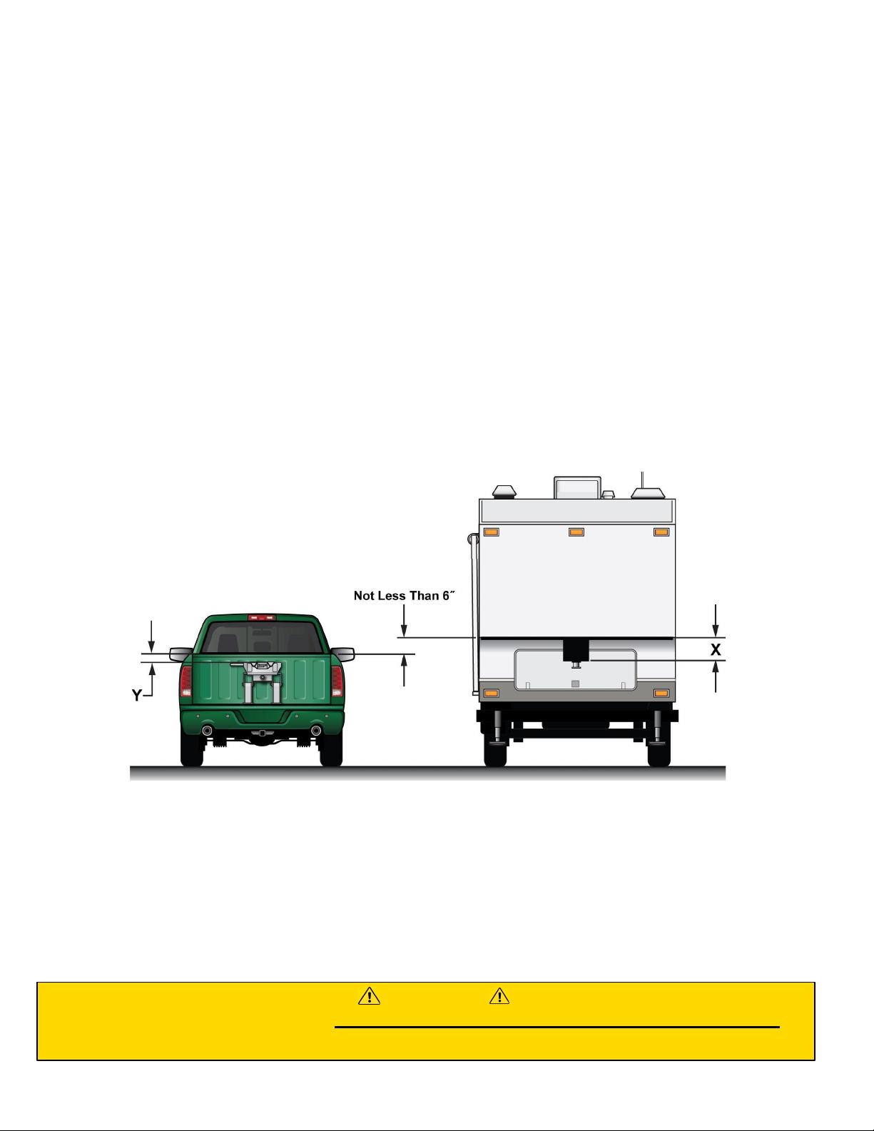
2. If necessary, adjust the cross member to the proper height, ensuring the fasteners are
re-torqued to 75 ft. lbs.
3. Ensure the 5th Wheel Trailer wheels are blocked front & rear & that the rear stabilizer
jacks are fully retracted.
4. Also make sure the 5th Wheel Trailer landing leg feet are on a stable surface.
5. With hitch head level, set trailer king pin box ½” to 1” below hitch so trailer will ride up
and onto hitch. Back Up the truck under the trailer so the king pin enters the hitch.
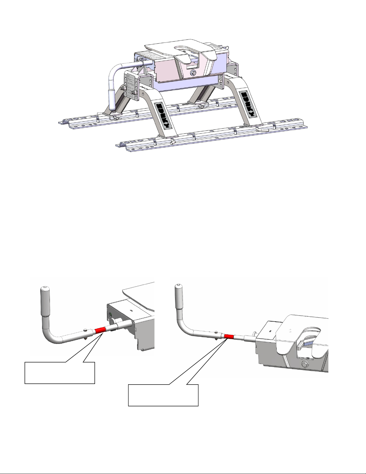
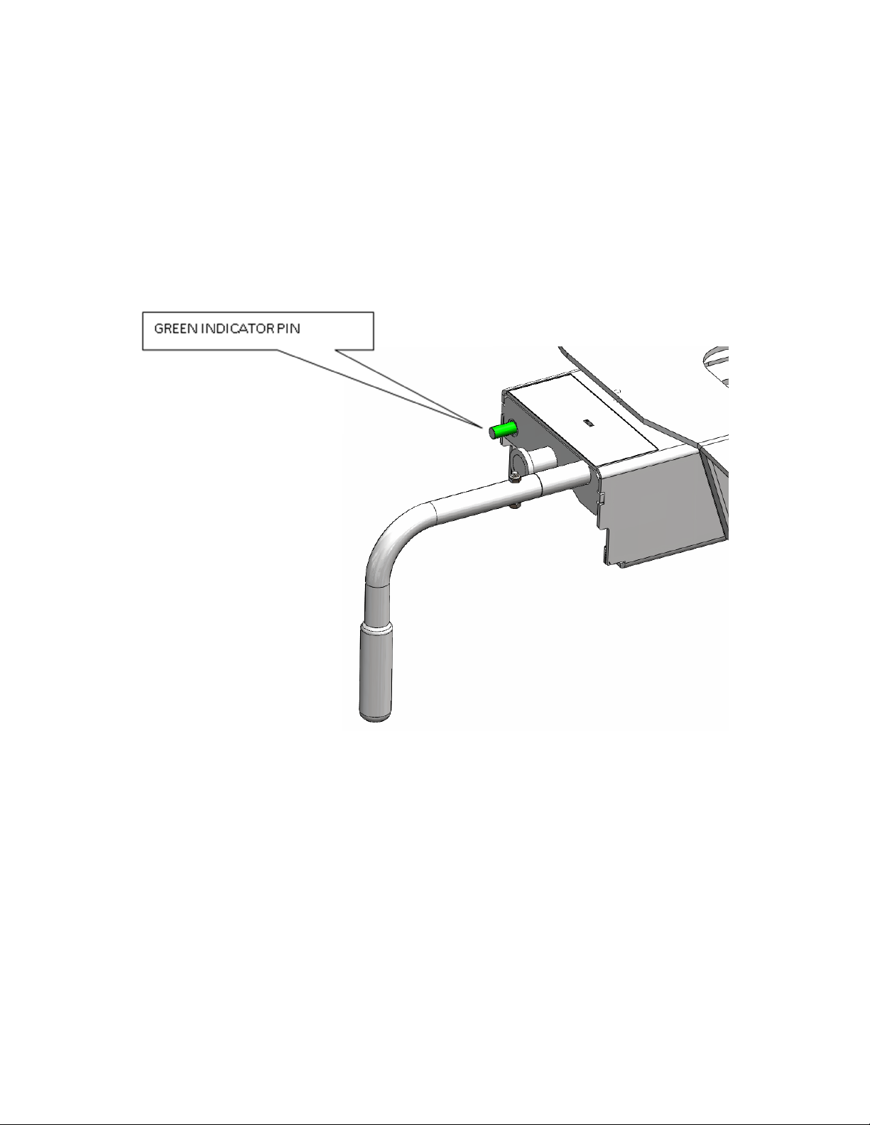
6. Rotate the handle of the hitch 180 degrees so that the handgrip is pointing straight up
& pull the handle out until the slide bar is held open by the king pin trip mechanism.
The handle shaft has a red indicating sleeve to provide a quick visual reference that
the handle is not closed. You should also note that the green indicator pin is not
protruding from the side of the hitch head.
7. Slowly back the truck so that the bottom plate of the king pin box slides onto the 5th
wheel plate & the king pin slides fully into the throat of the hitch head. Set the parking
brake of the truck & place the transmission into park.
8. Visually verify the slide bar has closed behind the king pin and the king pin box is
resting on the 5th wheel plate. Positively lock the slide bar by rotating the handle
clockwise so the handgrip is pointing straight down at the bed of the truck. The red
indicator sleeve on the handle shaft should not be visible when correctly hitched up
and the green indicator shaft should be protruding from the side of the hitch head.
9. Never back the tow vehicle under the trailer king pin and then lower the king pin into
the hitch. This will result in high pinning and will result in hitch damage and possible
vehicle damage, injury or death!
WARNING

Page-11
All Products limited to Vehicle Tow Rating, see Vehicle Owners Manual. Visit www.huskytow.com for Warranty Information / Tech Support / Product Updates.
2021 Keystone Automotive Operations Inc. All Rights Reserved. 08/05/2021-Rev8
NEVER LOWER THE KING PIN INTO THE HITCH
USING THE TRAILER JACKS. THIS IS A VERY
DANGEROUS PRACTICE AND WILL RESULT IN THE
KING PIN SITTING ON TOP OF HITCH INSTEAD OF
INSIDE. THE TRAILER COULD THEN BECOME
DETACHED FROM THE TRUCK DURING TOWING
CAUSING SERIOUS DAMAGE AND POSSIBLY INJURY
OR DEATH.
10. Before towing perform a tug test as follows: Ensure the landing gear of the 5th
Wheel Trailer are extended to the ground, chock the tires, and attach the electrical &
breakaway connectors to the proper receptacles in accordance with your 5th Wheel
Trailer owner's manual. Then apply the trailer brakes, and slowly try to pull the trailer
forward. The trailer should prevent the truck from moving.
11. Remove the blocks from the wheels of the 5th Wheel Trailer; fully retract the trailer
jacks and double check that the hitch is properly attached to your tow vehicle.
Uncoupling Your Trailer
1. Block your 5th Wheel Trailer wheels front & rear.
2. If necessary, start your truck & back up against the king pin to relieve pressure on the
slide bar. Set the parking brake, put the transmission into park and then turn off your
vehicle.
3. Extend the landing gear of the 5th Wheel Trailer until the weight of the 5th Wheel
Trailer is just off of the 5th wheel plate of the hitch. Do not exceed 1/16" gap between
the bottom plate of the king pin box and the tabletop of the hitch. Caution: Raising
the 5th Wheel Trailer too high while still connected can damage the hitch head
as well as components of your 5th Wheel Trailer. Do not extend the rear
stabilizers of the 5th Wheel Trailer prior to or during uncoupling.
4. Disconnect the electrical and breakaway connectors in accordance with your 5th
Wheel Trailer owner's manual. With the rubber grip of the handle pointing straight
down towards the bed of the truck, pull it straight out and then rotate it straight up to
lock the handle in the out position.
5. You are now ready to pull your truck slowly away from the 5th Wheel Trailer.
WARNING

Page-12
All Products limited to Vehicle Tow Rating, see Vehicle Owners Manual. Visit www.huskytow.com for Warranty Information / Tech Support / Product Updates.
2021 Keystone Automotive Operations Inc. All Rights Reserved. 08/05/2021-Rev8
DO NOT TRIP THE HITCH MECHANISM BY HAND AS THIS CAN RESULT
IN INJURY . IN NORMAL OPERATION LEAVE THE HITCH OPEN UNLESS
IT IS COUPLED TO A TRAILER.
ALWAYS PULL ON THE HANDLE TO OPEN THE HITCH BEFORE
COUPLING THE TRAILER.
Maintenance
1. After coupling, always visually check that the slide bar has closed completely across
the rear of the king pin and that the red indicator sleeve on the handle shaft is not
showing. Also confirm that the green indicating pin is “popped out” from the side of the
hitch head. IMPORTANT! Both indicating features should never both be
showing when you are done hitching up for travel.
2. After the first 100 miles, and at least once a year thereafter, inspect all bolts for proper
tightness. Retighten nuts if needed. All fasteners ½” diameter, torque to 75 ft-lbs.
3. Once or twice a week when traveling, apply a few drops of lubricant to the top of the
pivot pin collar. The pivot pins hold the tabletop or "horseshoe" in place on the hitch
head and can be found by locating the hex head bolts on the front and rear of the hitch
head.
4. Once or twice a year, apply a light coating of wheel bearing grease to the surfaces of
the slide bar that holds the king pin in place. For best results, apply the grease with the
slide bar in the closed position. Caution: The slide bar can close with heavy force.
Use extreme care to keep fingers, hands, extremities & clothing out of the path
of the slide bar. Failure to do so could result in severe injury.
5. Periodically inspect your Husky 16K S for wear or damage. If excessive wear or
damage is found, contact your installing dealer or HUSKY technical support staff at
www.huskytow.com or 1-877-544-4449.
6. Husky Towing Products recommends the use of a lube disc, contact your local Husky
dealer to purchase one
WARNING

Page-13
All Products limited to Vehicle Tow Rating, see Vehicle Owners Manual. Visit www.huskytow.com for Warranty Information / Tech Support / Product Updates.
2021 Keystone Automotive Operations Inc. All Rights Reserved. 08/05/2021-Rev8
TOWING TIPS
Driving Tow Vehicle
Good habits for normal driving need extra emphasis when towing a trailer. The additional weight of the trailer affects
acceleration and braking. Extra time should be allowed for passing, stopping and changing lanes. Signal well in advance of a
maneuver to let other drivers know your intentions. Severe bumps and badly undulating roads can damage your towing vehicle,
hitch and trailer, and should be negotiated at a slow, steady speed. If any part of your towing system “bottoms out” or if you
suspect damage may have occurred in any other way, pull over and make a thorough inspection. Correct any problems before
resuming travel.
Turning and backing up present new problems-plan ahead. It is highly recommended that a spotter be used when backing up
to alert the driver of possible obstacles and prevent jack knifing the trailer.
Towing a trailer will change your turning radius, the longer the trailer the larger radius turn.
Driving Conditions
When driving in conditions where the pavement is wet, icy, snowy, loose gravel, grass and dirt, reduce speed and do not make
any sudden maneuvers. Allow ample distance/time for stopping and changing lanes. If possible, wait for road conditions to
improve before driving.
Follow all state, local and provincial driving and towing laws in the location you are driving in.
Not following your tow vehicle, trailer, and Husky instructions/manuals can result in a fatal accident.
Check Your Equipment
Please refer to the MAINTENANCE section. Periodically check the condition of all your towing equipment and keep it in top
condition.
Tire Inflation
Unless specified otherwise by the towing vehicle or trailer manufacturer, tires should be inflated to their manufacturer’s towing
recommendations.
Towing Vehicle and Trailer Manufacturers Recommendations
Review the owner’s manual for your towing vehicle and trailer for specific recommendations, capacities and requirements.
Passengers in Trailers
Trailers should not be occupied while being towed. Most states enforce this regulation.
Trailer Lights, Turn Signals, Electric Brakes
Always hook up all of the trailer lights, electric brakes and break-away switch connection whenever trailer is being towed. Also
periodically check functionality of all lights before towing and repair any problems as needed.
Trailer Loading
Proper trailer loading is very important. Heavy items should be placed close to the floor near the trailer axle centerline. The
load should be balanced side to side and firmly secured in the trailer to prevent shifting.
Remove Hitch When Not Towing
Remove hitch from receiver on towing vehicle when not towing a trailer to reduce chances of striking hitch on driveway or other
objects and reduce the chance of parts being stolen.
Maintenance (All products)
Keep hitch ball or gooseneck lubricated when used.
When not in use, remove ball mount, shank or gooseneck ball and store in clean, dry place.
Keep hitch ball, gooseneck, receiver and 5th wheel clean and lubricated.
Lubricate the bars and trunnion bar holes on a weight distribution hitch.
At The Beginning of Every Towing Day (All Products)
Clean hitch ball or gooseneck ball and coat lightly with grease.
Lubricate the top plate and moving parts of your 5th wheel hitch before coupling.
Check for worn or damaged parts. Check the torque of all hardware.
Check to see that all electrical hook-ups are in working order and that the safety chains are securely connected.
If electric brakes are used ensure the emergency break away cable is attached to the tow vehicle.
Towing safely is the responsibility of the driver of the vehicle. Failure to tow safely can result in vehicle damage, bodily injury or
death.

Page-14
All Products limited to Vehicle Tow Rating, see Vehicle Owners Manual. Visit www.huskytow.com for Warranty Information / Tech Support / Product Updates.
2021 Keystone Automotive Operations Inc. All Rights Reserved. 08/05/2021-Rev8
Trouble Shooting
Problem What To Look For Solution
Hitch is difficult to install and
remove from the base rails. Hitch is not assembled correctly. Refer to Hitch Assembly section for
proper assembly instructions.
Base Rails are not parallel with each
other.
Use spacer to hold both base rails
parallel while loosening and
retightening the carriage bolts.
Truck bed collapsing around carriage
bolts in base rails.
Install proper spacers between the
base rail and corrugations. Refer to
installation instructions for specific
directions.
Hitch will not hook up to the trailer
king pin.
Incorrect king pin height The king pin plate should be ½” to
1” below the 5th wheel skid plate.
Excessive angle between hitch head
and king pin.
Level trailer or tow vehicle with
blocks under the wheels.
Lube disc is too thick. Check thickness of lube disc. It
should not exceed 3/16”.
Bent king pin. Contact your local dealer for
replacement.
Hitch is difficult to unhook from
trailer.
King pin is resting on the locking
bar, preventing it from sliding open.
Remove pressure on the locking bar
by blocking the trailer wheels in
front and behind.
With trailer wheels blocked and
truck running, place truck in reverse,
set the parking brake and then put
truck in park and turn off the engine.
This should relieve the pressure on
the locking bar.
Incorrect king pin height. Trailer is up to high; retract the
trailer landing legs to remove tension
from slide bar.
Excessive angle between hitch head
and king pin.
Level trailer or tow vehicle with
blocks under the wheels.
Lube disc is too thick. Check thickness of lube disc. It
should not exceed 3/16”.
Bent king pin. Contact your local dealer for
replacement.
Locking bar is difficult to close or
open.
New hitch head. Contact your local dealer for
replacement.
Locking bar is worn. Inspect locking bar for wear or
damage. Look for a ridge at the front
edge of the locking bar.
If found, file away the ridge and
lubricate locking bar. Contact the
Husky warranty dept. at 1-877-544-
4449, or contact your dealer/installer
if locking bar is damaged rather than
worn.

Page-15
All Products limited to Vehicle Tow Rating, see Vehicle Owners Manual. Visit www.huskytow.com for Warranty Information / Tech Support / Product Updates.
2021 Keystone Automotive Operations Inc. All Rights Reserved. 08/05/2021-Rev8
Problem What To Look For What To Look For
Locking bar does not lock into the
open position.
Missing spring on trip mechanism. Contact technical support for
replacement spring.
Missing or damaged trip mechanism. Inspect trip mechanism. The trip
mechanism should not be bent, and
the spring should be attached and
have good tension.
Table top distorted/cracking at the
pivot point.
Wear and tear. Replace hitch head, contact technical
support.
Green and Red indicator are showing
at the same time.
Broken return spring on king pin bar
clamp.
Contact technical support for
replacement spring.
Handle installed incorrectly. Review assembly instructions to
ensure correct installation.
Linkage mechanism is damaged. Turn head upside down and inspect
pivot linkage for green indicator pin.

Page-16
All Products limited to Vehicle Tow Rating, see Vehicle Owners Manual. Visit www.huskytow.com for Warranty Information / Tech Support / Product Updates.
2021 Keystone Automotive Operations Inc. All Rights Reserved. 08/05/2021-Rev8
Parts Listing
16K S HEAD AND CROSS MEMBER PACKAGE
31313
2 UPRIGHTS PACKAGE
31314
CROSS MEMBER PACKAGE
31452
16K S HEAD AND HANDLE PACKAGE
31453
16K S COMPLETE HARDWARE KIT
31455
16K S HITCH HEAD RETAINING PINS
31456
SHIM KIT
32043
ITEM NO. Description
QTY
QTY
QTY
QTY
QTY
QTY
QTY
1 PIN, 1/2" BASE RAIL 4---4--
2 PIN, 1/2" HAIR 4---4--
3 UPRIGHTS (NOT INCLUDED WITH 31313) -2-----
4 HEX HEAD BOLT, 1/4-20 UNC X 1.375 LG 1--1---
5HANDLE 1--1---
6 NUT, NYLON LOCK, 1/4-20 UNC 1--1---
7 16K S 5TH WHEEL HEAD ASSEMBLY 1--1---
8 PIN, 3/8" HAIR 2- -222-
9 PIN, 3/8" CLEVIS 2- -222-
10 CROSS MEMBER 1-1----
11 WASHER FLAT .531 ID X 1.250 OD X .10 THK, 4-4-4--
12 BOLT, HEX, 1/2-13 UNC X 5 LG 4-4-4--
13 NUT, NYLON LOCK, 1/2-13 UNC 4-4-4--
14 BASE RAIL FOR 5TH WHEEL(NOT INCLUDED) -------
15 SHIM KIT -14----14

Page-17
All Products limited to Vehicle Tow Rating, see Vehicle Owners Manual. Visit www.huskytow.com for Warranty Information / Tech Support / Product Updates.
2021 Keystone Automotive Operations Inc. All Rights Reserved. 08/05/2021-Rev8
Warranty Terms:
5 Year Limited Warranty:
This warranty applies solely to Husky 5th Wheel Hitch manufactured by Keystone Automotive Operations
Inc. for Husky Towing Products.
Husky Towing Products and Keystone Automotive Operations Inc. make no guarantees or warranties for
products not manufactured by Keystone Automotive Operations Inc. Such products are covered solely
under any applicable warranty of the manufacturer. It is always recommended that the operating
instructions and warranty instructions provided by the manufacturer are followed.
Keystone Automotive Operations Inc. warrants its products to be free from manufacturing and material
defects to the original purchaser for the length of warranty stated above from the date of retail purchase. If
any products are found to have a manufacturing or material defect, the product will be replaced or
repaired at the option of Husky Towing Products and Keystone Automotive Operations Inc. with proof of
purchase by the original purchaser. The original purchaser shall pay all transportation and shipping costs
associated with the return of the defective product and the defective product shall become the property of
Keystone Automotive Operations Inc.
The Warranty applies to Keystone Automotive Operations Inc. products used for individual and
recreational purposes. Commercial usage of the Keystone Automotive Operations Inc. products limits the
warranty to 90-days from date of purchase.
The Warranty applies only to Keystone Automotive Operations Inc. products which are found to be
defective in manufacturing or material. This warranty does not apply to normal wear and tear of the finish
placed on Keystone Automotive Operations Inc. products.
Husky Towing Products and Keystone Automotive Operations Inc. are not responsible for any labor costs
incurred for removal or replacement of the defective product.
Husky Towing Products and Keystone Automotive Operations Inc. are not responsible for repair or
replacement of any product under the limited warranty where the product was improperly installed,
misapplied, altered, abused, neglected, overloaded, misused or damaged as a result of an accident,
including any use of the product not in accordance with all product operating and safety instructions.
Without limiting the generality of the foregoing, Husky Towing Products and Keystone Automotive
Operations Inc. shall under no circumstances be liable for any incidental or consequential loss or damage
whatsoever arising out of, or in any way relating to any such breach of warranty or claimed defect in, or
non-performance of the products. Some states do not allow the exclusion or limitation of incidental or
consequential damages, so the above exclusion or limitation may not apply to you.
This limited warranty gives you specific legal rights, and you may also have other rights that vary from
state to state.

Page-18
All Products limited to Vehicle Tow Rating, see Vehicle Owners Manual. Visit www.huskytow.com for Warranty Information / Tech Support / Product Updates.
2021 Keystone Automotive Operations Inc. All Rights Reserved. 08/05/2021-Rev8
Appendix A
Weighing Truck and 5th Wheel Trailer.
Weigh the Truck and 5th Wheel on a public weigh scale. Public weigh scales can be found
at Some Truck Stops, or they can be located from Yellow pages or on the Internet.
Weigh the Truck and 5th Wheel in 3 stages as shown in the sketch.
Step 1, Weigh the both the Truck and 5th Wheel. This is weight 1; this will give the
GCW (Gross Combination Weight) of the Truck and 5th Wheel Trailer. The GCW must
not exceed the GCWR (Gross Combination Weight Rating) for the Truck. The GCWR
of a truck depends on engine size, transmission, rear axle ratio, tow package and
other factors. The manufacturer or dealer will be able to find the GCWR from the VIN
(Vehicle Identification Number) of the truck.
Step 2, Drive the front wheels of the truck off the weighing platform. Weigh the rear
wheels of the truck and the 5th Wheel Trailer wheels. This is weight 2, Subtract
weight 2 from the weight 1; the result is the GAW (Gross Axle Weight) for the front
axle of the truck. The GAWR (Gross Axle Weight Rating) for the front axle can be
found on the VIN plate on the driver’s side door pillar, the measured front GAW must
not exceed the front GAWR on the VIN plate.
Step 3, Drive the rear wheels of the truck off the weighing platform; this should leave
only 5th Wheel Axles remaining on the weighing platform. This is weight 3, Subtract
weight 3 from the weight 1 and this is the GVW (Gross Vehicle Weight) of the truck.
The measured GVW must not exceed the GVWR found on the VIN plate. Subtract
weight 3 from weight 2 and this is the measured GAW of the rear axle of the truck
and must not exceed the GAWR of the rear axle found on the VIN plate. Weight 3 is
also the GAW of the 5th Wheel; this weight should not exceed the GAWR on the plate
on the 5th Wheel.

Page-19
All Products limited to Vehicle Tow Rating, see Vehicle Owners Manual. Visit www.huskytow.com for Warranty Information / Tech Support / Product Updates.
2021 Keystone Automotive Operations Inc. All Rights Reserved. 08/05/2021-Rev8
Summarizing Weighing
GCW (Truck & 5th Wheel Trailer) = weight 1
GAW of front axle (Truck) = weight 1 – weight 2
GVW (Truck) = weight 1 – weight 3
GAW of rear axle (Truck) = weight 2 – weight 3
GAW of axles (5th Wheel Trailer) = weight 3
EXCEEDING ANY WEIGHT RATING IS HAZARDOUS. OVERLOADING OF TRUCK AND/OR 5th
WHEEL TRAILER CAN LEAD TO TIRE FAILURE, BRAKE FADE AND OVERHEATING OF THE
TRUCK ENGINE OR TRANSMISSION. OVERLOADED VEHICLES ARE MORE UNSTABLE AND
UNPREDICTABLE EVEN IN NORMAL DRIVING CONDITIONS.
WARNING

Tous les produits sont limités à l'évaluation de la capacité de remorquage du véhicule. Consultez www.huskytow.com pour les informations sur la garantie /
l'assistance technique / les mises à jour des produits. 2021 Keystone Automotive Operations Inc. Tous droits réservés. 05/08/2021-Rév8 Page - 20
REMARQUE
Enfoncez toujours le pivot d'attelage dans la gorge de l’attelage. N’essayez jamais de faire rentrer le
pivot d’attelage dans la tête par le haut afin d'éviter un mauvais attelage. Veuillez lire les instructions
d'utilisation pour comprendre le fonctionnement de cet important dispositif de sécurité.
Le non-respect de toutes ces instructions peut entraîner des blessures graves ou la
mort.
Rails de base
non fournis
La sellette Husky 16K S ne doit PAS être utilisée avec des boîtiers à broches rotatives ou des
boîtiers à broches nécessitant une “cale”, comme le REESE Sidewinder, le REESE Revolution, le
5e Airborne Sidewinder. L'utilisation de ces équipements peut endommager ce produit et annule la
garantie.
Instructions de montage, d'installation,
d'utilisation et de maintenance
Sellette d’attelage 16K S
31313 (Tête d'attelage et traverse)
31314 (2 montants)
P/N:
31313/31314
90-120 minutes
Revendeur /
Installateur :
Fournissez une copie de ces instructions à l'utilisateur final de ce produit. Ces
instructions contiennent des informations importantes sur le fonctionnement et la
sécurité pour une utilisation normale de ce produit. Présentez l'utilisation normale du
produit à l'utilisateur final. Demandez lui de confirmer qu'il a tout compris.
Utilisateur final : Lisez et suivez toutes les instructions présentes dans ce manuel. Demandez l'aide de
votre revendeur / installateur si vous ne comprenez pas comment utiliser ce produit.
Ne retirez jamais les autocollants du produit. Le non-respect de ces instructions peut
entraîner des blessures ou la mort.
AVERTISSEMENT
NE PAS DÉPASSER les limites de remorquage recommandées. CONSULTEZ LE MANUEL DU
PROPRIÉTAIRE DU VÉHICULE.
AVERTISSEMENT
AVERTISSEMENT
AVERTISSEMENT
This manual suits for next models
4
Table of contents
Languages:
Other Husky Automobile Accessories manuals