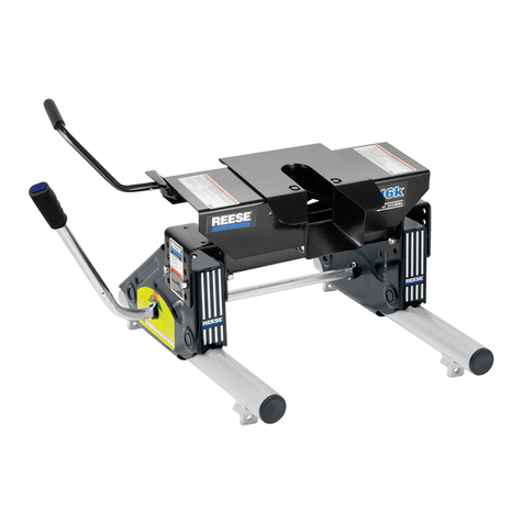
Husky 32220 User manual

Page-1
All Products limited to Vehicle Tow Rating, see VehicleOwners Manual. Visit www.huskytow.com for Warranty Information /
Tech Support / Product Updates. 2020 Keystone Automotive Operations Inc. All Rights Reserved. 08/27/2020-Rev8
Dealer / Installer:
Provide a copy of these instructions to the end user of this product. These
instructions provide important operating and safety information for proper usage of
this product. Demonstrate the proper use of the product with the end user. Have the
end user demonstrate that they understand the proper use of the product.
End User:
Read and follow all instructions included in this manual. Ask your Dealer / Installer for
assistance if you do not understand the proper use of the product. Never remove any
decals from the product.
APPLICATION: For use on short bed pickup applications no less than 6-1/2 feet long.
DO NOT EXCEED Recommended towing limits. SEE VEHICLE’S OWNER’S MANUAL.
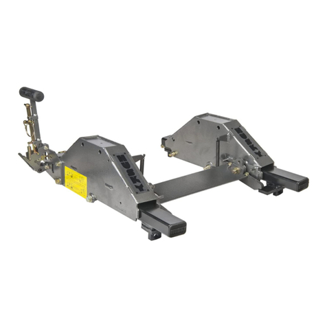
NOTE: The "HUSKY ROLLER" is to be used only with 5th wheel trailers which weigh
16,000 lbs. or less. Never use with heavier trailers. You will need to disassemble the
uprights from your current 5th wheel to install the "HUSKY ROLLER". The "HUSKY
ROLLER" takes the place of those uprights.
Caution: The "HUSKY ROLLER" will reposition your 5th wheel 9" rearward.
HOWEVER this will NOT guarantee complete truck cab/trailer clearance when
towing & making sharp turns. See page 2, "Truck Cab and 5th Wheel Trailer
Clearance".
Caution: Do not install mounting/base rails over plastic bed liners. Plastic bed liners
must be cut out of the way. Rails may be installed on spray in liners.
Note: Consult spray liner installer for recommended curing time.
IMPORTANT: The installation of the Husky Roller 32220 REQUIRES the installation of
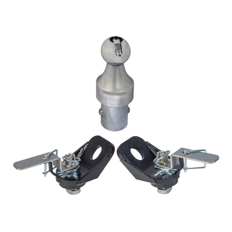
the Husky Center Bolt Kit 32059. CENTER BOLT KIT IS INCLUDED.
WARNING! Never exceed the
towing capacity of the tow vehicle.
The "Husky Roller" will only work in the base rail slots
spaced 20-5/8" apart.
Only use Husky 5th Wheel Hitches with this product.
Assembly, Installation, Operation and
Maintenance Instructions
“HUSKY ROLLER”
P/N: 32220
90-120 minutes
Page-2
All Products limited to Vehicle Tow Rating, see Vehicle Owners Manual. Visit www.huskytow.com for Warranty Information /
Tech Support / Product Updates. 2020 Keystone Automotive Operations Inc. All Rights Reserved. 08/27/2020-Rev8
Truck Cab and 5th Wheel Trailer Clearance
NOTE! Not all 5th wheel trailers are the same. It is the driver's responsibility to determine what
kind of trailer to cab clearance will result at hook-up time. This can be determined by measuring
the distance from the center of the 5th wheel hitch opening to the rear of the truck cab ("X"
DISTANCE) and adding 4 inches to it. Then measure the width of the trailer and divide this in half,
this will result in the ("Y" DISTANCE). The "X" DISTANCE must be equal to or greater than the "Y"
DISTANCE. This does not mean that your 5th wheel trailer cannot still come in contact with the
truck cab. Always have a spotter to help be your eyes to warn you when to stop turning
TOOLS REQUIRED:
DRILL*
5/8" DRILL BIT*
3/16" ALLEN WRENCH
7/16" WRENCH & SOCKET
9/16 WRENCH & SOCKET
3/4" WRENCH & SOCKET
TORQUE WRENCH (150 LBS.-FT. MIN.)
*These tools only required if you do not have
a center bolt kit installed in your base rails.
All "Husky Roller" fasteners are grade 5

Page-3
All Products limited to Vehicle Tow Rating, see Vehicle Owners Manual. Visit www.huskytow.com for Warranty Information /
Tech Support / Product Updates. 2020 Keystone Automotive Operations Inc. All Rights Reserved. 08/27/2020-Rev8
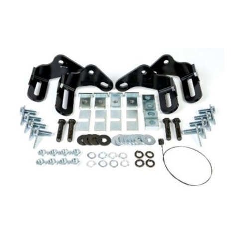
Roller Parts Listing
Use only the supplied bolts, nuts, and washers
to install this kit. All nuts and bolts are Grade 5
unless specified otherwise.

Page-4
All Products limited to Vehicle Tow Rating, see Vehicle Owners Manual. Visit www.huskytow.com for Warranty Information /
Tech Support / Product Updates. 2020 Keystone Automotive Operations Inc. All Rights Reserved. 08/27/2020-Rev8
CENTER BOLT INSTALLATION
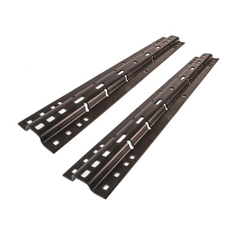
1. Prior to assembly of "HUSKY ROLLER", be sure that your base rails are properly installed and
square with each other. Measure diagonally across the rails. See Figure 1. Measurements "X" &
"Y" should be within 3/16" of each other. These measurements are required for proper fit and
function of the "HUSKY ROLLER". If using pre-existing base rails, ensure that the center to center
(fore and aft) distance is 22” and that there are two pairs of slots in the base rails that are 20-5/8"”
apart (side to side) Otherwise contact your local dealer for proper base rail selection and installation.
2. Install the included Husky Center Bolt kit, which is REQUIRED.
3. Locate the center hole in each base rail. See Figure 1. Using these holes as a guide, drill a 5/8”
hole through the truck bed. Confirm that the fuel tank, brake/fuel lines, electrical wires
located under the bed are not in the path of drilling the holes in this step.
4. Drop the 5/8 carriage bolts supplied through the center bolt locations, through the truck bed.
5. Check the corrugations in the truck bed floor and place the spacer plate in the correct position
as shown. See Figure 2.
Base Rails Not Included

Page-5
All Products limited to Vehicle Tow Rating, see Vehicle Owners Manual. Visit www.huskytow.com for Warranty Information /
Tech Support / Product Updates. 2020 Keystone Automotive Operations Inc. All Rights Reserved. 08/27/2020-Rev8
BASE RAIL
BED
CORRUGATION
BASE RAIL
BED
CORRUGATION
2 spacer plates must
be installed on each
carriage head bolt
and oriented in an
"X" shape.
2 spacer plates must
be installed on each
carriage head bolt
and oriented in an
"X" shape.
Spacer plates below
bed corrugation. 1 Spacer plate above bed corrugation &
1 spacer plate below bed corrugation.
Figure 2
6. Tighten the 5/8” hex nuts to 150 lbs.-ft.
7. Once the bed rails are square and the center bolt kit is properly installed you can start the
installation of the "HUSKY ROLLER".

Page-6
All Products limited to Vehicle Tow Rating, see Vehicle Owners Manual. Visit www.huskytow.com for Warranty Information /
Tech Support / Product Updates. 2020 Keystone Automotive Operations Inc. All Rights Reserved. 08/27/2020-Rev8
"HUSKY ROLLER" ASSEMBLY
GREASE GREASE
GREASE LATCH PIN #2
LATCH
PIN #1
Figure 3
Figure 4
Hole #1
Hole #2
Hole #3
Hole #4
REAR OF
TRUCK
1. Apply grease toALL areas indicated by arrows. See Figure #3 for all areas requiring grease.
2. Install the EZ Roller Housings into the base rails at the 20-5/8” slot locations. Be sure they are
oriented as shown in Figure 4 above.
3. Slide long tube assembly into Hole #1 of the passenger side roller assembly so that the latch
pin #2 inserts into hole #2. See Figure #4.

Page-7
All Products limited to Vehicle Tow Rating, see Vehicle Owners Manual. Visit www.huskytow.com for Warranty Information /
Tech Support / Product Updates. 2020 Keystone Automotive Operations Inc. All Rights Reserved. 08/27/2020-Rev8
4. Place the large flat washer and the compression spring over the hole on the driver’s side roller
assembly. Make sure the spring is aligned with the end of Long Tube. Insert the Flat Handle
Weldment fully making sure latch pin is in hole #2. See Figure #5
Figure 5
Washer Spring
Driver’s Side
.
Figure 6
Long Tube
Handle
REAR OF
TRUCK 3/8 Bolt
3/8 Nut
4. Slide the tube and handle together so that it compresses the spring. See Figure 6.
5. Align the 3/8" holes in the Long Tube with the holes in the Handle Weldment and install the 3/8"
bolt & 3/8" nut. See Figure 6. Tighten until the nut and bolt are no longer free to move. Final torque
will be applied in a later step

Page-8
All Products limited to Vehicle Tow Rating, see Vehicle Owners Manual. Visit www.huskytow.com for Warranty Information /
Tech Support / Product Updates. 2020 Keystone Automotive Operations Inc. All Rights Reserved. 08/27/2020-Rev8
8. Install the base rail pins and hair pins. The base rail pin MUST point AWAY from ALL the anti-
lift screws on both roller assemblies or the hitch will not slide properly. See Figure 8
Base Rail Pin
Anti-lift Screw
Hair Pin
Rear of Truck
Figure 8
VIEW FROM UNDER THE HOUSING ASSEMBLY
9. Install cross member and ensure it is centered and straight by shimming (if necessary) and then
torque bolts to 75 ft. lbs. Note: The roller housing assemblies need to be parallel within 1/4”.
Multiple shims or 1/2" washers can be stacked together if gap width is large. See Figure 11
10.Tighten 3/8" nut and bolt to 30 ft.-lbs. The tubes on the Handle and Long Tube should crush
slightly. This will insure a tight fit. The handle and long tube assemblies should and all move and
rotate as one.
11. Pull handle out and rotate so that both latching pins rotate and lock into hole # 3. See Figure 4.
Push the Husky Roller rearward until the latching pins insert completely into hole #4. See Figure
4.

Page-9
All Products limited to Vehicle Tow Rating, see Vehicle Owners Manual. Visit www.huskytow.com for Warranty Information /
Tech Support / Product Updates. 2020 Keystone Automotive Operations Inc. All Rights Reserved. 08/27/2020-Rev8
The Husky Roller should easily move front and back in the truck. See Figure 12.
Figure 12

Page-10
All Products limited to Vehicle Tow Rating, see Vehicle Owners Manual. Visit www.huskytow.com for Warranty Information /
Tech Support / Product Updates. 2020 Keystone Automotive Operations Inc. All Rights Reserved. 08/27/2020-Rev8
Trouble Shooting
If the Husky Roller binds or is difficult to move; the housing assemblies may be tilted, this will
required adjusting the shims or 1/2" washers in the cross member. See Figure 11. It may also be
due to the base rails not being parallel. See Figure 1.
If the Husky Roller has too much or too little vertical lift in the housing assemblies; you can adjust
the anti-lift screws on the bottom of the housing assemblies. See Figure 13. To adjust; loosen the
lock nut and turn the set screw with a 3/16" Allen wrench. Adjustments should be made in small
increments. After adjustment; tighten the lock nut so that the set screw will not back out on its own.
The Husky Roller should easily roll back and forth. The set screws should be loose enough to not
drag on the roller tube, but tight enough to minimize the lifting of the roller housing.
Be sure both latch pins MUST fully engage in Holes 4 & 7. See Figures 13 & 14. If not, adjust
shims or 1/2" washers so that latch pins fully engage.
Latch pins NOT
engaged fully

Page-11
All Products limited to Vehicle Tow Rating, see Vehicle Owners Manual. Visit www.huskytow.com for Warranty Information /
Tech Support / Product Updates. 2020 Keystone Automotive Operations Inc. All Rights Reserved. 08/27/2020-Rev8
OPERATING INSTRUCTIONS
From Towing Position to Maneuver Position:
1. Be sure truck and trailer are on even ground and in a straight line.
2. Pull the handle out and rotate forward so that the latching pins are in hole #3 (rear hole).
3. Apply a tug test. This consists of applying the trailer brakes and slowly driving the truck forward
until the Husky Roller moves rearward and the latch pins fully engage in hole #4 in both roller
tubes.
4. Check both latch pins for full engagement.
From Maneuver Position to Towing Position:
1.Be sure truck and trailer are on even ground and in a straight line.
2. Pull the handle out and rotate rearward so that the latching pins are in hole #2 (front hole).
3. Apply a tug test. This consists of applying the trailer brakes and slowly driving the truck rearward
until the Husky Roller moves forward, and the latch pins fully engage in hole #7 in both roller tubes.
4. Check both latch pins for full engagement

Page-12
All Products limited to Vehicle Tow Rating, see Vehicle Owners Manual. Visit www.huskytow.com for Warranty Information /
Tech Support / Product Updates. 2020 Keystone Automotive Operations Inc. All Rights Reserved. 08/27/2020-Rev8
TOWING TIPS
Driving Tow Vehicle
Good habits for normal driving need extra emphasis when towing a trailer. The additionalweight of the trailer affects
accelerationand braking. Extra time should be allowed for passing, stopping and changing lanes. Signal well in advance of a
maneuver to let other drivers know your intentions. Severe bumps and badly undulatingroads can damage your towing vehicle,
hitch and trailer, and should be negotiated at a slow, steady speed. If any part of your towing system “bottoms out” or if you
suspect damage may have occurred in any other way, pull over and make a thorough inspection. Correct any problems before
resuming travel.
Turning and backing up present new problems-plan ahead. It is highly recommended that a spotter be used when backing up
to alert the driver of possibleobstacles and prevent jack knifing the trailer.
Towing a trailer will change your turning radius, the longer the trailer the larger radius turn.
Driving Conditions
Whendriving in conditionswhere the pavement is wet, icy, snowy, loose gravel, grass and dirt, reduce speed and do not make
any sudden maneuvers. Allow ample distance/time for stopping and changing lanes. If possible,wait for road conditions to
improve before driving.
Follow all state, local and provincial drivingand towing laws in the location you are driving in.
Not following your tow vehicle, trailer, and Husky instructions/manualscan result in a fatal accident.
Check Your Equipment
Please refer to the MAINTENANCE section. Periodicallycheck the conditionof all your towing equipment and keep it in top
condition.
Tire Inflation
Unless specified otherwise by the towing vehicle or trailer manufacturer, tires should be inflated to their manufacturer’s towing
recommendations.
Towing Vehicle and Trailer Manufacturers Recommendations
Review the owner’s manual for your towing vehicle and trailer for specific recommendations, capacities and requirements.
Passengers in Trailers
Trailers should not be occupiedwhile being towed. Most states enforce this regulation.
Trailer Lights, Turn Signals, Electric Brakes
Always hook up all of the trailer lights, electric brakes and break-away switch connectionwhenever trailer is being towed. Also
periodically check functionalityof all lights before towing and repair any problems as needed.
Trailer Loading
Proper trailer loading is very important. Heavy items should be placed close to the floor near the trailer axle centerline. The
load should be balancedside to side and firmly secured in the trailer to prevent shifting.
Remove Hitch When Not Towing
Remove hitch from receiver on towing vehicle when not towing a trailer to reduce chances of striking hitch on driveway or other
objects and reduce the chance of parts being stolen.
Maintenance
1. Every 5,000 miles check all bolted connections to ensure the proper torque is applied. (See page 1 for proper torque
values based on fastener size and grade.) Also, apply fresh grease to the latch pins, tube assemblies and spring to
ensure troublefree movement
2. Using compressed air, clean cloth or hand brush to periodically wipe off the sliding surface of the "HUSKY ROLLER".
3. Before each trip, it is a good idea to check the actuating mechanisms of the "HUSKY ROLLER" for proper movement and
make any corrections/adjustments if needed.
At The Beginning of Every Towing Day (All Products)
Lubricatethe top plate and moving parts of your 5th wheel hitch before coupling.
Check for worn or damaged parts. Check the torque of all hardware.
Check to see that all electrical hook-ups are in working order and that the safety chains are securely connected.
If electric brakes are used ensure the emergency break away cable is attached to the tow vehicle.
Towing safely is the responsibility of the driver of the vehicle. Failure to tow safely can result in vehicle damage, bodily injury or
death.

Page-13
All Products limited to Vehicle Tow Rating, see Vehicle Owners Manual. Visit www.huskytow.com for Warranty Information /
Tech Support / Product Updates. 2020 Keystone Automotive Operations Inc. All Rights Reserved. 08/27/2020-Rev8
Warranty Terms:
5 Year Limited Warranty:
This warranty applies solely to Husky 5th Wheel products manufactured by Keystone Automotive
Operations Inc. for Husky Towing Products.
Husky Towing Products and Keystone Automotive Operations Inc. make no guarantees or warranties for
products not manufactured by Keystone Automotive Operations Inc. Such products are covered solely
under any applicable warranty of the manufacturer. It is always recommended that the operating
instructions and warranty instructions provided by the manufacturer are followed.
Keystone Automotive Operations Inc. warrants its products to be free from manufacturing and material
defects to the original purchaser for the length of warranty stated above from the date of retail purchase. If
any products are found to have a manufacturing or material defect, the product will be replaced or
repaired at the option of Husky Towing Products and Keystone Automotive Operations Inc. with proof of
purchase by the original purchaser. The original purchaser shall pay all transportation and shipping costs
associated with the return of the defective product and the defective product shall become the property of
Keystone Automotive Operations Inc.
The Warranty applies to Keystone Automotive Operations Inc. products used for individual and
recreational purposes. Commercial usage of the Keystone Automotive Operations Inc. products limits the
warranty to 90-days from date of purchase.
The Warranty applies only to KeystoneAutomotive Operations Inc. products which are found to be
defective in manufacturing or material. This warranty does not apply to normal wear and tear of the finish
placed on Keystone Automotive Operations Inc. products.
Husky Towing Products and Keystone Automotive Operations Inc. are not responsible for any labor costs
incurred for removal or replacement of the defective product.
Husky Towing Products and Keystone Automotive Operations Inc. are not responsible for repair or
replacement of any product under the limited warranty where the product was improperly installed,
misapplied, altered, abused, neglected, overloaded, misused or damaged as a result of an accident,
including any use of the product not in accordance with all product operating and safety instructions.
Without limiting the generality of the foregoing, Husky Towing Products and Keystone Automotive
Operations Inc. shall under no circumstances be liable for any incidental or consequential loss or damage
whatsoever arising out of, or in any way relating to any such breach of warranty or claimed defect in, or
non-performance of the products. Some states do not allow the exclusion or limitation of incidental or
consequential damages, so the above exclusion or limitation may not apply to you.
This limited warranty gives you specific legal rights, and you may also have other rights that vary from
state to state.

Page-14
All Products limited to Vehicle Tow Rating, see Vehicle Owners Manual. Visit www.huskytow.com for Warranty Information /
Tech Support / Product Updates. 2020 Keystone Automotive Operations Inc. All Rights Reserved. 08/27/2020-Rev8
AppendixA
Weighing Truck and 5th Wheel Trailer.
Weigh the Truck and 5th Wheel on a public weigh scale. Public weigh scales can be
found at Some Truck Stops, or they can be located from Yellow pages or on the
Internet.
Weigh the Truck and 5th Wheel in 3 stages as shown in the sketch.
Step 1, Weigh the both the Truck and 5th Wheel. This is weight 1; this will give the
GCW (Gross Combination Weight) of the Truck and 5th Wheel Trailer. The GCW must
not exceed the GCWR (Gross Combination Weight Rating) for the Truck. The GCWR
of a truck depends on engine size, transmission, rear axle ratio, tow package and
other factors. The manufacturer or dealer will be able to find the GCWR from the VIN
(Vehicle Identification Number) of the truck.
Step 2, Drive the front wheels of the truck off the weighing platform. Weigh the rear
wheels of the truck and the 5th Wheel Trailer wheels. This is weight 2, Subtract
weight 2 from the weight 1; the result is the GAW (Gross Axle Weight) for the front
axle of the truck. The GAWR (Gross Axle Weight Rating) for the front axle can be
found on the VIN plate on the driver’s side door pillar, the measured front GAW must
not exceed the front GAWR on the VIN plate.
Step 3, Drive the rear wheels of the truck off the weighing platform; this should leave
only 5th Wheel Axles remaining on the weighing platform. This is weight 3, Subtract
weight 3 from the weight 1 and this is the GVW (Gross Vehicle Weight) of the truck.
The measured GVW must not exceed the GVWR found on the VIN plate. Subtract
weight 3 from weight 2 and this is the measured GAW of the rear axle of the truck,
and must not exceed the GAWR of the rear axle found on the VIN plate. Weight 3 is
also the GAW of the 5th Wheel; this weight should not exceed the GAWR on the plate
on the 5th Wheel.

Page-15
All Products limited to Vehicle Tow Rating, see Vehicle Owners Manual. Visit www.huskytow.com for Warranty Information /
Tech Support / Product Updates. 2020 Keystone Automotive Operations Inc. All Rights Reserved. 08/27/2020-Rev8
Summarizing Weighing
GCW (Truck & 5th Wheel Trailer) = weight 1
GAW of front axle (Truck) = weight 1 –weight 2
GVW (Truck) = weight 1 –weight 3
GAW of rear axle (Truck) = weight 2 –weight 3
GAW of axles (5th Wheel Trailer) = weight3
WARNING!!! EXCEEDING ANY WEIGHT RATING IS HAZARDOUS. OVERLOADING OF
TRUCK AND/OR 5th WHEEL TRAILER CAN LEAD TO TIRE FAILURE, BRAKE FADE AND
OVERHEATING OF THE TRUCK ENGINE OR TRANSMISSION. OVERLOADED VEHICLES
ARE MORE UNSTABLE AND UNPREDICTABLE EVEN IN NORMAL DRIVING
CONDITIONS.

Page-16
All Products limited to Vehicle Tow Rating, see Vehicle Owners Manual. Visit www.huskytow.com for Warranty Information /
Tech Support / Product Updates. 2020 Keystone Automotive Operations Inc. All Rights Reserved. 08/27/2020-Rev8
Concesionario /
Instalador: Proveer una copia de estas instrucciones para el usuario final de este producto. Estas
instrucciones proveen información sobre la operación y seguridad para el uso adecuado de
este producto. Demuestre el uso adecuado del producto con el usuario final.
Cerciórese que el usuario final demuestre que entiende el uso adecuado del producto.
Usuario final: Lea y siga todas las instrucciones incluídas en este manual. Pregúntele a su
Concesionario/Instalador para obtener asistencia si no entiene el uso adecuado de este
producto. Nunca remueva cualquiera de las calcomanías del producto.
APLICACIÓN: Para su uso en pick-ups de cabinas cortas de no menos de 6-1/2 pies de largo
NO EXCEDER Los límites de remolcaje. REFERIRSE AL MANUAL DEL PROPIETARIO DEL VEHÍCULO
NOTA: La "RUEDA HUSKY" debe utilizarse solamente con remolques de quinta rueda que pesan 16.000 libras o
menos. Nunca lo utiliceen remolques más pesados. Deberá desmontar los soportes de su quinta rueda actual
para instalar la "RUEDA HUSKY". La "RUEDA HUSKY" reemplaza aquellos soportes.
Precaución: La "RUEDA HUSKY" reposicionará su quinta rueda de 9" hacia atrás. DE TODOS MODOS,
esto NO garantizará un espacio completo entre la cabina y el remolque del camión durante el remolque o
cuando se realicen giros bruscos. Consulte la página 2, "Espacio entre la Cabina y el Remolque de Quinta
Rueda".
Precaución: No instale los rieles base/de montaje sobre revestimientos plásticos. Los cobertores plásticos deben
ser eliminados del camino. Se pueden instalar los rieles sobre revestimientos aplicados por spray.
Nota: Consulte con un instalador de revestimientos aplicados por spray para conocer el tiempo de curado
recomendado.
IMPORTANTE: La instalación de la Rueda Husky 32220 REQUIERE la compra e instalación del Kit Central de
Pernos Husky. EL JUEGO DE PERNO CENTRAL ESTÁ INCLUIDO.
ADVERTENCIA! Nunca exceda la capacidad
de remolque del vehículo remolcador
La "Rueda Husky" solo funcionará en las ranuras de los rieles separados en
20-5/8".
Utilice solo enganches de quinta rueda Husky con este producto
ADVERTENCIA
El Roller Husky NO se va a utilizar con la rotación de cajas o cajas de pin pin
que requieren una "cuña"; como el REESE Sidewinder, Revolución REESE, 5to
Airborne Sidewinder. El uso de estos productos puede dañar el producto y
anular la garantía.
Instrucciones de Ensamblaje, Instalación
Operaciones y Mantenimiento
"RUEDA HUSKY"
Núm./Prod.:
32220
90-120 minutos

Page-17
All Products limited to Vehicle Tow Rating, see Vehicle Owners Manual. Visit www.huskytow.com for Warranty Information /
Tech Support / Product Updates. 2020 Keystone Automotive Operations Inc. All Rights Reserved. 08/27/2020-Rev8
Espacio entre la Cabina y el Remolque de Quinta Rueda
¡NOTA! No todos los remolques de quinta rueda son iguales, es responsabilidad de los conductores
determinar qué tipo de espacio entre el remolque y la cabina será necesario al momento del
enganche. Esto puede determinarse midiendo la distancia del centro del enganche de la quinta
rueda hasta la parte trasera de la cabina del camión (DISTANCIA "X"), y agregando 4 pulgadas.
Luego, mida el ancho del remolque y divídalo en dos; esto dará como resultado la (DISTANCIA
"Y"). La DISTANCIA "X" debe ser igual o mayor que la DISTANCIA "Y". Esto no significa que su
remolque de quinta rueda no pueda tener contacto con la cabina. Siempre debe contar con un espejo
retrovisor para que lo ayude a tener cuidado cuando realiza giros.
ESPECIFICACIONESDETORSIÓNDELOSPERNOSENEE.UU.
TORSIÓN EN LIBRAS-PIE
GRADO
DIÁM. DELPERNO PASO DE
ROSCA
2 5 8
1/4 20 4 8 12
1/4 28 610 14
5/16 18 917 25
5/16 24 12 19 29
3/8 16 16 30 45
3/8 24 22 35 50
7/16 14 24 50 70
7/16 20 34 55 80
1/2 13 38 75 110
1/2 20 52 90 120
9/16 12 52 110 150
9/16 18 71 120 170
5/8 11 98 150 220
5/8 18 115 180 240
3/4 10 157 260 380
3/4 16 180 300 420
Especificación de la Torsión del Sujetador de Husky
Todas las piezas de sujeción de la
"Rueda Husky" son de grado 5.
HERRAMIENTAS
NECESARIAS:
TALADRO*
BROCA DE 5/8"*
LLAVE ALLEN DE 3/16"
LLAVE Y TOMA DE 7/16"
LLAVE Y TOMA DE 9/16"
LLAVE Y TOMA DE 3/4"
LLAVE DE TORSIÓN (150 LBS. PIE MIN.)
*Estas herramientas son solamente necesarias si usted no
tiene un kit central de pernos instalado en sus rieles base.
IDENTIFICADORES DEL GRADO DEL PERNO SEGÚN SAE

Page-18
All Products limited to Vehicle Tow Rating, see Vehicle Owners Manual. Visit www.huskytow.com for Warranty Information /
Tech Support / Product Updates. 2020 Keystone Automotive Operations Inc. All Rights Reserved. 08/27/2020-Rev8
INSTALACIÓN DEL PERNO CENTRAL
1. Antes de proceder con el ensamblaje de la "RUEDA HUSKY", asegúrese de que los rieles base estén colocados
adecuadamente y en escuadra. Mida de forma diagonal entre rieles.Ver Figura 1. Las medidas de "X" e "Y" deben ser de
aproximadamente 3/16" entre ellas. Estas medidas son necesarias para el correcto ajuste y funcionamiento de la "RUEDA
HUSKY". Si utiliza rieles de base preexistentes, asegúrese de que la distancia de centro a centro (adelante y atrás) es de
22" y de que hay dos pares de ranuras en los rieles base que se encuentran separados 20-5/8" (de lado alado).De lo
contrario, comuníquese con su distribuidor local para una selección e instalación adecuadas del riel base.
2. Instale el Kit Central de Pernos Husky, lo cual es REQUERIDO.
3. Ubique la cavidad central en cada riel base. Ver Figura 1. Utilizando estas cavidades como guía, haga un agujero de 5/8”en
la plataforma. Confirme que el tanque de combustible, las conexiones de freno/combustible y el cableado eléctrico
ubicado debajo de la plataforma no se encuentren en el lugar donde se lleve a cabo la perforación en este paso.
4. Coloque los pernos de carrocería 5/8 proporcionados en el centro de las ubicaciones para pernos en la plataforma.
5. Controle las ondulaciones en el piso de la plataforma y coloque una placa espaciadora en la posición correcta, como se
muestra a continuación. Ver Figura 2.
Ubicaciones
del agujero del
perno central
Rieles base
no incluidos
X
Y
20-5/8”
Los rieles base no se incluyencon este kit.

Page-19
All Products limited to Vehicle Tow Rating, see Vehicle Owners Manual. Visit www.huskytow.com for Warranty Information /
Tech Support / Product Updates. 2020 Keystone Automotive Operations Inc. All Rights Reserved. 08/27/2020-Rev8
Placas espaciadoras debajo
de la ondulación de la
plataforma
RIEL BASE RIEL BASE
ONDULACIÓN DE
LA PLATAFORMA ONDULACIÓN DE
LA PLATAFORMA
1 placa espaciadorasobre de la ondulación
de la plataforma y 1 placa espaciadora
debajo de la ondulación de la plataforma.
Deben instalarsedos
placas espaciadoras
en cada perno de
carrocería y deben
orientarseen forma
de "X".
Deben instalarsedos
placas espaciadoras
en cada perno de
carrocería y deben
orientarse en forma
de "X".
Figura 2
6. Ajuste las tuercas hexagonales de 5/8”a150 libras-pies.
7. Una vez que los rieles de la plataforma están en escuadra y el kit central de pernos fue instalado adecuadamente,
puede comenzar con la instalación de la "RUEDA HUSKY".

Page-20
All Products limited to Vehicle Tow Rating, see Vehicle Owners Manual. Visit www.huskytow.com for Warranty Information /
Tech Support / Product Updates. 2020 Keystone Automotive Operations Inc. All Rights Reserved. 08/27/2020-Rev8
GRASA GRASA
GRASA
Figura 3
PERNO DE HORQUILLA #2
PERNO DE HORQUILLA #1
MONTAJE DE LA "RUEDA HUSKY"
Figura 4
Agujero #2
Agujero #1
Agujero #3
Agujero #4
PARTE
TRASERA
DEL CAMIÓ
1. Aplique grasa a TODAS las piezas que lo requieran. Ver Figura #3 para conocer todas las zonas que requieren grasa.
2. Deslice el montaje del tubo corto #3 en el Agujero #1 del montaje del lado de accionamiento de la rueda #1 para que el perno
de horquilla #1 se inserte en el agujero #2. Ver Figura #4.
3. Coloque la arandela plana grande #5 y el resorte de compresión #6 en el extremo del montaje del tubo corto #3 mientras se
extiende a través del montaje de la rueda. Ver Figura #5
Table of contents
Languages:
Other Husky Automobile Accessories manuals

Husky
Husky 69666C User manual

Husky
Husky 31564 User manual

Husky
Husky 33094 User manual

Husky
Husky 32998 User manual

Husky
Husky 33222 User manual

Husky
Husky 33144 User manual

Husky
Husky ESCORT DIGITAL User manual

Husky
Husky 33100 User manual

Husky
Husky RAM 2500 User manual

Husky
Husky 31313 Assembly instructions
Popular Automobile Accessories manuals by other brands

ULTIMATE SPEED
ULTIMATE SPEED 279746 Assembly and Safety Advice

SSV Works
SSV Works DF-F65 manual

ULTIMATE SPEED
ULTIMATE SPEED CARBON Assembly and Safety Advice

Witter
Witter F174 Fitting instructions

WeatherTech
WeatherTech No-Drill installation instructions

TAUBENREUTHER
TAUBENREUTHER 1-336050 Installation instruction