Husky 31853 User manual

All Products limited to Vehicle Tow Rating, see Vehicle Owners Manual. See www.huskytow.com for Warranty Information / Tech
Support / Product Updates. ©2017 DTS Mfg. All Rights Reserved. April 5, 2017 REV14. Page 1 of 8
Assembly, Installation, Operation and Maintenance Instructions
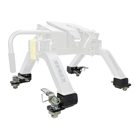
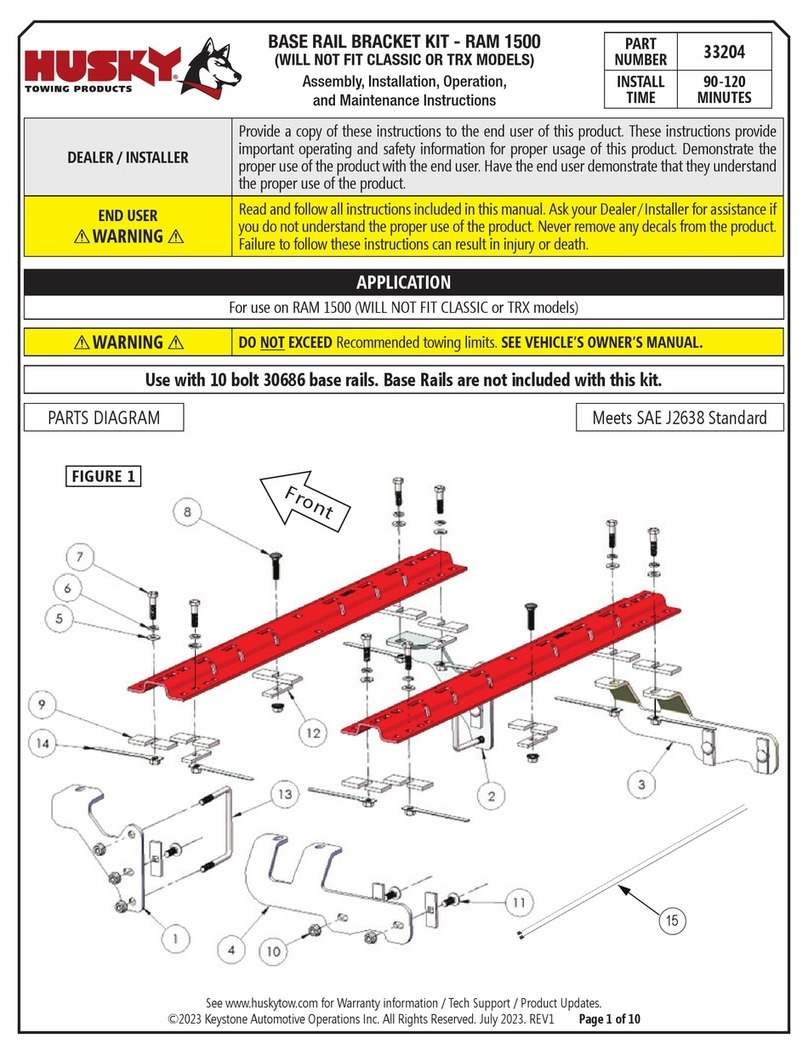
Kit, Base Rail Bracket Part # 31853
.
Dealer /
Installer: Provide a copy of these Instructions to the end user of this product. These Instructions provide important
operating and safety information for proper usage of this product. Demonstrate the proper use of the
product with the end user. Have the end user demonstrate that they understand the proper use of the
product.
End User: Read and follow all instructions included in this manual. Ask your Dealer / Installer for assistance if you
do not understand the proper use of the product. Never remove any decals from the product.
APPLICATION: 2011 - 2017 Chevrolet & GMC Silverado & Sierra 2500 & 3500 HD Pick-ups
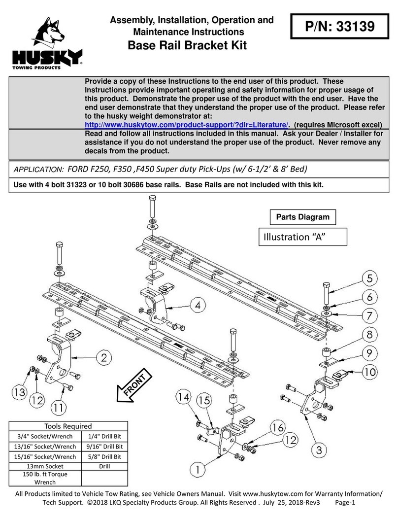
Complete Parts List
ITEM NO. Description QTY.
1 DRIVER SIDE FRONT "L" BRACKET 1
2 DRIVER SIDE REAR "L" BRACKET 1
3 PASSENGER SIDE FRONT "L" BRACKET 1
4 PASSENGER SIDE REAR "L" BRACKET 1
5 5/8" -11 CLIP NUT 4
6 1" SPACER TUBE 4
7 1/4" SPACER PLATE 4
8 PULL WIRE FOR 5/8"-11 THREADED BOLT 2
9 5/8" -11 GRADE 5 HEX NUT, CLEAR 8 Tools Required
10 Ø5/8" X Ø1.079" LOCK WASHER, CLEAR 8 3/4" Socket & Wrench
11 Ø5/8 X Ø1-3/4 FLAT WASHER, CLEAR 8 15/16" Socket & Wrench
12 5/8"-11 BOLT AND ANTI-ROTATION PLATE 8 5/8" Drill Bit
13 Ø5/8" X Ø1.079" LOCK WASHER, BLACK 4 11/16" Drill Bit
14 Ø5/8 X Ø1-3/4 FLAT WASHER, BLACK 4 Torque Wrench
15 5/8"-11 X 3.25" GRADE 5 HEX BOLT, BLOT 4 Safety Glasses
(Can be used with 4 Bolt Rails
#31323 or 10 Bolt Rails #30686)
WARNING! Never exceed the towing
ca
p
acit
y
of the tow vehicle.
CenterBoltKit32059(soldseparately)
mustbeusedwhentowingwitha26K
hitch,GooseNeck,orManeuvering
S
y
stem.
CAUTION: Do not install base rails over plastic bed
liners. Plastic bed liners must be cut out of the way.
Rails may be installed on spray in liners. Consult
spray liner installer for recommended curing time.
Base Rails Not Included
All Products limited to Vehicle Tow Rating, see Vehicle Owners Manual. See www.huskytow.com for Warranty Information / Tech
Support / Product Updates. ©2017 DTS Mfg. All Rights Reserved. April 5, 2017 REV14. Page 2 of 8
Figure 1
GM 2500 FRAME IS SHOWN, GM 3500 FRAME HAS OVER LOAD
SPRINGS AND BRACKETS THAT ARE NOT SHOWN.
If using 10 Bolt Rails #30686
31-1/16” Long Bed Dimension
26-3/16” Short Bed Dimension
For #31323 4 Bolt Rails

All Products limited to Vehicle Tow Rating, see Vehicle Owners Manual. See www.huskytow.com for Warranty Information / Tech
Support / Product Updates. ©2017 DTS Mfg. All Rights Reserved. April 5, 2017 REV14. Page 3 of 8
1. Place the two bed rails across the truck bed between the wheel wells. Position the 5th wheel uprights between the bed rails
so that the tabs in the base of each upright will fit into the slots in the ends of the bed rails. Secure the uprights in place
with the rail hitch pins and hair pins supplied with the 5th wheel installation kit. Securely attach 5th wheel cross member to
uprights.
2. Position the bed rail assembly in truck bed as shown in Figure 2. When hitch is correctly positioned in the bed and the bed
rails are parallel, mark four attachment points on the truck bed using the 5/8” square holes indicated on the layout in
Figure 2. Check below the bed before drilling holes to see that all wiring, brake lines or other obstructions are moved out
of the way and will not be contacted by the drill. Move the hitch assembly out of the way and drill four 5/8” diameter
attachment holes down through the bed at the previously marked points.
3. Reposition the bed rails in the bed so that the square 5/8” hole in the end of each rail is lined up over the drilled holes.
Place item #6 (1” spacer tube) under ends of each bed rail, in line with the drilled holes as shown on Figure 3.
4. If the bed corrugation above the frame is UP, leaving a space above the frame bracket, place item #7 (spacer plate) in the
bed, under the base rail as shown on Figure 4.
5. If wheel well is lined with a plastic liner that covers the frame, then cut out enough of the liner to expose the frame for
bracket installation.
6. Place item #13 (lock washer) and item #14 (flat washer) onto item #15 (5/8" hex bolt) and then insert into 4 drilled holes
through the base rails.
Base Rail
Item #6
Truck Bed
Item #7 Under the base rail
Item #7 Under the corrugation
Item #7
Base Rail Bed
Corrugation
Bracket
Bed
Corrugation
Fi
g
ure: 2
Fi
g
ure: 3

All Products limited to Vehicle Tow Rating, see Vehicle Owners Manual. See www.huskytow.com for Warranty Information / Tech
Support / Product Updates. ©2017 DTS Mfg. All Rights Reserved. April 5, 2017 REV14. Page 4 of 8
7. Position item #1 (DS Front "L" Bracket) and item #2 (DS Rear "L" Bracket) up against the outer surface of the truck
frame with the long slotted part of the bracket positioned over the frame and under the bed and guide the 5/8" hex bolts
that were installed in step 6 through the long slots in the brackets. Brackets are marked with a DSF for driver side front or
DSR for driver side rear to ensure brackets are placed in the correct position of the frame. Thread item #5 (Clip Nut 5/8-
11) onto end of item #15 (5/8-11 Hex Head Bolt) until all the long slotted portion of the brackets come in contact with the
underside of the bed floor. See Figure 4 & 4.1.
8. Press the frame brackets up against the truck frame until they come in contact and stop. Look through the holes
in the frame brackets and make sure the holes in the frame are in line, you may have to loosen the 5/8" hex bolts
some.
FR
ON
T
DRIVER SIDE SHOWN.
Use this hole in bracket as a guide to drill a
11/16" diameter hole through frame. This
location on passenger side too.
FRONT OF VEHICLE
VEHICLE FRAME REMOVED TO CLARIFY INSTALLATION
DRIVER SIDE SHOWN
FIGURE 4
5
1
FIGURE 4.1

All Products limited to Vehicle Tow Rating, see Vehicle Owners Manual. See www.huskytow.com for Warranty Information / Tech
Support / Product Updates. ©2017 DTS Mfg. All Rights Reserved. April 5, 2017 REV14. Page 5 of 8
9. Install item #12 (5/8 bolt and anti-rotation plate), item #11 (5/8 flat washer), item #10 (lock washer), item #9 (5/8 hex nut)
as follows:
Insert pull wire through hole in bracket.
Guide pull wire coils through hole on inside of frame.
Bend end of pull wire to prevent from going through slot in bracket and hole in frame.
Thread item #12 (bolt and anti-rotation plate) in to item
#8 (pull wire). Then pull other end of pull wire gently
while guiding Bolt and anti-rotation plate through the
hole on inside of frame.

All Products limited to Vehicle Tow Rating, see Vehicle Owners Manual. See www.huskytow.com for Warranty Information / Tech
Support / Product Updates. ©2017 DTS Mfg. All Rights Reserved. April 5, 2017 REV14. Page 6 of 8
Continue to retrieve pull wire until bolt appears through slot in bracket, carefully un-thread pull wire from bolt
and place item #11 (flat washer), item #10 (lock washer) and item #9 (5/8 hex nut) on bolt and finger tighten only
at this time.
10. Repeat step 9 for the remaining slot in the driver side bracket, driver side rear bracket, passenger side front
and rear brackets.
11. Tighten each 5/8” bed rail attachment bolt to 150 ft-lbs. torque. Failure to tighten bolts as described may result
in fastener loss or failure. DO NOT apply torque to the nut portion of the clip nuts (#5). You will DAMAGE it.
12. Check each rail hitch pin for freedom of movement in the bed rail connection before tightening the 5/8” bolts
and nuts. Adjust uprights, if necessary, by placing shim 31582 or 30243 between the upright and the cross
member to obtain free pin movement. See Figure 5. Shims 31582 & 30243 sold separately.
Figure 5

All Products limited to Vehicle Tow Rating, see Vehicle Owners Manual. See www.huskytow.com for Warranty Information / Tech
Support / Product Updates. ©2017 DTS Mfg. All Rights Reserved. April 5, 2017 REV14. Page 7 of 8

All Products limited to Vehicle Tow Rating, see Vehicle Owners Manual. See www.huskytow.com for Warranty Information / Tech
Support / Product Updates. ©2017 DTS Mfg. All Rights Reserved. April 5, 2017 REV14. Page 8 of 8
Warranty Terms:
5 Year Limited Warranty:
This warranty applies solely to Husky 5th Wheel Installation Kit manufactured by DTS Mfg. for Husky Towing
Products.
Husky Towing Products and DTS Mfg. make no guarantees or warranties for products not manufactured by
DTS Mfg. Such products are covered solely under any applicable warranty of the manufacturer. It is always
recommended that the operating instructions and guarantee instructions provided by the manufacturer are
followed.
DTS Mfg. warrants its products to be free from manufacturing and material defects to the original purchaser
for the length of warranty stated above from the date of retail purchase. If any products are found to have a
manufacturing or material defect, the product will be replaced or repaired at the option of Husky Towing
Products and DTS Mfg. with proof of purchase by the original purchaser. The original purchaser shall pay all
transportation and shipping costs associated with the return of the defective product and the defective
product shall become the property of DTS Mfg.
The Warranty applies to DTS Mfg. products used for individual and recreational purposes. Commercial
usage of the DTS Mfg. products limits the warranty to 90-days from date of purchase.
The Warranty applies only to DTS Mfg. products which are found to be defective in manufacturing or
material. This warranty does not apply to normal wear and tear of to the finished placed on DTS Mfg.
products.
Husky Towing Products and DTS Mfg. are not responsible for any labor costs incurred for removal or
replacement of the defective product.
Husky Towing Products and DTS Mfg. are not responsible for repair or replacement of any product under the
limited warranty where the product was improperly installed, misapplied, altered, abused, neglected,
overloaded, misused or damaged as a result of an accident, including any use of the product not in
accordance with all product operating and safety instructions.
Without limiting the generality of the foregoing, Husky Towing Products and DTS Mfg. shall under no
circumstances be liable for any incidental or consequential loss or damage whatsoever arising out of, or in
any way relating to any such breach of warranty or claimed defect in, or non-performance of the products.
Some states do not allow the exclusion or limitation of incidental or consequential damages, so the above
exclusion or limitation may not apply to you.
This limited warranty gives you specific legal rights, and you may also have other rights that vary from state
to state.
Table of contents
Other Husky Automobile Accessories manuals

Husky
Husky 10-16K Glider User manual

Husky
Husky 31313 Assembly instructions

Husky
Husky 33204 User manual

Husky
Husky 33100 User manual

Husky
Husky 33222 User manual

Husky
Husky 33001 User manual

Husky
Husky 32998 User manual

Husky
Husky RH 34715 User manual

Husky
Husky 09421 User manual

Husky
Husky 34715 User manual
Popular Automobile Accessories manuals by other brands

Front Runner
Front Runner SLIMLINE II Fittings guide

Phoenix Contact
Phoenix Contact CHARX T2HBI 1AC32DC125 Series Installation notes for electricians

Prorack
Prorack K162 Fitting instructions

Ranger design
Ranger design 5045 installation guide

Hyundai
Hyundai L0F62 AU000 Quick reference guide

Whispbar
Whispbar K390 Fitting instructions