Husqvarna X-COM R Instruction manual

Workshop manual
X-COM R
English
893 - 001 -

Contents
1 Introduction
1.1 Product information................................................ 3
1.2 Document description............................................ 3
1.3 Revisions................................................................3
1.4 Safety..................................................................... 3
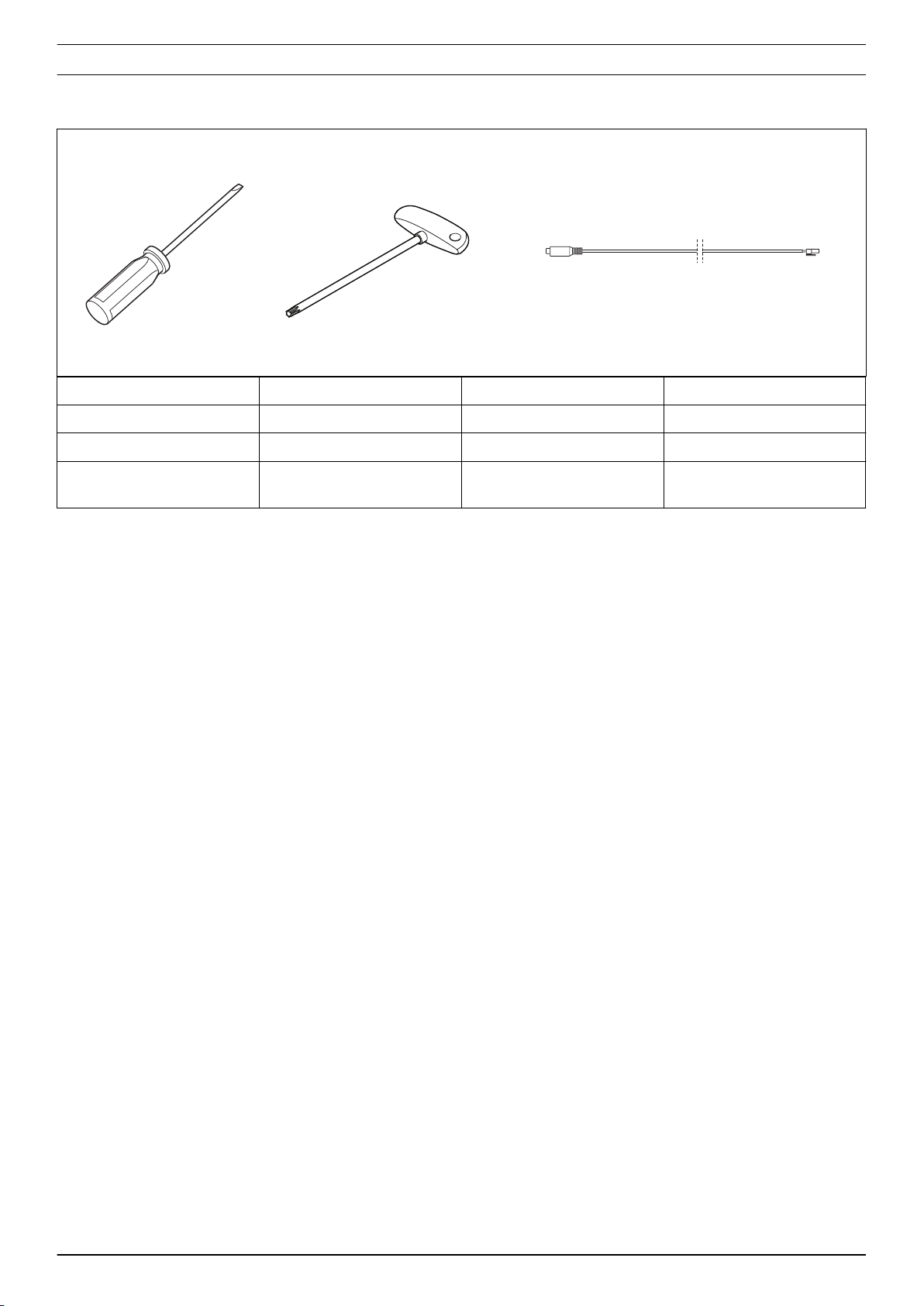
1.5 Servicing tools........................................................3
2 Safety
2.1 Safety definitions....................................................4
2.2 General safety instructions.....................................4
2.3 Symbols on the product......................................... 4
2.4 Special safety instructions......................................4
3 Prepare and do servicing on the product
3.1 Life cycle and discharge of the battery...................5
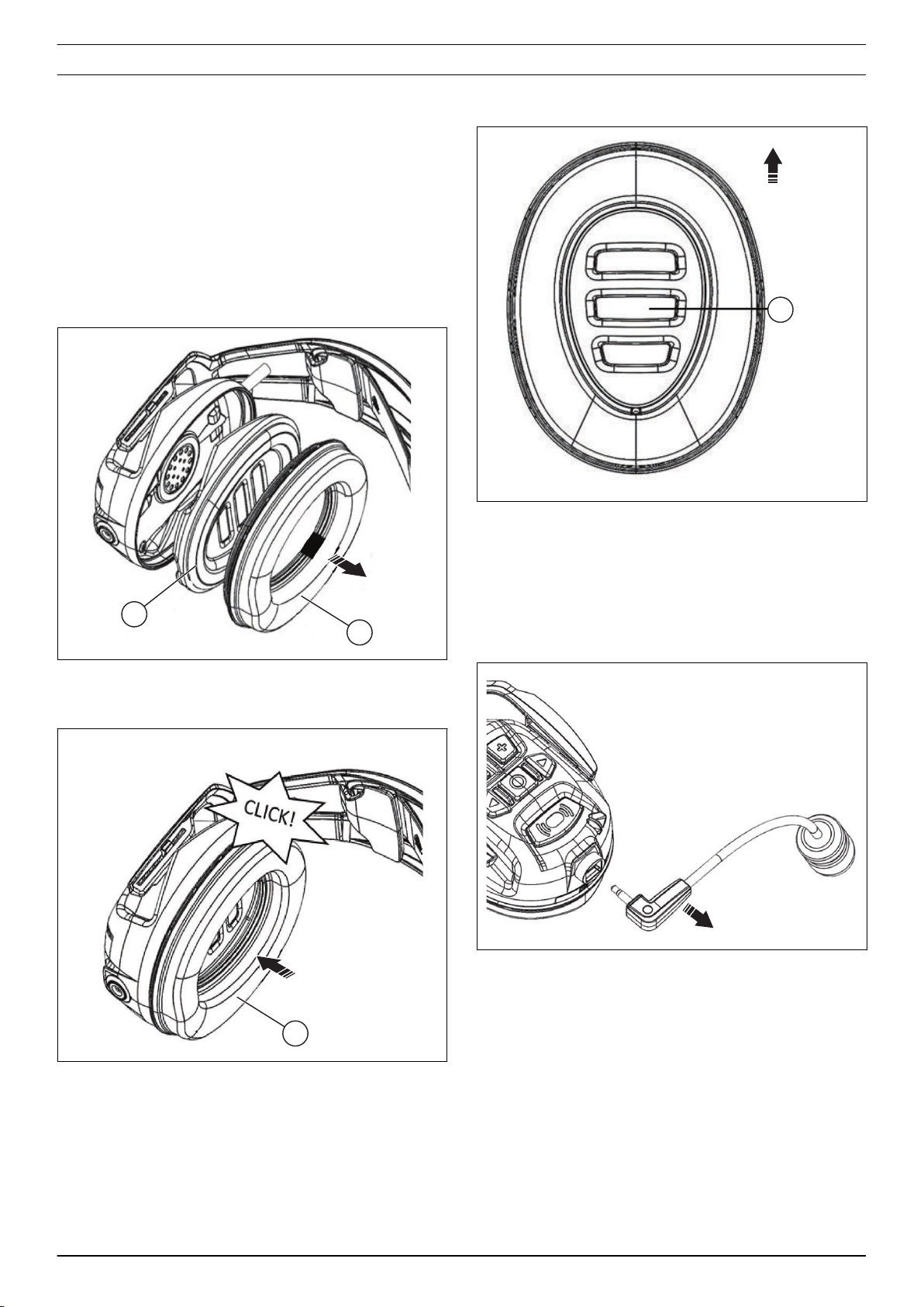
3.2 To replace the hygiene kit...................................... 5
3.3 To remove and install the boom microphone......... 5
4 Servicing data
4.1 Servicing data HP310-1......................................... 6
4.2 Servicing data HP310-2......................................... 7
5 Servicing tools
5.1 Servicing tools .......................................................8
6 Function overview
6.1 Product serial number............................................ 9
7 Repair instructions
7.1 To clean and examine the product parts..............10
7.2 To remove and install the headband....................10
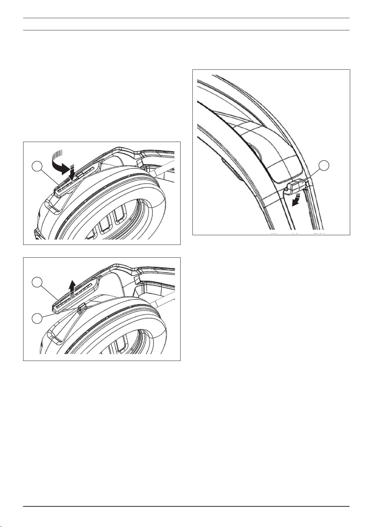
7.3 The cable clip....................................................... 10
7.4 The earmuffs........................................................ 11
7.5 The strain relief cable...........................................14
7.6 The microphone connector.................................. 15
7.7 The DC connector................................................ 16
7.8 The loudspeakers.................................................16
7.9 The microphone................................................... 17
7.10 The battery......................................................... 19
7.11 The push button adapter.................................... 20
7.12 The wind screen.................................................20
7.13 To install a software update .............................. 21
8 Troubleshooting
8.1 Troubleshooting of the product............................ 22
9 Wiring diagram
9.1 Wiring diagram..................................................... 24
2893 - 001 -

1 Introduction
1.1 Product information
X-COM R is available with a headband or helmet.
1.2 Document description
This manual gives a full description of how to do
maintenance and repair on the product. It also gives
safety instructions that the personnel must obey.
1.3 Revisions
Changes to the product can cause changes to the
maintenance work and spare parts. Separate
information is sent out for each change.
Read the manual together with all received information
about changes to maintenance and spare parts for the
product.
1.4 Safety
WARNING: All personnel that repair or do
servicing on the product must read and
understand the safety instructions in this
workshop manual.
1.5 Servicing tools
The manual gives information about necessary servicing
tools. Always use original tools from Husqvarna.
893 - 001 - Introduction - 3

2 Safety
2.1 Safety definitions
Warnings, cautions and notes are used to point out
specially important parts of the manual.
WARNING: Used if there is a risk of injury or
death for the operator or bystanders if the
instructions in the manual are not obeyed.
CAUTION: Used if there is a risk of damage to
the product, other materials or the adjacent area
if the instructions in the manual are not obeyed.
Note: Used to give more information that is necessary in
a given situation.
2.2 General safety instructions
WARNING: Apply a new warning label if a
warning symbol on the product is damaged or
missing.
2.3 Symbols on the product
Only use Husqvarna battery. Obey the safety
instructions that are given for the battery and charger
cable.
The product agrees with the applicable
EC directives.
2.4 Special safety instructions
2.4.1 Battery
WARNING: Do not use accessories that are not
approved by the manufacturer. Do not do
changes that are not approved by the
manufacturer.
WARNING: Always use original spare parts and
accessories.
4 - Safety 893 - 001 -

3 Prepare and do servicing on the product
3.1 Life cycle and discharge of the battery
During long-term storage, charge the battery at an
interval of 6 months to prevent discharge of the battery.
Discharge can decrease the life cycle of the battery.
3.2 To replace the hygiene kit
The hygiene kit must be replaced when necessary or
minimum with a 6 months interval. Use the correct
hygiene kit from Husqvarna .
1. Remove the sealing ring (A) and foam rubber insert
(B).
B
A
2. Install the new foam rubber insert and the new
sealing ring. Make sure that the bulge (C) is in the
correct position.
C
3. Make sure that the foam rubber insert is installed as
shown (D).
D
3.3 To remove and install the boom
microphone
The boom microphone can make sound quality better in
phone calls in an environment with noise.
1. Pull out the boom microphone from the microphone
input.
2. Install in the opposite sequence
893 - 001 - Prepare and do servicing on the product - 5

4 Servicing data
4.1 Servicing data HP310-1
The tightening torque for the screws is 0.3 – 0.5 Nm.
6 - Servicing data 893 - 001 -

4.2 Servicing data HP310-2
The tightening torque for the screws is 0.3 – 0.5 Nm.
893 - 001 - Servicing data - 7

5 Servicing tools
5.1 Servicing tools
12 3
Item Description Use for Art. no
1 Screw driver, Flat Headband N/A
2 T-handle torx T7 Screws with torx head N/A
3 USB to TTL Serial Cable
(3,3V)
For Bluetooth Headset
HP310
597 37 31-01
8 - Servicing tools 893 - 001 -

6 Function overview
6.1 Product serial number
• The serial number is given by the scannable code
on the label (A) behind the foam rubber insert on the
left earmuff on the battery side.
A
• The type plate is on right earmuff (B).
B
893 - 001 - Function overview - 9

7 Repair instructions
7.1 To clean and examine the product parts
• Clean and examine all parts fully. You find more
instructions in the chapter for each part if special
tools or procedures are necessary.
• Replace damaged or defective parts.
• Always use original spare parts.
7.2 To remove and install the headband
1. Remove the cable clip. Refer to
To remove the cable
clip on page 10
.
2. Use a screwdriver to open the slot (A).
A
3. Remove the headband (B) from the pin (C).
B
C
4. Install in the opposite sequence.
7.3 The cable clip
7.3.1 To remove the cable clip
• Remove the cable clip (A).
A
10 - Repair instructions 893 - 001 -

7.3.2 To install the cable clip
1. Attach the cable clip (A) to the headband (B).
A
B
2. Push the cable clip (C) until you hear a click sound
and the cable clip locks in position.
C
7.4 The earmuffs
7.4.1 To disassemble the right earmuff
CAUTION: Be careful when you do work on the
wires. The wires can easily be damaged.
1. Make a note of how the cables and components are
installed when you disassemble the earmuff.
2. Remove the earmuff from the headband. Refer to
To
remove and install the headband on page 10
.
3. Remove the hygiene kit. Refer to
To replace the
hygiene kit on page 5
.
4. Remove the 4 screws (A) and the inner earmuff (B).
A
B
5. Remove the 4 screws (C).
E
C
DF
6. Lift up the circuit board (D).
7. Loosen the strain relief (E) and the microphone
connector (F).
893 - 001 - Repair instructions - 11

8. Disconnect the connectors for the strain relief (G),
the microphone (H), the microphone connector (I)
and the loudspeaker (J).
G
H
I
J
7.4.2 To disassemble the left earmuff
CAUTION: Be careful when you do work on the
wires. The wires can easily be damaged.
1. Make a note of how the cables and components are
installed when you disassemble the earmuff.
2. Remove the earmuff from the headband. Refer to
To
remove and install the headband on page 10
.
3. Remove the hygiene kit. Refer to
To replace the
hygiene kit on page 5
.
4. Remove the 4 screws (A) and the inner earmuff (B).
A
B
5. Loosen the strain relief (C) and the DC connector
(D).
CD
6. Disconnect the connectors for the strain relief cable
(E), the loudspeaker (F), the microphone (G), the
power connector (H) and the battery (I).
E
F
G
H
I
12 - Repair instructions 893 - 001 -

7.4.3 To assemble the right earmuff
1. Connect the connectors for the strain relief cable
(G), microphone (H), microphone connector (I) and
loudspeaker (J).
A
B
C
D
2. Install the circuit board (E) with the 4 screws (F).
G
F
EH
3. Install the strain relief (G) and the microphone
connector (H).
4. Install the inner earmuff (I) with the 4 screws.
I
5. Install the foam rubber insert (J) and attach the
sealing ring (K).
J
K
6. Attach the earmuff to the headband. Refer to
To
remove and install the headband on page 10
.
893 - 001 - Repair instructions - 13

7.4.4 To assemble the left earmuff
1. Connect the connectors for the strain relief cable
(A), the loudspeaker (B), the microphone (C), the
power connector (D) and the battery (E).
A
B
C
D
E
2. Install the strain relief cable (F) and the DC
connector (G).
FG
3. Install the inner earmuff (H) with the 4 screws (I).
I
H
4. Install the foam rubber insert (J) and attach the
sealing ring (K).
J
K
5. Attach the earmuff to the headband. Refer to
To
remove and install the headband on page 10
.
7.5 The strain relief cable
7.5.1 To disconnect the strain relief cable
1. Disassemble the right earmuff. Refer to
To
disassemble the right earmuff on page 11
.
2. Disassemble the left earmuff. Refer to
To
disassemble the left earmuff on page 12
.
3. Disconnect the strain relief cable (A) from the circuit
board.
A
7.5.2 To install the strain relief cable
Make sure that the strain relief cable has the correct
length before it is installed.
• Cable length for headband: 400 mm.
• Cable length for helmet: 850 mm.
14 - Repair instructions 893 - 001 -

1. Make sure to connect the correct end of the strain
relief cable (A) to the circuit board. The 10-pin end
must be connected to the right earmuff and the 9-pin
end must be connected to the left earmuff.
A
2. Assemble the left earmuff. Refer to
To assemble the
left earmuff on page 14
.
3. Assemble the right earmuff. Refer to
To assemble
the right earmuff on page 13
.
7.6 The microphone connector
7.6.1 To disconnect the microphone connector
1. Disassemble the right earmuff. Refer to
To
disassemble the right earmuff on page 11
.
2. Disconnect the microphone connector cable from
the circuit board in position (A).
A
7.6.2 To connect the microphone connector
1. Connect the microphone connector cable to the
circuit board in position (A). Put the cable in a loop
as shown in the illustration.
A
2. Make sure that the microphone connector (B) is
installed in the correct position. Put in the
microphone connector (B) in the earmuff housing.
B
3. Assemble the right earmuff. Refer to
To assemble
the right earmuff on page 13
.
893 - 001 - Repair instructions - 15

7.7 The DC connector
7.7.1 To disconnect the DC connector
1. Disassemble the left earmuff. Refer to
To
disassemble the left earmuff on page 12
.
2. Disconnect the DC connector cable (A) from the
circuit board.
A
7.7.2 To connect the DC connector
1. Connect the DC connector (A) on the circuit board
and put the wire in a loop (B) as shown in the
illustration.
A
B
2. Assemble the left earmuff. Refer to
To assemble the
left earmuff on page 14
.
7.8 The loudspeakers
7.8.1 To remove the loudspeaker
Note: Make sure that the loudspeaker and the sealing
are in the correct position.
1. Make a note of how the cables and components are
installed before you remove the loudspeaker.
2. Disassemble the right earmuff. Refer to
To
disassemble the right earmuff on page 11
.
3. Disassemble the left earmuff. Refer to
To
disassemble the left earmuff on page 12
.
4. Disconnect the loudspeaker cables and remove the
loudspeaker from the circuit board.
16 - Repair instructions 893 - 001 -

7.8.2 To install the loudspeakers
CAUTION: The wires are easily damaged when
you install the loudspeakers.
1. Right earmuff: Attach the loudspeaker on the circuit
board as shown in the illustration. Connect the
loudspeaker cable to the position (A). Install the
cable (B) as shown in the illustration.
B
A
2. Left earmuff: Assemble the loudspeaker on the
circuit board as shown in the illustration. Connect
the loudspeaker cable to the position (C). Install the
cable (D) as shown in the illustration.
E
D
3. Install the loudspeakers and the sealing rings. Make
sure that the flat side of the sealing ring (F) is
installed against the flat side (G) of the
loudspeakers.
F
G
4. Assemble the right earmuff. Refer to
To assemble
the right earmuff on page 13
.
5. Assemble the left earmuff. Refer to
To assemble the
left earmuff on page 14
.
7.9 The microphone
7.9.1 To remove the microphone
1. Make sure that the microphone and the sealing ring
are in the correct position.
2. Make a note of how the cables and components are
installed before you remove the microphone.
3. Disassemble the left earmuff. Refer to
To
disassemble the left earmuff on page 12
.
4. Disassemble the right earmuff. Refer to
To
disassemble the right earmuff on page 11
.
893 - 001 - Repair instructions - 17

5. Right earmuff: Disconnect the microphone connector
(A) from the circuit board.
A
6. Left earmuff: Disconnect the microphone connector
(B) from the circuit board.
B
7. Remove the microphone (C) and wind filter (D).
C
D
7.9.2 To install the microphone
1. Assemble the wind filter (A).
A
2. Put the rubber sealing boot (B) on the microphone.
B
3. Push the microphone rubber boot and make sure it
aligns with the top of seat in earmuff (C).
C
18 - Repair instructions 893 - 001 -

4. Right earmuff: Connect the microphone connector
(D). Put the cable as shown in the illustration.
D
5. Left earmuff: Connect the microphone connector (E).
Put the cable as shown in the illustration.
E
6. Assemble the right earmuff. Refer to
To assemble
the right earmuff on page 13
.
7. Assemble the left earmuff. Refer to
To assemble the
left earmuff on page 14
.
7.10 The battery
7.10.1 To replace the battery
1. Disassemble the left earmuff. Refer to
To
disassemble the left earmuff on page 12
.
2. Disconnect the battery connector.
3. Remove the 4 screws (A) and carefully remove the
circuit board (B).
A
B
893 - 001 - Repair instructions - 19

4. Remove the battery (C) and the foam sheet (D).
C
D
5. Install in the opposite sequence. Make sure that you
put the battery cable as shown in the illustration.
7.11 The push button adapter
7.11.1 To remove and install the push button
adapter
1. Disassemble the right earmuff. Refer to
To
disassemble the right earmuff on page 11
.
2. Remove the push button adapter (A).
A
3. Install in the opposite sequence.
7.12 The wind screen
7.12.1 To remove and install the wind screen
1. Remove the O-ring (A).
A
B
C
2. Remove the wind screen (B) from the boom
microphone (C).
3. Install in the opposite sequence.
20 - Repair instructions 893 - 001 -
Other manuals for X-COM R
2
Table of contents
Other Husqvarna Safety Equipment manuals

Husqvarna
Husqvarna PE 10J SmartGuard User manual

Husqvarna
Husqvarna PE 10H User manual

Husqvarna
Husqvarna Prusik Eye-n-Eye 8 mm User manual

Husqvarna
Husqvarna 5776165-11 User manual

Husqvarna
Husqvarna 910 Specification sheet

Husqvarna
Husqvarna Climbing Rope 11.5 mm User manual

Husqvarna
Husqvarna 198 User manual

Husqvarna
Husqvarna X-SYNC User manual

Husqvarna
Husqvarna X-COM Active User manual

Husqvarna
Husqvarna 5791167-03 User manual