manuals.online logo
Brands
  1. Home
  2. •
  3. Brands
  4. •
  5. Hydor
  6. •
  7. Fan
  8. •
  9. Hydor HV800 User manual

Hydor HV800 User manual

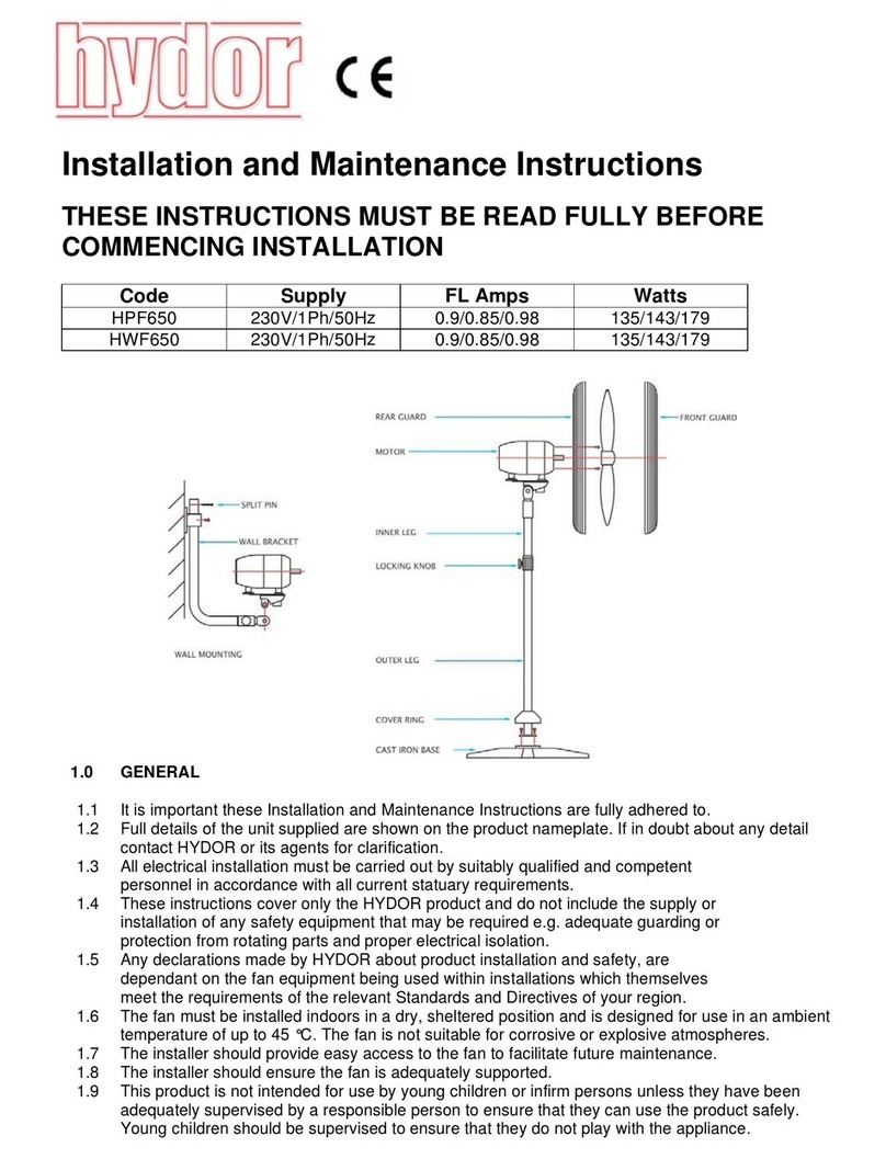
HV Inst Issue 2: 18.06.15
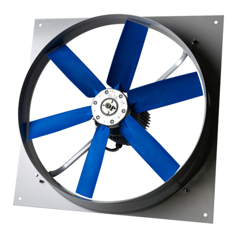
Installation and Maintenance Instructions.
THESE INSTRUCTIONS MUST BE READ FULLY BEFORE COMMENCING INSTALLATION.
Owner / installer: The life of this apparatus and its eciency will be increased if
its use and maintenance is carried out in accordance with these instructions and
current statutory requirements. The installation and initial adjustments should be
carried out by a qualified and competent technician. Hydor Limited should be
consulted before substituting or fitting parts from another manufacturer. It is the
responsibility of the installer to verify that the installation is in accordance with
the following standards and the owner is given the current User’s Manual.
Any modifications to the fan or its installation, even the smallest
modification, change or elimination of security components or pieces that
influence the eciency or loss of ventilation, will result in the CE Certification
and Hydor’s warranty being cancelled.
Single Phase
Model Speed
r/min
Supply
V-Ph-Hz
Power
kw
FLC
Amps
Start
Amps
Blade
Mattl.
Weight
kg
Weight
kg incl.
Louvre
HV800 530 230-1-50 0750 4.5 14.3 st.st 31 44
HV1000 600 230-1-50 0750 5.4 14.9 st.st 40 50
HV1250 410 230-1-50 1,100 7. 2 25.7 st.st 50 70
HV1250A 425 230-1-50 1,100 7.5 25.7 ali. 50 70
HV1250 425 230-1-50 1,500 8.4 29.5 st.st 52 72
HV1500 360 230-1-50 1,500 9.4 33.0 st.st 55 85
HV2000 375 230-1-50 1,500 10.0 35.0 st.st 75 100
HV Belt Drive Fan
incorrect
correct, minimum height 5mm
HV Inst Issue 2: 18.06.15HV Inst Issue 2: 18.06.15
Three Phase
Model Speed
r/min
Supply
V-Ph-Hz
Power
Watts
FLC
Amps
Start
Amps
Blade
Mattl.
Weight
Kg
Weight
Kg incl.
Louvre
HV800 530 400-3-50 0750 2.0 5.9 st.st 32 44
HV1000 600 400-3-50 0750 2.6 7.8 st.st 40 50
HV1250 410 400-3-50 1,100 2.89 8.7 st.st 50 70
HV1250A 425 400-3-50 1,100 2.89 8.7 ali. 50 70
HV1250 425 400-3-50 1,500 3.2 9.6 st.st 52 72
HV1500 360 400-3-50 1,500 3.6 10.8 st.st 55 85
HV2000 375 400-3-50 1,500 3.8 12.5 st.st 75 100
1. Description
1.1 It is important these Installation and Maintenance Instructions are fully
adhered to.
1.2 Full details of the unit supplied are shown on the product nameplate. If in
doubt about any detail contact Hydor or its agents for clarification.
1.3 All electrical installations must be carried out by suitably qualified and
competent personnel in accordance with all current statutory
requirements.
1.4 These instructions cover only the Hydor product and do not include the
supply or installation of any safety equipment that may be required e.g.
proper electrical isolation.
1.5 Any declarations made by Hydor about product installation and safety,
are dependent on the fan unit being used within installations which
themselves meet the requirements of the relevant Standards and
Directives of your region.
1.6 The fan unit is designed for use in an ambient temperature of up to 50°C
and 95% relative humidity. The fan unit is not suitable for corrosive or
explosive atmospheres.
1.7 The installer should provide easy access to the fan to facilitate future
maintenance.
1.8 The installer should ensure the fan unit is mounted slightly tilted forward
at the top towards the outside of the building and adequately supported.
Holes are provided in the base of the casing to assist drainage.
1.9 This product is not intended for the use of young children or infirm
persons unless they have been dequately supervised by a responsible
person to ensure that they can use the product safely. Young children
should be supervised to ensure that they do not play with the appliance.
WARNING The fan unit must be isolated from the power supply during
installation and maintenance. The fan must be earthed in accordance
with the local regulations.
2. Installation
2.1 Upon receipt, the fan unit should be visually inspected to check for any
damage. Ensure that the impeller is free to rotate.
2.2 If there are any queries concerning the fan unit, HYDOR should be
contacted prior to installation. air space, in front and behind the fan. A
minimum of 2 metres is required.
2.3 If the unit is to be suspended, attach a chain to each eyebolt using
separate D shackles for each chain. Form a “V” using two chains [one pair
in front and one pair rear] and two small D shackles attached to one large
D shackle each. In some instances it will be beneficial to suspend the fan
leaning forward by adjusting the chains to direct the air downwards.
NOTE Chain and D-shackles are not provided. Ensure that chain used
will support weight of unit. Additionally, in some instances using long
chains may cause a pendulum eect to develop; an additional check
chain or rope will prevent this.
2.4 Where a fan is installed in a wall of the building, ensure that the access to
the terminal plate and panel is available. Secure the fan unit using angled
steel to fix to a surrounding wall.
NOTE Ensure the unit is installed square; failure to do so may result in
poor operation of the back-draught shutter blades.
2.5 Check the details on the motor rating plate to ensure that the correct
power supply (voltage, frequency).
2.6 Eyebolts are provided as extras; for units which are to be suspended.
2.7 Refer to the appropriate wiring diagram. Means for electrical
disconnection must be incorporated in the wiring installation in
accordance with the relevant wiring and electrical regulations. Ensure
that all earth connections are made and secure. Fuses/circuit breakers are
used to provide short circuit protection only. A starter panel with overload
protection must be fitted to protect the motor.
2.8 If the fan is being used through a speed control device, either electrically
or electronically, refer to the relevant control device instructions before
commencing installation.
HV Inst Issue 2: 18.06.15HV Inst Issue 2: 18.06.15
3. Operation
3.1 Before power is supplied to the unit, check that the wiring is correct as
per the fan connection diagram and control instructions [If fitted].
3.2 At initial start-up, check that the impeller rotation and airflow direction is
correct.
3.3 Check that the motor amperage does not exceed the nameplate rating at
full speed and the electrical switch-gear is correctly sized using Hydor
technical information.
4. Fan Maintenance
4.1 Inspection of the fan unit at least every 6 months is recommended to
ensure that the motor, fan blades and supporting guards, are clean. Any
build-up of dust deposits should be removed using a non-abrasive
cleaner.
4.2 All fastenings should be checked for tightness. In addition, all rotating
items should be checked.
4.3 Bearings are of the “sealed for life” variety and will not need a detail
inspection.
4.4 Belt tension should be checked after 2-3 days use (48-72 hours usage).
Allow 15-20mm deflection for the correct tension. Please note over
tensioning will dramatically aect the longevity of the unit.
WARNING Only a suitably qualified and competent person may carry
out maintenance after the electrical supply has been isolated. Particular
care must be taken when automatic switching controls are used.
ALL FANS COME PRE-WIRED,
WITH FLEXIBLE CABLE
W2
U1
U2
V1
V2
W1
N - BLUE
L - BROWN
220V TO 240V 1Ph
50 HZ SUPPLY
E - GREEN / YELLOW
L1 - BROWN
L2 - BLACK
L3 - GREY
380V TO 415V 3Ph 50Hz
SUPPLY
ALL FANS COMEPRE-WIRED,
WITH FLEXIBLE CABLE
W2
U1
U2
V1
V2
W1
E - GREEN / YELLOW
5. Wiring Diagrams
HV Inst Issue 2: 18.06.15HV Inst Issue 2: 18.06.15
Notes Notes
HV Inst Issue 2: 18.06.15
Guarantee
Hydor or its agents will, within a period of one year from the date of dispatch
from their works, at its option, replace any goods, which are proven to have
defects as a result of defective materials or workmanship. The goods must be
inspected by a Hydor ocial and if necessary returned, with a Returns Note
Number, carriage paid, for further examination.
Hydor Ltd
Hydor
Unit 8, Parkers Close, Downton Business Centre,
Downton, Salisbury, Wiltshire, SP5 3RB, UK
Tel: +44 (0) 1725 511422
Fax: +44 (0) 1725 512637
Email: info@hydor.co.uk
Web: www.hydor.co.uk
idealair group
Unit 1, Building 1, Sydney Corporate Park,
85 O’Riordan Street, Alexandria NSW 2015
Tel: +61 (02) 8073 3310
Fax: +61 (02) 8073 3320
Email: info@idealairgroup.com.au
AMS
11 Ingrid Road, Montague Gardens,
7442 Cape Town, Western Cape
Tel: +27 (0) 21 552 1077
Fax: +27 (0) 21 552 2797

This manual suits for next models

5

Other Hydor Fan manuals

Hydor HXSU450 User manual

Hydor

Hydor HXSU450 User manual

Hydor HPA250/2-1A Technical specifications

Hydor

Hydor HPA250/2-1A Technical specifications

Hydor HDSF500/6/1/230 User manual

Hydor

Hydor HDSF500/6/1/230 User manual

Hydor HV800 User manual

Hydor

Hydor HV800 User manual

Hydor HVFB User manual

Hydor

Hydor HVFB User manual

Hydor HXP45041 User manual

Hydor

Hydor HXP45041 User manual

Hydor HCF User manual

Hydor

Hydor HCF User manual

Hydor HPF650 User manual

Hydor

Hydor HPF650 User manual

Hydor HEB Technical specifications

Hydor

Hydor HEB Technical specifications

Hydor HXP EC User manual

Hydor

Hydor HXP EC User manual

Hydor HV Series User manual

Hydor

Hydor HV Series User manual

Hydor HVWC800 User manual

Hydor

Hydor HVWC800 User manual

Hydor HIMF100 User manual

Hydor

Hydor HIMF100 User manual

Popular Fan manuals by other brands

Create WINDLIGHT CURVE DC user manual

Create

Create WINDLIGHT CURVE DC user manual

LBA Home Appliance Boussole user manual

LBA Home Appliance

LBA Home Appliance Boussole user manual

Pichler LG 500 P-R Operating and installation instructions

Pichler

Pichler LG 500 P-R Operating and installation instructions

Sulion WIRE manual

Sulion

Sulion WIRE manual

Frico Elektra H Instruction

Frico

Frico Elektra H Instruction

Monte Carlo Fan Company 5WS52XXD-L Series installation instructions

Monte Carlo Fan Company

Monte Carlo Fan Company 5WS52XXD-L Series installation instructions

Momax AIRY 360 instruction manual

Momax

Momax AIRY 360 instruction manual

Rowenta Turbo Silence VU5550 quick start guide

Rowenta

Rowenta Turbo Silence VU5550 quick start guide

Hunter Hunter Ceiling fans installation manual

Hunter

Hunter Hunter Ceiling fans installation manual

Solatube Solar Star RM 1500 installation instructions

Solatube

Solatube Solar Star RM 1500 installation instructions

S&P CACB-HP 12 instruction manual

S&P

S&P CACB-HP 12 instruction manual

Nortek PREEVA NEOS Installation and Servicing Manual

Nortek

Nortek PREEVA NEOS Installation and Servicing Manual

Field Controls 46115300 System manual

Field Controls

Field Controls 46115300 System manual

Europlast eextra EK Series instruction manual

Europlast

Europlast eextra EK Series instruction manual

Tate poweraire quad installation guide

Tate

Tate poweraire quad installation guide

Home Decorators Collection BROUGHTON YG671-BN Use and care guide

Home Decorators Collection

Home Decorators Collection BROUGHTON YG671-BN Use and care guide

Canarm GSF Series Operation instructions

Canarm

Canarm GSF Series Operation instructions

Vortice QBK HE SAL instruction manual

Vortice

Vortice QBK HE SAL instruction manual

manuals.online logo
manuals.online logoBrands
  • About & Mission
  • Contact us
  • Privacy Policy
  • Terms and Conditions

Copyright 2025 Manuals.Online. All Rights Reserved.