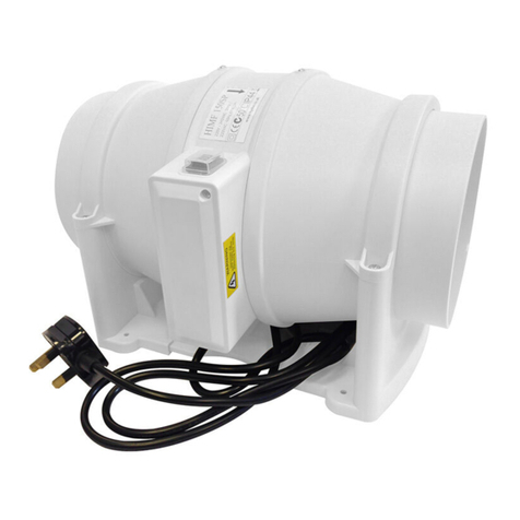
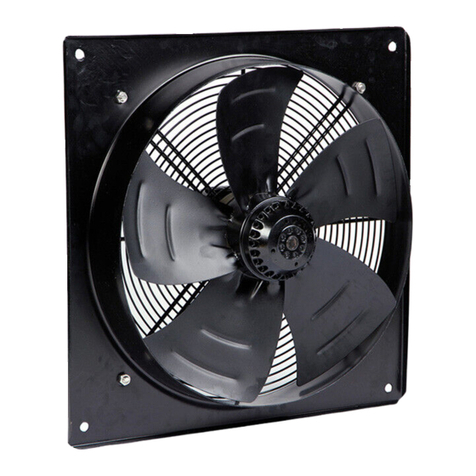
Hydor HXP45041 User manual

Installation and Maintenance Instructions.
THESE INSTRUCTIONS MUST BE READ FULLY BEFORE COMMENCING INSTALLATION.
Owner / installer: The life of this apparatus and its eciency will be increased if
its use and maintenance is carried out in accordance with these instructions and
current statutory requirements. The installation and initial adjustments should be
carried out by a qualified and competent technician. Hydor Limited should be
consulted before substituting or fitting parts from another manufacturer. It is the
responsibility of the installer to verify that the installation is in accordance with all
current statutory requirements and the owner is given the current User’s Manual.
Any modifications to the fan or its installation, even the smallest
modification, change or elimination of security components or pieces that
influence the eciency or loss of ventilation, will result in the CE Certification
and Hydor’s warranty being cancelled.
1. General
1.1 It is important these Installation and Maintenance Instructions are fully
adhered to.
1.2 Full details of the unit supplied are shown on the product nameplate. If in
doubt about any detail contact Hydor or its agents for clarification.
1.3 All electrical installation must be carried out by suitably qualified and
competent personnel in accordance with all current statutory
requirements.
1.4 These instructions cover only the Hydor product and do not include the
supply or installation of any safety equipment that may be required e.g.
adequate guarding or protection from rotating parts and proper electrical
isolation.
1.5 Any declarations made by Hydor about product installation and safety, are
dependant on the fan equipment being used within installations which
themselvesmeet the requirements of the relevant Standards and Directives
of your region.
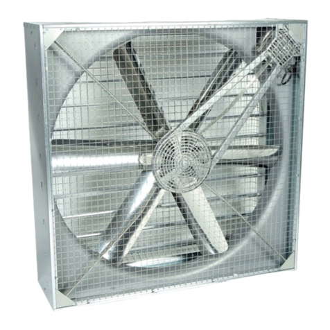
HXP Plate Fan
incorrect
correct, minimum height 5mm

1.6 The fan is designed for use in an ambient temperature of up to 70°C (fixed
speed), 55°C (speed controlled) and up to 95% relative humidity. The fan is
not suitable for corrosive or explosive atmospheres.
1.7 The installer should provide easy access to the fan to facilitate future
maintenance.
1.8 The installer should ensure the fan is adequately supported.
1.9 This product is not intended for use by young children or infirm persons
unless they have been adequately supervised by a responsible person to
ensure that they can use the product safely. Young children should be
supervised to ensure that they do not play with the appliance.
WARNING The fan must be isolated from the power supply during
installation and maintenance. The fan must be earthed in accordance
with the local regulations.
2. Installation
2.1 The HXP range of fans is normally supplied assembled. The single phase
units are supplied with the Capacitor loose.
2.2 Upon receipt, the fan equipment should be visually inspected to check for
any damage. Ensure that the impeller is free to rotate.
2.3 If there are any queries concerning the fan equipment, Hydor should be
contacted prior to the installation.
2.4 The fan must be securely mounted in the desired position to suit the
application. The fan can be mounted at any angle.
2.5 Check the details on the motor rating plate to ensure that the correct
power supply (voltage, frequency and phase) is available. An incorrect
power supply will lead to permanent damage to the fan motor.
2.6 Refer to the appropriate wiring diagram. Ensure that all earth connections
are made.
2.7 Means for electrical disconnection must be incorporated in the wiring
installation in accordance with the relevant wiring and electrical
regulations.
2.8 Precaution must be taken to locate the exhaust discharge terminal so as to
avoid the backflow of gases into the room from the open flue of gas or
other fuel burning appliances.
2.9 If the fan is being used through a speed regulation device, either
electrically or electronically. Please refer to the relevant control device
instructions.
3. Start-up
3.1 Before power is supplied to the unit, check that the wiring is correct as per
the fan connection diagram.
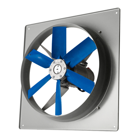
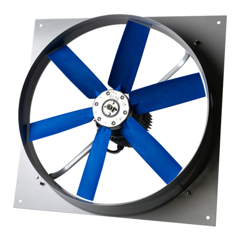
3.2 At initial start-up, check that impeller rotation and airflow direction is
correct.
3.3 Check that the motor amperage draw does not exceed the nameplate
rating.
4. Fan Maintenance
4.1 Inspection of the fan at least once every 12 months is recommended to
ensure that the motor, fan blades, and supporting guards, are clean. Any
build up of dust and deposits on the blades or guards should be removed
using a non-abrasive cleaner.
4.2 All fastenings should be checked for tightness. In addition, all rotating
items should be checked.
4.3 Bearings are of the ‘sealed for life’ type and will not need a detailed
inspection.
WARNING Only a suitably qualified and competent person may carry
out maintenance after the electrical supply has been isolated. Particular
care must be taken when automatic switching controls are used.
5. Wiring
5.1 Check that the fan unit supplied is suitable for the supply voltage and type
of fan being replaced.
5.2 Rem ove the terminal plate on the motor which will provide access to the
terminal connections. A suitably qualified and competent person should
carry out the electrical installation in accordance with the current
applicable regulations, in particular IEE 552-01-02/03. Particular attention
should be paid to the connections of the capacitor.

5.3 Single Phase
U2 - BLACK
220V TO 240V 1Ph 50Hz
SUPPLY
U3 - WHITE
U4 - BROWN
U1 - RED
Z1 - YELLOW
Z2 - BLUE
U3
U2
Z1
Z2
U1
U4
CAPACITOR
L - BROWN
N - BLUE
LINK
LINKLINK
CLOCKWISE ROTATION
U2 - BLA
CK
220V TO 240V 1Ph 50Hz
SUPPLY
U3 -
WHITE
U4 - BROWN
U1 - RED
Z2 -
YELLOW
Z1 - BLUE
U3
U2
Z2
Z1
U1
U4
CAPACITOR
L - BROWN
N - BLUE
LINK
LINKLINK
ANTI-CLOCKWISE ROTATION
FORM "B" AIRFLOW MODELSFORM "A" AIRFLOW MODELS
INTERCHANGE Z1 BLUE & Z2 YELLOW.
TO REVERSE THE MOTOR ROTATION
E - GREEN/YELLOW
E - GREEN/YELLOW
U2 - BLACK
220V TO 240V 1Ph 50Hz
SUPPLY
U3 - WHITE
U4 - BROWN
U1 - RED
Z1 - YELLOW
Z2 - BLUE
U3
U2
Z1
Z2
U1
U4
CAPACITOR
L - BROWN
N - BLUE
LINK
LINKLINK
CLOCKWISE ROTATION
U2 - BLACK
220V TO 240V 1Ph 50Hz
SUPPLY
U3 - WHITE
U4 - BROWN
U1 - RED
Z2 - YELLOW
Z1 - BLUE
U3
U2
Z2
Z1
U1
U4
CAPACITOR
L - BROWN
N - BLUE
LINK
LINKLINK
ANTI-CLOCKWISE ROTATION
FORM "B" AIRFLOW MODELSFORM "A" AIRFLOW MODELS
INTERCHANGE Z1 BLUE & Z2 YELLOW.
TO REVERSE THE MOTOR ROTATION
E - GREEN/YELL
OWE - GREEN/YELLOW
U2 - BLACK
220V TO 240V 1Ph 50Hz
SUPPLY
U3 - WHITE
U4 - BROWN
U1 - RED
Z1 - YELLOW
Z2 - BLUE
U3
U2
Z1
Z2
U1
U4
CAPACITOR
L - BROWN
N - BLUE
LINK
LINKLINK
CLOCKWISE ROTATION
U2 - BLACK
220V TO 240V 1Ph 50Hz
SUPPLY
U3 - WHITE
U4 - BROWN
U1 - RED
Z2 - YELLOW
Z1 - BLUE
U3
U2
Z2
Z1
U1
U4
CAPACITOR
L - BROWN
N - BLUE
LINK
LINKLINK
ANTI-CLOCKWISE ROTATION
FORM "B" AIRFLOW MODELSFORM "A" AIRFLOW MODELS
INTERCHANGE Z1 BLUE & Z2 YELLOW.
TO REVERSE THE MOTOR ROTATION
E - GREEN/YELLOWE - GREEN/YELLOW

5.4 Three Phase
5.5 Replace the terminal cover and test run the fan unit, checking the rotation
and fan currents.
380V TO 440V 3Ph 50Hz
SUPPLY
230V 3Ph 50Hz
SUPPLY
W1
U2
U1
V1
W2
V2
STAR DELTA
W1
U2
W2
V1
U1
V2
V2 - BL
UE
U1 - BLA
CK
W2 -
YELLOW
V1 -
WHITE
W1 - BROWN
U2 - RED
TO CHANGE MOTOR ROTATION
LINK
LINK LINK
LINK
LINK
L3
L2
L1
L3
L2
L1
SWAP ANY 2 SUPPLY PHASES
E - GREEN/YELLOW
E - GREEN/YELLOW
380V TO 440V 3Ph 50Hz
SUPPLY
230V 3Ph 50Hz
SUPPLY
W1
U2
U1
V1
W2
V2
STAR DELTA
W1
U2
W2
V1
U1
V2
V2 - BLUE
U1 - BLACK
W2 - YELLOW
V1 - WHITE
W1 - BROWN
U2 - RED
TO CHANGE MOTOR ROTATION
LINK
LINK LINK
LINK
LINK
L3
L2
L1
L3
L2
L1
SWAP ANY 2 SUPPLY PHASES
E - GREEN/YELLOWE - GREEN/YELLOW
380V TO 440V 3Ph 50Hz
SUPPLY
230V 3Ph 50Hz
SUPPLY
W1
U2
U1
V1
W2
V2
STAR DELTA
W1
U2
W2
V1
U1
V2
V2 - BLUE
U1 - BLACK
W2 - YELLOW
V1 - WHITE
W1 - BROWN
U2 - RED
TO CHANGE MOTOR ROTATION
LINK
LINK LINK
LINK
LINK
L3
L2
L1
L3
L2
L1
SWAP ANY 2 SUPPLY PHASES
E - GREEN/YELL
OWE - GREEN/YELLOW

Product
Code A B C D E F
(A Airflow)
F
(B Airflow) G H J
HXP45041 450 462 500 575 535 157 269 95 15 10
HXP45043 450 462 500 575 535 186 299 95 15 10
HXP45061 450 462 500 575 535 173 286 95 15 10
HXP45063 450 462 500 575 535 173 286 95 15 10
HXP50041 500 512 560 655 615 182 305 100 15 10
HXP50043 500 512 560 655 615 182 305 100 15 10
HXP50061 500 512 560 655 615 169 293 100 15 10
HXP50063 500 512 560 655 615 169 293 100 15 10
HXP56043 560 577 620 725 670 182 321 100 15 10
HXP56063 560 577 620 725 670 169 323 100 15 10
HXP63061 630 647 700 805 750 189 328 105 20 10
HXP63063 630 647 700 805 750 189 328 105 20 10
HXP63083 630 647 700 805 750 187 326 105 20 10
HXP71061 710 725 765 850 810 204 341 103 27 10
HXP71063 710 725 765 850 810 191 328 103 27 10
HXP80061 800 817 880 973 910 202 353 105 30 10
HXP80063 800 817 880 973 910 202 354 105 30 10
D
F
GH
F
HG
E CTRS
Form A Airflow
Airflow
Airflow
Form B Airflow
Mounting
Face
Mounting
Face
4 Holes
øJ
Airflow
Airflow
6. Dimensional Data
Dimensions in mm.

Notes

Guarantee
Hydor or its agents will, within a period of one year from the date of dispatch
from their works, at its option, replace any goods, which are proven to have
defects as a result of defective materials or workmanship. The goods must be
inspected by a Hydor ocial and if necessary returned, with a Returns Note
Number, carriage paid, for further examination.
Hydor Ltd
Hydor
Unit 8, Parkers Close, Downton Business Centre,
Downton, Salisbury, Wiltshire, SP5 3RB, UK
Tel: +44 (0) 1725 511422
Email: info@hydor.co.uk
Web: www.hydor.co.uk
idealair group
Unit 1, Building 1, Sydney Corporate Park,
85 O’Riordan Street, Alexandria NSW 2015
Tel: +61 (02) 8073 3310
Fax: +61 (02) 8073 3320
Email: info@idealairgroup.com.au
AMS
11 Ingrid Road, Montague Gardens,
7442 Cape Town, Western Cape
Tel: +27 (0) 21 552 1077
Fax: +27 (0) 21 552 2797
Inst Issue 5: 07.20
This manual suits for next models
10
Table of contents
Other Hydor Fan manuals

Hydor
Hydor HEB Technical specifications

Hydor
Hydor HCF User manual

Hydor
Hydor HV800 User manual

Hydor
Hydor HVWC800 User manual

Hydor
Hydor HVFB User manual

Hydor
Hydor HDSF500/6/1/230 User manual

Hydor
Hydor HPF650 User manual

Hydor
Hydor HV Series User manual

Hydor
Hydor HV800 User manual

Hydor
Hydor HXP EC User manual
Popular Fan manuals by other brands

Meltem
Meltem 5010 installation manual

Bimar
Bimar VC76.2 Instruction booklet

Panasonic
Panasonic WhisperCeiling FV-20VQ3 installation instructions

Greenheck
Greenheck SP-AP0511W Installation, operation and maintenance manual

V-TAC
V-TAC VT-6053-5 instruction manual

Goldair
Goldair select GSHV45B operating instructions