Hytera MD65X User manual

Preface
Thanks for your favor in our product. This manual is helpful for you to quickly know how to use the
product. Please refer to Feature Description and Operation Manual for detailed features and operations.
To avoid body injury or property loss caused by misoperation, please read the Safety Information
Booklet carefully before use.
This manual is applicable to the following product:
MD65X Digital Mobile Radio
(X may represent 2, 5, 6 or 8)

Instructional Icons
: Indicates functions that are available on digital channel only.
: Indicates functions that are available on analog channel only.
Functions marked with neither the above icons are available on both analog and digital channels.
Disclaimer
Hytera Communications Corporation Limited (the Company) endeavors to achieve the accuracy and
completeness of this manual, but no warranty of accuracy or reliability is given. All the specifications and
designs are subject to change without notice due to continuous technology development. No part of this
manual may be copied, modified, translated, or distributed in any manner without the express written
permission of us.
We do not guarantee, for any particular purpose, the accuracy, validity, timeliness, legitimacy or
completeness of the Third Party products and contents involved in this manual.
If you have any suggestions or would like to learn more details, please visit our website at:
http://www.hytera.com.
RF Radiation Information
This product must be restricted to operations in an occupational/controlled RF exposure environment.
Users must be fully aware of the hazards of the exposure and able to exercise control over their RF
exposure to qualify for the higher exposure limits.
RF Radiation Profile
Radio Frequency (RF) is a frequency of electromagnetic radiation in the range at which radio signals are
transmitted. RF technology is widely used in communication, medicine, food processing and other fields.
It may generate radiation during use.
RF Radiation Safety
In order to ensure user health, experts from relevant industries including science, engineering, medicine
and health work with international organizations to develop standards for safe exposure to RF radiation.
These standards consist of:
United States Federal Communications Commission, Code of Federal Regulations; 47CFR part 2
sub-part J;
American National Standards Institute (ANSI)/Institute of Electrical and Electronic Engineers (IEEE)
C95. 1-1992;

Institute of Electrical and Electronic Engineers (IEEE) C95.1-1999;
International Commission on Non-Ionizing Radiation Protection (ICNIRP) 1998.
FCC Regulations
Federal Communication Commission (FCC) requires that all radio communication products should meet
the requirements set forth in the above standards before they can be marketed in the U.S, and the
manufacturer shall post a RF label on the product to inform users of operational instructions, so as to
enhance their occupational health against exposure to RF energy.
Operational Instructions and Training Guidelines
To ensure optimal performance and compliance with the occupational/controlled environment RF energy
exposure limits in the above standards and guidelines, users should transmit not more than 50% of the
time and always adhere to the following procedures:
Antenna gain must not exceed 5dBi for UHF or 3.5dBi for VHF.
The antenna installation must comply with the requirements of manufacturer or supplier, and it must
be 1 meter away from human body.
EU Regulatory Conformance
As certified by the qualified laboratory, the product is in compliance with the essential requirements and
other relevant provisions of the Directive 1999/5/EC.
Please note that the above information is applicable to EU countries only.

Contents
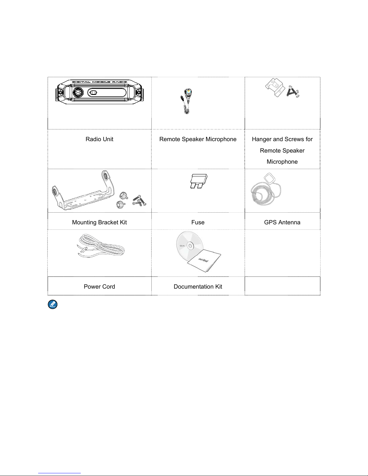
1. Items in the Package .......................................................................................................................... 1
2. Product Overview ............................................................................................................................... 2
2.1 Radio Unit ....................................................................................................................................... 2
2.2 Remote Speaker Microphone ......................................................................................................... 3
3. Installation .......................................................................................................................................... 4
3.1 Instructions ..................................................................................................................................... 4
3.2 Installation Tools ............................................................................................................................. 4
3.3 Installation Procedure ..................................................................................................................... 4
4. Status Indication ................................................................................................................................ 7
4.1 LCD Icon ......................................................................................................................................... 7
4.2 LED Indicator .................................................................................................................................. 7
5. Basic Operations ................................................................................................................................ 9
5.1 Powering On/Off ............................................................................................................................. 9
5.2 Adjusting the Volume ...................................................................................................................... 9
5.3 Selecting a Zone ............................................................................................................................. 9
5.4 Selecting a Channel ........................................................................................................................ 9
5.5 Setting TX Power Level ................................................................................................................ 10
6. Call Services ..................................................................................................................................... 11
6.1 Call on Digital Channel ............................................................................................................ 11
6.2 Call on Analog Channel without Signaling ............................................................................... 13
7. Available Features ............................................................................................................................ 14
8. Troubleshooting ............................................................................................................................... 16
9. Care and Cleaning ............................................................................................................................ 18
10. Optional Accessories ..................................................................................................................... 19

1
1. Items in the Package
Please unpack carefully and check that all items listed below are received. If any item is missing or
damaged, please contact your dealer.
Radio Unit Remote Speaker Microphone Hanger and Screws for
Remote Speaker
Microphone
Mounting Bracket Kit Fuse GPS Antenna
Power Cord Documentation Kit
Note:
The GPS antenna is the standard accessory for the MD65X with GPS feature. The frequency
band is marked on the label of antenna; if not, please refer to the label on the radio for frequency
band information.
Unless otherwise specified, the remote speaker microphone mentioned in this manual refers to
that included in the item list.

2
2. Product Overview
2.1 Radio Unit
Caution:
GPS antenna connector is for MD65X mobile radio with GPS feature only.
Do not block the ventilation hole of the fan.
Clean the fan regularly.
Do not stop the fan with hard objects such as a screwdriver to avoid fan damage.
Do not touch the fan blades when the fan operates to avoid bodily injury.

3
2.2 Remote Speaker Microphone
For enhanced convenience, you may request your dealer to program the TK, P1 and P2 keys as
shortcuts to certain functions. You may refer to Feature Description and Operation Manual for more
details.
Caution: The TK is programmed with emergency feature by default (short press: Emergency On;
long press: Emergency Off). It is programmable by your dealer.

4
3. Installation
3.1 Instructions
Before you install the radio in a vehicle, be sure to read the following instructions carefully:
The radio must work with a 13.6V±15% negative ground electrical system only. And ensure to check
the ground polarity and voltage of the vehicle power supply prior to installation.
Check how long the screws will extend from the bottom surface of the radio before installation. Drill
the mounting hole cautiously to avoid damage to the vehicle wiring and other parts.
Connect the antenna and power cord to the radio, before you install it in the bracket. And make sure
the antenna and power cord are dedicated for digital radios of the Company.
Install the radio with the mounting bracket supplied by the Company, to avoid radio looseness in case
of accidents. The loose radio may cause bodily injury.
Install the radio in a location where it’s easy to reach the front panel controls.
Keep sufficient clearance at the back of the radio for wiring.
Be sure to use the fuse with the same specification for DC power cord upon replacement.
If there are any other device in the vicinity of this radio, the distance between the antenna of this radio
and the antenna of such RF device shall be no less than 10 meters.
3.2 Installation Tools
Drill
Cross head screwdriver
Hex socket sleeve (for 4.8×20mm self-tapping screws assembling)
3.3 Installation Procedure
To install the radio, do as follows:
1. Install the bracket in a location where it’s easy to operate the radio.
2. Connect accessories such as the antenna and power cord to the radio.
3. Slide the radio into the properly mounted bracket and secure it using the locking knobs.
4. Install the remote speaker microphone hanger in a location where it can be reached conveniently.
5. Plug the remote speaker microphone into the radio, but at first align the triangle index on the
remote speaker microphone with the microphone installation index on the microphone connector.
Place the remote speaker microphone on the hanger when you do not use it.
The parts of the radio are illustrated below:

5
No. Part Name No. Part Name
1 Radio Unit 8 Power Interface
2 Locking Knobs 9 Power Cord (black)
3 Mounting Bracket 10 Power Cord (red)
4 4.8×20mm Self-tapping Screws 11 Fuse
5 Remote Speaker Microphone 12 RF Antenna Connector
6 4×16mm Self-tapping Screws 13 GPS Antenna Connector

6
No. Part Name No. Part Name
7 Remote Speaker Microphone Hanger / /

7
4. Status Indication
The LCD display and LED indicators on the remote speaker microphone indicate the operation status of
the radio.
4.1 LCD Icon
Icon Name Icon Radio Status
RSSI Icon More bars indicate better signal strength.
GPS Icon
The GPS feature is enabled, and valid GPS data is
received.
The GPS feature is enabled, but no valid GPS data
is received.
Scan Icon
The radio is scanning.
The radio stays on a non-priority channel.
The radio stays on Priority Channel 1.
The radio stays on Priority Channel 2.
Roam Icon The radio is roaming.
Volume Icon More bars indicate higher volume.
Channel Icon CHXX
Indicates the current channel. “XX” denotes the
channel number, such as “CH01”.
Zone Icon ZONEXX
Indicates the current zone. “XX” denotes the zone
number, such as “ZONE01”.
TX Power Icon
Low TX power for the current channel.
High TX power for the current channel.
4.2 LED Indicator
LED Indication Radio Status
The LED
indicator flashes
Powering on

8
LED Indication Radio Status
green.
The LED
indicator glows
red.
Transmitting
The LED
indicator glows
green.
Receiving
The LED
indicator flashes
orange slowly.
Scanning or roaming
The LED
indicator flashes
orange rapidly.
Emergency
The LED
indicator glows
orange.
Call hung. During a call, you can hold down the PTT key to talk to the other party
before the call hang time expires.

9
5. Basic Operations
5.1 Powering On/Off
Method 1
Method 2
5.2 Adjusting the Volume
Step 1 Press the key on the remote microphone speaker until the icon is shadowed.
Step 2 Press the key to lower the volume and press the key to increase it.
5.3 Selecting a Zone
A zone is a group of channels exhibiting the same property, which is programmed by your dealer and
can facilitate convenient management over the channel. The radio supports 64 zones, each of which
consists of up to 16 channels.
To select a zone, do as follows:
Step 1 Press the key on the remote microphone speaker until ZONEXX (e.g. ZONE01) is
shadowed.
Step 2 Press the / key to select a zone.
5.4 Selecting a Channel
Step 1 Press the key on the remote microphone speaker until CHXX (e.g. CH01) is shadowed.
Step 2 Press the / key to select a channel.
If the Channel Notify feature is enabled by your dealer, the radio will announce the channel number upon

10
channel switching.
5.5 Setting TX Power Level
This feature is to set the TX power level to high or low. High power can extend the signal coverage of the
radio, enabling you to communicate with farther radios. Generally, we recommend you to adopt low
power for battery saving. However, if you cannot communicate with radios located at a distant place with
low power, please select high power.
To set the TX power level, do as follows:
Step 1 Press the key on the remote microphone speaker until the TX power level Icon (e.g. )
is shadowed.
Step 2 Press the / key to switch power level.

11
6. Call Services
After the radio is powered on, you can make and receive calls. To ensure optimal volume of the
receiving radio, keep the palm microphone about 2.5 to 5 centimeters away from your mouth when
transmitting.
6.1 Call on Digital Channel
You can initiate a private call, group call or all call (your radio must be programmed to allow you to use
the all call service) through the same operations on digital channel. You may request the dealer to preset
a regular private call/group call/all call contact for each digital channel.
The differences between private call, group call and all call are that:
In private call and all call, the radio will make a call to the calling party when calling back.
In group call, the radio will make a call to all parties involved when calling back.
Here takes the private call between Radio A and Radio B as example:
Step Operator Operation
1 Radio A Radio A and Radio B select the same digital channel.
2 Radio B Radio A and Radio B select the same digital channel.
3 Radio A Hold down the PTT key on the remote speaker microphone to initiate a call.
Radio A can talk to the microphone when the LED indicator glows red.
The LCD of the remote speaker microphone displays “P + Private Call ID”. Private

12
Step Operator Operation
Call ID is the private ID of Radio B. For example, the private ID of Radio B is 1234,
and then the LCD displays P 1234.
Radio A releases the PTT key to finish talking.
4 Radio B Radio B can receive the call without any operation. When receiving, the LED
indicator glows green.
The LCD of the remote speaker microphone displays “P + Private Call ID”. Private
Call ID is the private ID of Radio A. For example, the private ID of Radio A is 5678,
and then the LCD displays P 5678.
Hold down the PTT key on the remote speaker microphone and talk to the
microphone to respond after Radio A finishes talking. Radio B releases the PTT
key to finish talking.
5 Radio A Radio A can receive the call without any operation. When receiving, the LED
indicator glows green.
The LCD of the remote speaker microphone displays P 1234.
Hold down the PTT key on the remote speaker microphone and talk to the
microphone to respond after Radio B finishes talking. Radio A releases the PTT
key to finish talking.
6 Radio A
and
Radio B
Repeat Step 4 and Step 5 to communicate with each other. If neither party talks
before he duration of LED indicator glowing orange expires, the call will end.
Note
The Call Hang Time (the duration of LED indicator glowing orange) is preset by your dealer.
In private call, group call and all call, the LCD display on the remote speaker microphone is
listed below.
Call Type LCD Display Example
Private Call P + Private Call ID P 1234
Group Call Calling Party:
G + Group Call ID
G 1234

13
Call Type LCD Display Example
Called Party:
G + Group Call ID
P + Private Call ID
G 1234
P 1234
All Call Calling Party:
A + All Call ID
A 1234
Called Party:
A + All Call ID
P + Private Call ID
A 1234
P 1234
6.2 Call on Analog Channel without Signaling
On the analog channel without signaling, the calling operations are the same as that on the digital
channel. The difference is that the called parties are all the users on the channel, rather than the preset
contact for the channel.
Please refer to Feature Description and Operation Manual for operation description on how to make and
receive calls on the analog channel with signaling.

14
7. Available Features
Available features of this radio are listed below. Please refer to Feature Description and Operation
Manual for details.
Feature Type Detailed Feature
Radio Features
Radio setting: Power Level, LED Indicator and Alert Tone
Convenient functionality: Shortcuts, One Touch Call and VOX
Security: Lone Worker
Rent
Audio Optimization
Positioning
Conventional Common
Features
Scan
Talk Around
Digital Features
Access management
Basic voice services: Private Call and Group Call (See Call on Digital
Channel
in this manual)
Auxiliary voice services: All Call (See Call on Digital Channel
in this manual) and Phone
Security
Supplementary services
Patented features
Mobility management
Analog Features
Access management
Voice services (See You can initiate a private call, group call or all call
(your radio must be programmed to allow you to use the all call service)
through the same operations on digital channel. You may request the
dealer to preset a regular private call/group call/all call contact for each
digital channel.
in this manual)

15
Feature Type Detailed Feature
Security
Signaling
Features Developed
with Third Party
API
Accessory Connector

16
8. Troubleshooting
Phenomena Analysis Solution
The radio fails to
power on.
The power cord may be
disconnected.
Properly connect the power cord.
During receiving,
the voice is weak,
discontinuous or
totally inactive.
The volume level may be low.
Increase the volume via the remote speaker
microphone.
The antenna may be loosened
or improperly installed.
Power off the radio and reattach the antenna.
The speaker may be blocked
or damaged.
Clean the surface of the speaker. If the
problem cannot be solved, contact your dealer
or authorized service center for inspection and
repair.
You cannot
communicate with
other members in
analog mode.
The frequency or signaling may
not match that of other
members.
Set your TX/RX frequency and signaling to the
same as that of other members.
You may be too far away from
the group members.
Move towards other members.
In digital mode,
there’s RX
indication on the
radio, but unable to
communicate with
other members.
The digital carrier may be
received but may not be
demodulated due to
inconsistent ID with that of
other members.
Sets the same ID of other members.
Irrelevant
communication or
noise is heard on
the channel.
You may be interrupted by
radios using the same
frequency.
Adjust the squelch level.
The radio may be set with no
signaling.
Set your radio with signaling to avoid
interference at the same frequency, and make
sure that all members share the same
signaling.
Other manuals for MD65X
3
Table of contents
Other Hytera Radio manuals

Hytera
Hytera MD78X User manual

Hytera
Hytera PDC760 User manual

Hytera
Hytera TC-500 User manual

Hytera
Hytera MD65X User manual

Hytera
Hytera PTC760 User manual

Hytera
Hytera PD605 User manual

Hytera
Hytera MD78X User manual

Hytera
Hytera MD652i User manual

Hytera
Hytera HM682 User manual

Hytera
Hytera TM-610 User manual

Hytera
Hytera TM-610 User manual

Hytera
Hytera MD780 User manual

Hytera
Hytera PTC680FXB1 User manual

Hytera
Hytera PD562 User manual

Hytera
Hytera HM652 User manual

Hytera
Hytera MD61 Series User manual

Hytera
Hytera TC-518 OBR User manual

Hytera
Hytera PD66Xi Um Series User manual

Hytera
Hytera HM652GBTV User manual

Hytera
Hytera PDC760UXB2 User manual