6
Contact List
The contact list is used to save private call contact,
group call contact, and all call contact information such
as call alias, call type and call ID.
●Go to the “Menu -> Contact -> Contact List” menu
to access the contact list.
●Press the programmed Contact List key to access
the contact list.
In the “Contact List” menu, you can view, edit or delete
the private contact. You can send to a private call contact
the following commands: Alert Call, Radio Check,
Remote Monitor, Radio Enable or Radio Disable. Please
refer to the Feature Description and Operation Manual
along with the product for details.
Favorite Contact
Favorite Contact is used to save the frequently used
contacts.
●Go to the “Menu -> Contact -> Favorite Contact”
menu to access the favorite contact list.
●Press the programmed Favorite Contact List key
to access the favorite contact list.
In the favorite contact list, you can view, edit or delete the
favorite contacts. You can send to a favorite contact the
following commands: Alert Call, Radio Check, Remote
Monitor, Radio Enable or Radio Disable. Please refer
to the Feature Description and Operation Manual along
with the product for details.
New Contact
New Contact is used to add a new contact to the contact
list.
Go to the “Menu -> Contact -> New Contact” menu to
access the relevant screen. Input the number and alias
of a new contact and save it to the private contact list.
Note:
●The number and alias of a new
contact must be unique.
●You can also save the numbers from
the Call Logs into the contact list.
Call Services
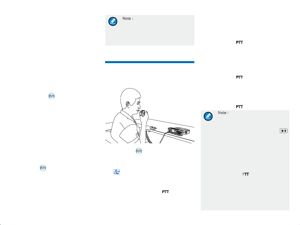
After the radio is powered on, you can make and receive
calls. To ensure optimal volume of the receiving radio,
keep the microphone about 2.5 to 5 centimeters away
from your mouth when transmitting.
2.5~ 5.0CM
Private Call
Initiating a Private Call
When you initiate a private call, the radio will display the
icon . You can make a private call through any of the
following ways:
Preset Contact
In the home screen, hold down the PTT key to initiate a
private call to the private contact preset for the current
channel.
You may request your dealer to preset a regular private
contact for each digital channel.
Contact List
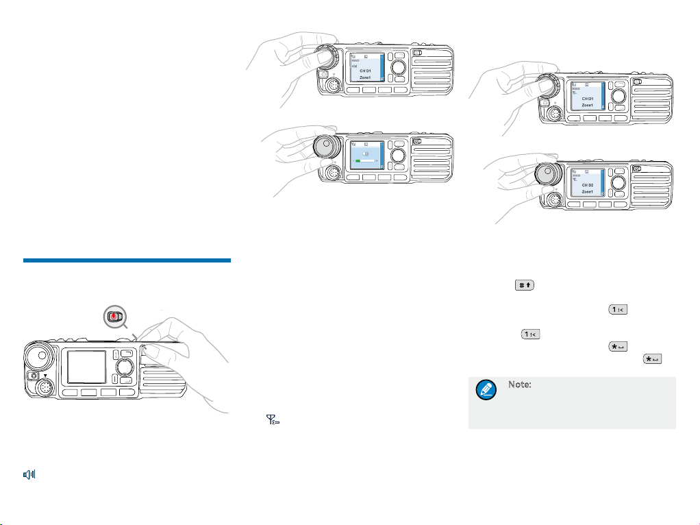
Step 1 Go to “Menu -> Contact -> Contact List”.
Step 2 Use the Up/Down key to select an appropriate
contact.
Step 3 Hold down the PTT key to initiate a private call.
Call Logs
Step 1 Go to “Menu -> Call Logs -> Outgoing/Incoming/
Missed”.
Step 2 Use the Up/Down key to select an appropriate
contact.
Step 3 Hold down the PTT key to initiate a private call.
Manual Dial
Step 1 Go to “Menu -> Contact -> Manual Dial”.
Step 2 Input the private call number using the numeric
keypad.
Step 3 Hold down the PTT key to initiate a private call.
Note:
●If both the Private Call Manual
Dial and Group Call Manual Dial
are available, you can press
to switch between the two dialing
methods, and the radio will display
the call type (Private ID/ Group ID).
●If the Default Numeric Key Selection
feature is enabled by your dealer,
you can enter a private call number
in the home screen, and then hold
down the PTT key to initiate a private
call. However, if the DTMF keypad
is enabled, the number entered in
the home screen is a phone number.
You can dial the private call number
through the “Manual Dial” menu
only.