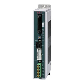
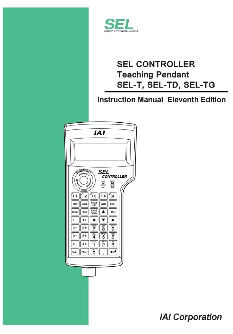
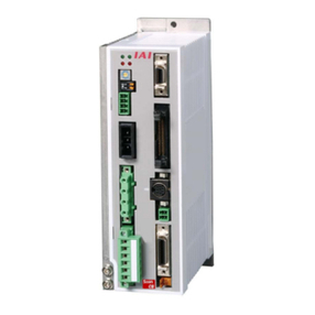
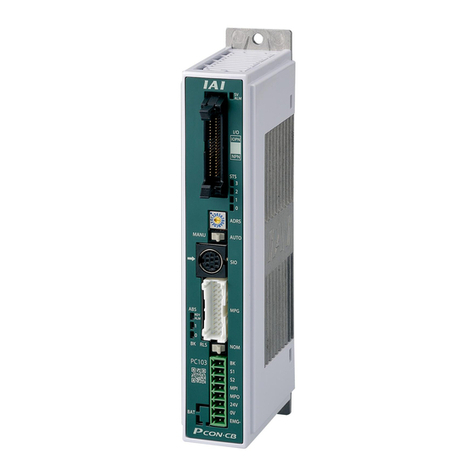
IAI ACON-C User manual

Operation Manual Twelfth Edition
ACON-C/CG
Controller
Positioner Type


Please Read Before Use
Thank you for purchasing our product.
This Operation Manual explains the handling methods, structure and maintenance of this product, among
others, providing the information you need to know to use the product safely.
Before using the product, be sure to read this manual and fully understand the contents explained herein
to ensure safe use of the product.
The CD that comes with the product contains operation manuals for IAI products.
When using the product, refer to the necessary portions of the applicable operation manual by printing
them out or displaying them on a PC.
After reading the Operation Manual, keep it in a convenient place so that whoever is handling this product
can reference it quickly when necessary.
[Important]
xThis Operation Manual is original.
xThe product cannot be operated in any way unless expressly specified in this Operation Manual. IAI
shall assume no responsibility for the outcome of any operation not specified herein.
xInformation contained in this Operation Manual is subject to change without notice for the purpose of
product improvement.
xIf you have any question or comment regarding the content of this manual, please contact the IAI
sales office near you.
xUsing or copying all or part of this Operation Manual without permission is prohibited.
xThe company names, names of products and trademarks of each company shown in the sentences
are registered trademarks.

CAUTION
1. Use Environment
ACON controllers can be used in an environment of pollution degree 2 or equivalent.
2. PC Software and Teaching Pendant Model Numbers
New functions have been added to the entire ACON controller series.
To support these new features, the communication protocol has been changed to the general
Modbus (Modbus-compliant) mode. As a result, the existing PC software programs and teaching
pendants compatible with RCS controllers can no longer be used.
If you are using this controller, use a compatible PC software program and/or teaching pendant
selected from the following model numbers.
Model number Remarks
PC software (with RS232C
communication cable) RCM-101-MW
PC software (with USB
communication cable) RCM-101-USB
Teaching pendant RCM-T, CON-T
Simple teaching pendant RCM-E
Data setting unit RCM-P
All are compatible with existing RCS
controllers.
Touch panel display RCM-PM-01 It is not compatible with RCS
controller.
3. Recommendation for Backing up Latest Data
This product uses nonvolatile memory to store the position table and parameters. Normally the
memory will retain the stored data even after the power is disconnected. However, the data may be
lost if the nonvolatile memory becomes faulty.
(We strongly recommend that the latest position table and parameter data be backed up so that the
data can be restored quickly in the event of power failure, or when the controller must be replaced for
a given reason.)
The data can be backed up using the following methods:
[1] Save to a CD or FD from the PC software.
[2] Hand write the position table and parameter table on paper.

CAUTION
4. Initial Parameter Settings at Startup
After applying power, at least the three parameters specified below must be set in accordance with
the specific application.
Inappropriate settings of these parameters will prevent the controller from operating properly, so
exercise due caution.
For details on how to set the parameters, refer to “Parameter Settings” in the operation manual for
the PC or teaching pendant.
[1] Selecting the PIO pattern
This controller provides six PIO pattern types to meet the needs of various applications.
To select a desired type, set a corresponding value from 0 to 5 in parameter No. 25 (PIO pattern
selection).
The factory setting is “0 [Positioning mode (standard type)]."
Parameter No.
25 setting Feature of PIO pattern
0 Positioning mode (standard type)
A basic type supporting 64 positioning points and two zone outputs.
* How to set zone boundaries within which to output a zone signal:
Zone boundaries are set using parameter Nos. 1 and 2 for one zone output, and in
the position table for another zone output.
1 Teaching mode (Teaching type)
In this type, 64 positioning points and one zone output (boundaries are set in the
position table) are supported.
In addition to the normal positioning mode, the user can also select the teaching
mode in which the actuator can be jogged via commands from a PLC and the
current actuator position can be written to a specified position.
(Note 1) Jog commands from a PLC are also accepted in the positioning mode.
(Note 2) Positions can be rewritten by approximately 100,000 times.
2 256-point mode (256-point type)
The number of positioning points is increased to 256, so only one zone output is
available (boundaries are set in the position table).
3 512-point mode (512-point type)
The number of positioning points is increased to 512, so no zone output is available.
4 Solenoid valve mode 1 (7-point type)
The number of positioning points is limited to seven to offer separate direct
command inputs and position complete outputs for respective positions.
PLC ladder sequence circuits can be designed easily.
5 Solenoid valve mode 2 (3-point type)
Use of the controller as an air cylinder is assumed in this type.
Position complete output signals function differently in this type, compared to the
Solenoid valve mode 1 (7-point type).
Specifically, the signal functions not only to “indicate position complete,” but also to
“detect a position” in the same manner as auto-switches of an air cylinder.

CAUTION
[2] Enabling/disabling the servo ON input signal (SON)
The servo ON input signal has been added to allow for servo ON/OFF control on the PLC side.
Depending on the needs, therefore, the user must enable/disable this signal.
To select a desired setting, set “0” or “1” in parameter No. 21 (Servo ON input disable selection).
Enable (use) 0
Disable (do not use) 1
The factory setting is “0 [Enable].”
[3] Enabling/disabling the pause signal (*STP)
The pause signal uses the contact B logic to provide a failsafe function.
Therefore, this signal must remain ON in normal conditions of use.
Since there are applications where this signal is not used, a parameter is provided to disable the
pause signal so it doesn’t have to be turned ON.
To select a desired setting, set “0” or “1” in parameter No. 15 (Pause input disable selection).
Enable (use) 0
Disable (do not use) 1
The factory setting is “0 [Enable].”

CAUTION
xChanges to Zone Function
Applicable application versions: V0015 and later
Among the zone signal settings, those that result in “Zone setting+ < Zone setting-” are now effective.
V0014 and earlier: “Zone setting+ dZone setting-” oA zone signal is not output.
V0015 and later: “Zone setting+ = Zone setting-” oThis is the only condition in which a zone signal is not
output.
Accordingly, you can now output a zone signal even when a rotary actuator is operated over the 0q
position in the index mode.
An example is given below.
[Rotary actuator in index mode]
Set value Set value
Zone setting+: 70qZone setting+: 315q
Zone setting-: 315qZone setting-: 70q
[Linear axis]
Current position
Zone signal output
Zone signal output
Zone signal ON range
Set value
Zone setting+: 70 mm
Zone setting-: 30 mm
Set value
Zone setting+: 30 mm
Zone setting-: 70 mm

CE Marking
If a compliance with the CE Marking is required, please follow Overseas Standards Compliance Manual
(ME0287) that is provided separately.

Table of Contents
Safety Guide.................................................................................................................... 1
1. Overview ................................................................................................................... 9
1.1 Introduction.................................................................................................................................. 9
1.2 How to Read the Model Number ............................................................................................... 10
1.3 System Configuration ................................................................................................................ 11
1.3.1 Internal Drive-Power Cutoff Relay Type (ACON-C) .............................................. 11
1.3.2 External Drive-Power Cutoff Relay Type (ACON-CG) ..........................................
1.4 Procedure from Unpacking to Test Operation and Adjustment ................................................. 13
1.5 Warranty .................................................................................................................................... 15
2. Specifications .......................................................................................................... 17
2.1 Basic Specifications................................................................................................................... 17
2.2 Name and Function of Each Part of the Controller ................................................................... 18
2.3 External Dimensions.................................................................................................................. 20
3. Installation and Noise Elimination............................................................................ 21
3.1 Installation Environment ............................................................................................................ 21
3.2 Supplied Voltage............................................................................................................................ 21
3.3 Noise Elimination Measures and Grounding............................................................................. 22
3.4 Heat Radiation and Installation.................................................................................................. 23
4. Wiring ...................................................................................................................... 24
4.1 Positioner Type (with Internal Drive-power Cutoff Relay) (ACON-C)........................................ 24
4.1.1 External Connection Diagram............................................................................... 24
4.1.2 Wiring the Power Supply/Emergency-Stop Switch ............................................... 25
4.2 Safety Category Type (External Drive-power Cutoff Relay) (ACON-CG) ................................. 32
4.2.1 External Connection Diagram............................................................................... 32
4.2.2 Wiring the Power Supply/Emergency-Stop Switch ............................................... 33
4.3 Connecting the I/O Cables ........................................................................................................ 36
zPIO pattern 0 [Positioning mode (Standard Type)] .............................................................. 36
zPIO pattern 1 [Teaching mode (Teaching Type)]................................................................. 37
zPIO pattern 2 [256-point mode (256-point type)].................................................................. 38
zPIO pattern 3 [512-point mode (512-point type)].................................................................. 39
zPIO pattern 4 [Solenoid valve mode 1 (7-point Type)]......................................................... 40
zPIO pattern 5 [Solenoid valve mode 2 (3-point Type)]......................................................... 41
1.5.2 Scope of Warranty ................................................................................................ 15
12
1.5.3 Honoring Warranty ................................................................................................ 15
1.5.4 Limited Liability ......................................................................................................15
1.5.5 Conditions of Conformance with Applicable Standards/Regulations, Etc.,
and Applications ....................................................................................................16
1.5.1 Warranty Period ....................................................................................................15
1.5.6 Other Items Excluded from Warranty .................................................................... 16

5.1.1 External Input Specifications................................................................................. 46
5.1.2 External Output Specifications.............................................................................. 47
5.2 PIO Patterns and Signal Assignments ...................................................................................... 48
5.2.1 Explanation of Signal Names................................................................................ 49
zPIO pattern = 0 [Positioning mode (Standard type)] ............................................................ 49
zPIO pattern = 1 [Teaching mode (Teaching type)]............................................................... 50
zPIO pattern = 2 [256-point mode (256-point type)] .............................................................. 51
zPIO pattern = 3 [512-point mode (512-point type)] .............................................................. 52
zPIO pattern = 4 [Solenoid valve mode 1 (7-point type)] ....................................................... 53
zPIO pattern = 5 [Solenoid valve mode 2 (3-point type)] ....................................................... 54
5.2.2 Signal Assignment Table for Respective PIO Patterns ......................................... 55
5.3 Details of I/O Signal Functions ..................................................................................................56
5.3.1. Details of Each Input Signal.................................................................................. 56
Operating mode (RMOD) ..................................................................................................... 56
Start (CSTR)......................................................................................................................... 56
Command position number (PC1 to PC256)........................................................................ 57
Pause (*STP)........................................................................................................................ 57
Home return (HOME) ........................................................................................................... 57
Servo ON (SON)................................................................................................................... 57
Alarm reset (RES) ................................................................................................................ 58
Brake release (BKRL) .......................................................................................................... 58
Operation mode (MODE) ..................................................................................................... 58
Current-position write (PWRT) ............................................................................................. 58
Manual operation switching (JISL) ....................................................................................... 58
Jog (JOG+, JOG-) ................................................................................................................59
Direct position command (ST0 to ST6) [Solenoid valve mode 1 (7-point type)] .................. 59
Movement to each position (ST0 to ST2) [Solenoid valve mode 2 (3-point type)]............... 60
5.3.2 Details of Each Output Signal............................................................................... 61
Operating mode status (RMDS) ........................................................................................... 61
Completed position number (PM1 to PM256) ...................................................................... 61
Moving (MOVE)....................................................................................................................61
Position complete (PEND).................................................................................................... 61
Home return completion (HEND) ......................................................................................... 62
Zone (ZONE1, ZONE2)........................................................................................................ 62
Current operation mode (MODES)....................................................................................... 62
Write completion (WEND) .................................................................................................... 62
Movement complete at each position (PE0 to PE6) [Solenoid valve mode 1 (7-point type)]63
Position detection output at each position (LS0 to LS2) [Solenoid valve mode 2 (3-point
type)]..................................................................................................................................... 63
Ready (SV) ........................................................................................................................... 63
Alarm (*ALM) ........................................................................................................................ 63
Torque level status (TRQS).................................................................................................. 63
Emergency stop (*EMGS) .................................................................................................... 64
Output Signal Changes in Each Mode ................................................................................. 64
4.4 Connecting the Actuator ............................................................................................................ 43
4.4.1 Wiring the ACON-C/CG and Actuator ................................................................... 43
4.5 Connecting the Communication Cable...................................................................................... 45
5. I/O Signal Control and Signal Functions.................................................................. 46
5.1 Interface Circuit ......................................................................................................................... 46

6.2.3 Speed Change during Movement ......................................................................... 72
6.2.4 Operation at Different Acceleration and Deceleration Settings ............................. 72
6.2.5 Pause ................................................................................................................... 73
6.2.6 Zone Signal Output............................................................................................... 73
6.2.7 Home Return ........................................................................................................ 74
6.2.8 Overview of Teaching Mode (Teaching Type) ....................................................... 75
6.2.9 Overview of Solenoid Valve Mode 1 (7-point Type) .............................................. 76
6.2.10 Overview of Solenoid Valve Mode 2 (3-point Type) .............................................. 78
6.3 Power-saving Modes at Standby Positions ............................................................................... 80
7. Operation <Practical Steps>.................................................................................... 82
7.1 How to Start ............................................................................................................................... 82
7.1.1 Timings after Power On ........................................................................................ 82
Procedure after initial startup until actuator adjustment....................................................... 82
Procedure of Normal Operation ........................................................................................... 84
7.1.2 Position Table and Parameter Settings Required for Operation ........................... 87
Startup adjustment ...............................................................................................................87
Safety speed during manual feed......................................................................................... 87
Speed override for movement commands from the PLC ....................................................... 87
Full-scale operation .............................................................................................................. 88
Saving energy when the actuator stands by after completing the home return operation
effected by the HOME input signal .................................................................................... 88
Saving energy when the actuator stands by for a long time at the target position ................. 88
Output mode of complete signal ............................................................................................. 88
7.2 Home Return Operation ............................................................................................................ 89
7.2.1 Method Using the HOME Input Signal (PIO Pattern = 0 to 4) ............................... 89
7.2.2 Method Used When No HOME Input Signal Is Available (PIO Pattern = 5).......... 91
7.3 Positioning Mode (Back and Forth Movement between Two Points)........................................ 92
7.4 Push & Hold Mode..................................................................................................................... 94
7.4.1 Return Action after Push & Hold by Relative Coordinate Specification................. 96
7.5 Speed Change during Movement.............................................................................................. 97
7.6 Operation at Different Acceleration and Deceleration Settings ................................................. 99
7.7 Pause....................................................................................................................................... 101
7.8 Zone Signal Output.................................................................................................................. 103
7.9 Incremental Moves .................................................................................................................. 106
7.9.1 Judgment Method of End Position...................................................................... 108
7.9.2 Notes on Incremental Mode................................................................................ 109
7.10 Jogging/Teaching Using PIO ....................................................................................................112
7.11 Operation of Solenoid Valve Mode 1 (7-point Type).................................................................114
7.12 Operation of Solenoid Valve Mode 2 (3-point Type).................................................................118
6. Data Entry <Basics>................................................................................................ 65
6.1 Description of Position Table ..................................................................................................... 65
6.2 Explanation of Modes ................................................................................................................ 70
6.2.1 Positioning Mode Push = 0................................................................................... 70
6.2.2 Push & Hold Mode Push = Other than 0............................................................... 70

zZone boundary................................................................................................................. 125
zHome return direction ...................................................................................................... 125
zHome return offset ......................................................................................................... 125
8.2.2 Parameters Relating to the Actuator Operating Characteristics.......................... 126
zPIO jog speed ................................................................................................................ 126
zPIO inching distance........................................................................................................ 126
zDefault speed................................................................................................................... 126
zDefault acceleration/deceleration .................................................................................... 126
zDefault positioning band (in-position) .............................................................................. 126
zDefault acceleration/deceleration mode .......................................................................... 126
zCurrent-limiting value during home return ....................................................................... 127
zSpeed override................................................................................................................. 127
zDefault direction of excited-phase signal detection ......................................................... 127
zExcited-phase signal detection time ................................................................................ 127
zPole sensing type............................................................................................................. 127
zSafety speed .................................................................................................................... 127
zAutomatic servo-off delay time ........................................................................................ 128
zDefault standstill mode .................................................................................................... 128
zPush speed ...................................................................................................................... 129
zPush completion judgment time ..................................................................................... 129
zEnable function ................................................................................................................ 130
zPolarity of home check sensor input................................................................................ 130
zHome-sensor input polarity.............................................................................................. 131
zPrimary-filter time constant for position command .......................................................... 131
zS-motion ratio setting....................................................................................................... 131
zBall screw lead length...................................................................................................... 132
zAxis operation type .......................................................................................................... 132
zRotational axis mode selection ........................................................................................ 132
zShortcut selection for rotational axis................................................................................ 132
zAbsolute unit .................................................................................................................... 133
zCurrent-limiting value at stopping due to missed push-motion ...................................... 133
8.2.3 Parameters Relating to the External Interface .................................................... 134
zPIO pattern selection ....................................................................................................... 134
zMovement command type ............................................................................................... 135
zPause input disable selection .......................................................................................... 136
zServo ON input disable selection..................................................................................... 136
zHome-return input disable selection ................................................................................ 136
zOperating-mode input disable selection .......................................................................... 136
zOutput mode of position complete signal ........................................................................ 137
zSIO communication speed............................................................................................... 137
zMinimum delay time for slave transmitter activation........................................................ 137
zSilent interval multiplier .................................................................................................... 138
8.2.4 Servo Gain Adjustment ....................................................................................... 139
zServo gain number........................................................................................................... 139
zSpeed loop proportional gain........................................................................................... 139
zTorque filter time constant ............................................................................................... 140
zCurrent control range number.......................................................................................... 140
zFeed-forward gain............................................................................................................ 140
8. Parameters............................................................................................................ 122
8.1 Parameter Table ...................................................................................................................... 122
8.2 Detail Explanation of Parameters............................................................................................ 124
8.2.1 Parameters Relating to the Actuator Stroke Range ............................................ 124
zSoft limit ........................................................................................................................... 124
zSoftware limit margin ....................................................................................................... 124

9.5 Detail Connection Diagram...................................................................................................... 145
10. Troubleshooting..................................................................................................... 147
10.1 Action to Be Taken upon Occurrence of Problem ................................................................... 147
10.2 Alarm Level Classification ....................................................................................................... 148
10.3 Alarm Description Output Using PIO....................................................................................... 149
10.4 Alarm Description and Cause/Action....................................................................................... 150
(1) Message level alarms......................................................................................................... 150
(2) Cold-start level alarms........................................................................................................ 153
10.5 Messages Displayed during Operation Using the Teaching Pendant ..................................... 156
10.6 Specific Problems .................................................................................................................... 159
zI/O signals cannot be exchanged with the PLC. ................................................................ 159
zThe ALM lamp illuminates when the power is input........................................................... 159
zThe SV lamp does not illuminate when the servo ON signal is input after the power was
input.................................................................................................................................... 159
zHome return ends in the middle in a vertical application. .................................................. 160
zThe actuator overshoots when decelerated to a stop. ....................................................... 160
zThe home and target positions sometimes shift................................................................. 160
zThe actuator moves only a half of, or twice as much as, the specified movement............ 160
zThe SV lamp blinks. ........................................................................................................... 160
* Appendix ................................................................................................................... 161
List of Specifications of Connectable Actuators................................................................................. 161
Positioning Sequence ........................................................................................................................ 174
Recording of Parameters................................................................................................................... 177
Change History.................................................................................................................................. 179
9. PC/Teaching Pendant Connection Method in Multi-axis Configurations................ 141
9.1 Connection Example ............................................................................................................... 141
9.2 Name and Function of Each Part of the SIO Converter .......................................................... 142
9.3 Address Switch........................................................................................................................ 144
9.4 Connection Cables .................................................................................................................. 144


1
Safety Guide
When designing and manufacturing a robot system, ensure safety by following the safety
precautions provided below and taking the necessary measures.
Regulations and Standards Governing Industrial Robots
Safety measures on mechanical devices are generally classified into four categories under the
International Industrial Standard ISO/DIS 12100, “Safety of machinery,” as follows:
Safety measures Inherent safety design
Protective guards --- Safety fence, etc.
Additional safety measures --- Emergency stop device, etc.
Information on use --- Danger sign, warnings, operation manual
Based on this classification, various standards are established in a hierarchical manner under the
International Standards ISO/IEC. The safety standards that apply to industrial robots are as follows:
Type C standards (individual safety standards) ISO10218 (Manipulating industrial robots – Safety)
JIS B 8433
(Manipulating industrial robots – Safety)
Also, Japanese laws regulate the safety of industrial robots, as follows:
Industrial Safety and Health Law Article 59
Workers engaged in dangerous or harmful operations must receive special education.
Ordinance on Industrial Safety and Health
Article 36 --- Operations requiring special education
No. 31 (Teaching, etc.) --- Teaching and other similar work involving industrial robots
(exceptions apply)
No. 32 (Inspection, etc.) --- Inspection, repair, adjustment and similar work involving industrial
robots (exceptions apply)
Article 150 --- Measures to be taken by the user of an industrial robot

2
Requirements for Industrial Robots under Ordinance on Industrial
Safety and Health
Work area Work condition Cutoff of drive
source Measure Article
Signs for starting operation Article 104
Outside
movement
range
During
automatic
operation
Not cut off Installation of railings,
enclosures, etc. Article 150-4
Cut off (including
stopping of
operation)
Sign, etc., indicating that work is
in progress Article 150-3
Preparation of work rules Article 150-3
Measures to enable immediate
stopping of operation Article 150-3
Sign, etc., indicating that work is
in progress Article 150-3
Provision of special education Article 36-31
During
teaching, etc.
Not cut off
Checkup, etc., before
commencement of work Article 151
To be performed after stopping
the operation Article 150-5
Cut off
Sign, etc., indicating that work is
in progress Article 150-5
Preparation of work rules Article 150-5
Measures to enable immediate
stopping of operation Article 150-5
Sign, etc., indicating that work is
in progress Article 150-5
Inside
movement
range
During
inspection, etc. Not cut off (when
inspection, etc.,
must be performed
during operation)
Provision of special education
(excluding cleaning and
lubrication)
Article 36-32

3
Applicable Models of IAI’s Industrial Robots
Machines meeting the following conditions are not classified as industrial robots according to Notice of
Ministry of Labor No. 51 and Notice of Ministry of Labor/Labor Standards Office Director (Ki-Hatsu No.
340):
(1) Single-axis robot with a motor wattage of 80 W or less
(2) Combined multi-axis robot whose X, Y and Z-axes are 300 mm or shorter and whose rotating
part, if any, has the maximum movement range of within 300 mm3including the end of the
rotating part
(3) Multi-joint robot whose movable radius and Z-axis are within 300 mm
Among the products featured in our catalogs, the following models are classified as industrial robots:
1. Single-axis ROBO Cylinders
RCS2/RCS2CR-SS8whose stroke exceeds 300 mm
2. Single-axis robots
The following models whose stroke exceeds 300 mm and whose motor capacity also exceeds 80 W:
ISA/ISPA, ISDA/ISPDA, ISWA/ISPWA, IF, FS, NS
3. Linear servo actuators
All models whose stroke exceeds 300 mm
4. Cartesian robots
Any robot that uses at least one axis corresponding to one of the models specified in Sections 1 to 3
and also CT4
5. IX SCARA robots
All models whose arm length exceeds 300 mm
(All models excluding IX-NNN1205/1505/1805/2515, NNW2515 and NNC1205/1505/1805/2515)

4
Notes on Safety of Our Products
Common items you should note when performing each task on any IAI robot are explained below.
No. Task Note
1 Model
selection
zThis product is not planned or designed for uses requiring high degrees of safety.
Accordingly, it cannot be used to sustain or support life and must not be used in
the following applications:
[1] Medical devices relating to maintenance, management, etc., of life or health
[2] Mechanisms or mechanical devices (vehicles, railway facilities, aircraft
facilities, etc.) intended to move or transport people
[3] Important safety parts in mechanical devices (safety devices, etc.)
zDo not use this product in the following environments:
[1] Place subject to flammable gases, ignitable objects, flammables, explosives,
etc.
[2] Place that may be exposed to radiation
[3] Place where the surrounding air temperature or relative humidity exceeds the
specified range
[4] Place subject to direct sunlight or radiated heat from large heat sources
[5] Place subject to sudden temperature shift and condensation
[6] Place subject to corrosive gases (sulfuric acid, hydrochloric acid, etc.)
[7] Place subject to excessive dust, salt or iron powder
[8] Place where the product receives direct vibration or impact
zDo not use this product outside the specified ranges. Doing so may significantly
shorten the life of the product or result in product failure or facility stoppage.
2 Transportation zWhen transporting the product, exercise due caution not to bump or drop the
product.
zUse appropriate means for transportation.
zDo not step on the package.
zDo not place on the package any heavy article that may deform the package.
zWhen using a crane with a capacity of 1 ton or more, the crane must be operated
by personnel qualified to operate cranes and perform slinging operations.
zWhen using a crane or other equipment, never use it to hoist any article exceeding
the rated load of the applicable crane, etc.
zUse hoisting accessories suitable for the article to be hoisted. Select appropriate
hoisting accessories by making sure there is an ample allowance for safety in their
cutting load, etc.
zDo not climb onto the article being hoisted.
zDo not keep the article hoisted.
zDo not stand under the hoisted article.
3Storage,
preservation
zThe storage, preservation environment should conform to the installation
environment. Among others, be careful not to cause condensation.

5
No. Task Note
(1) Installing the robot, controller, etc.
zBe sure to firmly secure and affix the product (including its work part).
If the product tips over, drops, malfunctions, etc., damage or injury may result.
zDo not step on the product or place any article on top. The product may tips over
or the article may drop, resulting in injury, product damage, loss of/drop in product
performance, shorter life, etc.
zIf the product is used in any of the following places, provide sufficient shielding
measures:
[1] Place subject to electrical noise
[2] Place subject to a strong electric or magnetic field
[3] Place where power lines or drive lines are wired nearby
[4] Place subject to splashed water, oil or chemicals
(2) Wiring the cables
zUse IAI’s genuine cables to connect the actuator and controller or connect a
teaching tool, etc.
zDo not damage, forcibly bend, pull, loop round an object or pinch the cables or
place heavy articles on top. Current leak or poor electrical continuity may occur,
resulting in fire, electric shock or malfunction.
zWire the product correctly after turning off the power.
zWhen wiring a DC power supply (+24 V), pay attention to the positive and negative
polarities.
Connecting the wires in wrong polarities may result in fire, product failure or
malfunction.
zBe sure to connect the cable connectors without fail and firmly. Failing to do so
may result in fire, electric shock or product malfunction.
zDo not cut and reconnect the cables of the product to extend or shorten the
cables. Doing so may result in fire or product malfunction.
(3) Grounding
zBe sure to provide class D (former class 3) grounding for the controller. Grounding
is required to prevent electric shock and electrostatic charges, improve noise
resistance and suppress unnecessary electromagnetic radiation.
4 Installation/
startup
(4) Safety measures
zImplement safety measures (such as installing safety fences, etc.) to prevent entry
into the movement range of the robot when the product is moving or can be
moved. Contacting the moving robot may result in death or serious injury.
zBe sure to provide an emergency stop circuit so that the product can be stopped
immediately in case of emergency during operation.

6
No. Task Note
4 Installation/
startup
zImplement safety measures so that the product cannot be started only by turning
on the power. If the product starts suddenly, injury or product damage may result.
zImplement safety measures so that the product will not start upon cancellation of
an emergency stop or recovery of power following a power outage. Failure to do
so may result in injury, equipment damage, etc.
zPut up a sign saying “WORK IN PROGRESS. DO NOT TURN ON POWER,” etc.,
during installation, adjustment, etc. If the power is accidently turned on, electric
shock or injury may result.
zImplement measures to prevent the work part, etc., from dropping due to a power
outage or emergency stop.
zEnsure safety by wearing protective gloves, protective goggles and/or safety
shoes, as necessary.
zDo not insert fingers and objects into openings in the product. Doing so may result
in injury, electric shock, product damage, fire, etc.
zWhen releasing the brake of a vertically installed actuator, be careful not to pinch
your hand or damage the work part, etc., due to the slider dropping by its dead
weight.
5 Teaching zWhenever possible, perform teaching from outside the safety fences. If teaching
must be performed inside the safety fences, prepare “work rules” and make sure
the operator understands the procedures thoroughly.
zWhen working inside the safety fences, the operator should carry a handy
emergency stop switch so that the operation can be stopped any time when an
abnormality occurs.
zWhen working inside the safety fences, appoint a safety watcher in addition to the
operator so that the operation can be stopped any time when an abnormality
occurs. The safety watcher must also make sure the switches are not operated
inadvertently by a third party.
zPut up a sign saying “WORK IN PROGRESS” in a conspicuous location.
zWhen releasing the brake of a vertically installed actuator, be careful not to pinch
your hand or damage the work part, etc., due to the slider dropping by its dead
weight.
* Safety fences --- Indicate the movement range if safety fences are not provided.
6 Confirmation
operation
zAfter teaching or programming, carry out step-by-step confirmation operation
before switching to automatic operation.
zWhen carrying out confirmation operation inside the safety fences, follow the
specified work procedure just like during teaching.
zWhen confirming the program operation, use the safety speed. Failure to do so
may result in an unexpected movement due to programming errors, etc., causing
injury.
zDo not touch the terminal blocks and various setting switches while the power is
supplied. Touching these parts may result in electric shock or malfunction.
Other manuals for ACON-C
2
This manual suits for next models
1
Table of contents
Other IAI Controllers manuals