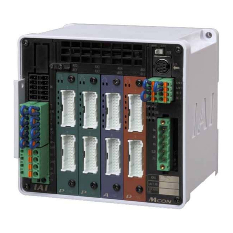
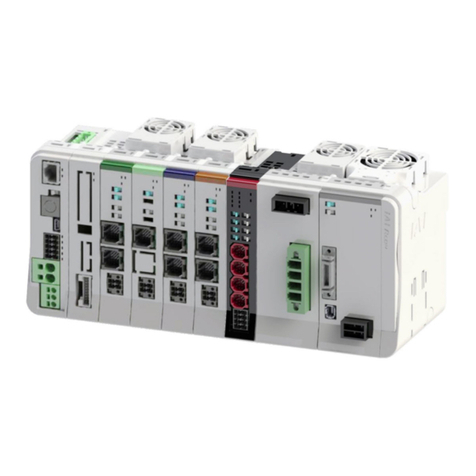
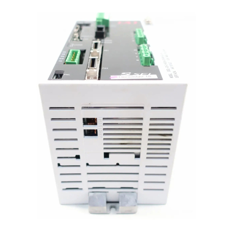
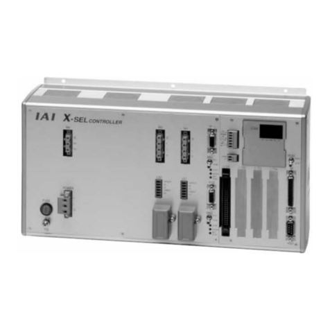
IAI XSEL-R User manual

XSEL-R/S, RX/SX, RXD/SXD
First Step Guide
First Edition
Thank you for purchasing our product.
Make sure to read the Safety Guide and detailed Instruction Manual (CD/DVD) included with the product in addition to
this First Step Guide to ensure correct use.
This Instruction Manual is original.
•Using or copying all or part of this Instruction Manual without permission is prohibited.
•The company names, names of products and trademarks of each company shown in the sentences are registered
trademarks.
Product Check
This product is comprised of the following parts if it is of standard configuration:
If you find any fault in the contained model or any missing parts, contact us or our distributor.
1. Parts (Options are excluded.)
Quantity
No. Part Name Remarks
R/RX/RXD S/SX/SXD
1 Controller Refer to “How to read the model plate” and
“How to read the model of the controller.”
Accessories
2 System I/O plug MC1.5/9-ST-3.5 (Maker: PHOENIX CONTACT) 2 2
3 AC Power Supply plug
GMSTB2.5/6-STF-7.62 (Maker: PHOENIX CONTACT)
1 1
4 Brake Power Input Plug MC1.5/2-ST-3.5 (Maker: PHOENIX CONTACT) 1 1
5 Dummy plug DP-2 - 1
6 For DeviceNet Type
SMSTB2.5/5-STF-5.08AU (Maker: PHOENIX CONTACT)
1 1
7 For CC-Link Type
MSTB2.5/5-ST-5.08AU (Maker: PHOENIX CONTACT)
1 1
8 First Step Guide 1 1
9 Operation Manual
(CD/DVD) 1 1
10 Safety Guide 1 1
2. Teaching Tool (Optional accessory)
The personal computer application software or teaching pendant is required for the operations
including program creation and setup such as position setting and parameter setting with teaching.
Any of teaching tools needs to be prepared.
Applicable
Controller
No. Part Name Model
R/RX/RXD S/SX/SXD
1 PC Software (with RS232C Cable + Emergency Stop Box) IA-101-X-MW {×
2 PC Software (with USB Conversion Adapter + RS232C Cable +
Emergency Stop Box)
IA-101-X-USBMW
{×
3 PC Software
(Safety Categories 4 compliance cable + Emergency Stop Box)
IA-101-XA-MW {{
4 Teaching pendant SEL-T {{
5 Teaching pendant (with deadman switch) SEL-TD {{
6 Teaching pendant
(with deadman switch + TP adapter (IA-LB-TG))
SEL-TG {{
7 Teaching pendant IA-T-X {×
8 Teaching pendant (with deadman switch) IA-T-XD {×
3. Operation manuals related to this product, which are contained in the operation manual
(CD/DVD).
No. Name Manual No.
1 SEL language programming manual ME0224
2 XSEL Controller P/Q/PX/QX/PCT/QCT/R/S/RX/SX/RXD/SXD
RC Gateway Function Operation Manual ME0188
3 PC Software IA-101-X-MW/IA-101-X-USBMW Operation Manual ME0154
4 Teaching pendant SEL-T/TD/TG Operation Manual ME0183
5 Teaching pendant IA-T-X/XD Operation Manual ME0160
6 DeviceNet Operation Manual ME0124
7 CC-Link Operation Manual ME0123
8 PROFIBUS-DP Operation Manual ME0153
9 Ethernet Operation Manual ME0140
10 EtherCAT Operation Manual ME0309
11 EtherNet/IP Operation Manual ME0308
12 IA Net Operation Manual ME0307
4. How to read the model plate
5. How to read the model
5.1 Multi-Axis Type Controller
*1 In this type, the safety circuit can be configured with the motor driving power source separated.
Note 1 Any of the RCS2-R**7 series, RCS-RB75 series unit, RCS-G20, RCS-R* or the linear motor actuator
(LSA) is not connected.
5.2 SCARA Robot + Additional Axes (4 axes Max.) Type Controller
*1 In this type, the safety circuit can be configured with the motor driving power source separated.
Note 1 Any of the RCS2-R**7 series, RCS-RB75 series unit, RCS-G20, RCS-R* or the linear motor actuator
(LSA) is not connected.
[Restrictions on Connected Axes to XSEL-RX/SX]
Total Wattage and Number of Connectable Axes
SCARA Model Single-phase type 3-phase type
IX-NNN1205/1505/1805 1500W in total or less
(4 axes at maximum)
750W max. for 1 axis
1500W in total or less
(4 axes at maximum)
750W max. for 1 axis
IX-N2515H/3015H/3515H 1500W in total or less
(4 axes at maximum)
750W max. for 1 axis
IX-N5020H/6020H 600W in total or less
(4 axes at maximum)
600W max. for 1 axis
IX-N70H/80H unavailable
IX-NSN5016H/6016H unavailable
5.3 SCARA Robot 2-Unit Connection Dedicated Controller
*1 In this type, the safety circuit can be configured with the motor driving power source separated.
[Limitations in SCARA Robot Combination in XSEL-RXD/SXD]
(1) 3-phase type
First Unit Second Unit
IX-NNN1205/1505/1805
IX-N2515H/3015H/3515H
IX-NNN1205/1505/1805
IX-N2515H/3015H/3515H
IX-N5020H/6020H IX-NNN1205/1505/1805
Basic Specifications
Specifications
Specification Item XSEL-R/RX/RXD XSEL-S/SX/SXD
Number of controlled axes
XSEL-R/S : 1-axis to 8-axis
XSEL-RX/SX : SCARA Robot 1-axis to 4-axis, Additional 5-axis to 8-axis
XSEL-RXD/SXD : SCARA Robot 1-axis to 4-axis , 5-axis to 8-axis
Applicable motor capacity 20W to 750W
Total connectable wattage 3-phase type controller: 2400W
Single-phase type controller: 1600W (Only for R/S)
Abnormal control supply voltage Single-phase AC200V to 230V±10%
Motor Driving Source Voltage 3-phase AC200V to 230V±10% / Single-phase AC200V to 230V±10%
Power Supply Frequency 50Hz/60Hz
Control power supply 60A
Less than 1200W
60A (MAX.)
Rush Current
(Note 1)
Motor
drive
power
supply
1200W or more
120A (MAX.)
Control power supply 0.4mA 0.2mALeakage
Current
(Note 2)
(Excluding Higher
Harmonic Content)
Motor drive power
supply 2mA or less
Heat Generation [Refer to the Item for the Power Capacity and Heating Value]
PIO Power Supply
(Note 3)
DC24V±10% (Supplied from external equipment)
Electromagnetic Brake Power Supply
(For the actuator with the brake)
DC24V±10% Per 1 actuator Approx. 0.35A
(Supplied from external equipment)
Transient Power Cutoff Durability 10ms (when power source frequency 50Hz is used),
8ms (when power source frequency 60Hz is used)
Motor Control System AC Full - digital Servo
Applicable Encoder Incremental Serial Encoder or Absolute Serial Encoder
Speed Setting From 1mm/s The upper limit depends on the specifications of actuator
Acceleration Setting From 0.01G The upper limit depends on the specifications of actuator
XSEL
-
R
-
8
-
400A
-
200A
-
100AB
-
60A
-
400A
-
200A
-
100AB
-
60A
-
EPEIA
-
DGN1
-
2
-
3
X Y Z [
(Axis 1)
[
(Axis 2)
[
(Axis 3)
[
(Axis 4)
[
(Axis 5)
[
(Axis 6)
[
(Axis 7)
[
(Axis 8)
\]^_
Model table
[
Details of axis 1 to axis 8
(Note 1),
\
Network Slot
]
I/O slots
X
Series
Y
Controller
type
Z
Numbe
r
of axes
Motor
Wattage
Encode
r
type Brake Creep
Home
Sensor
(LS)
Synchro-
nization
Desig-
nation
Slot 1 Slot 2 Slot 3 Slot 1 Slot 2
^
I/O Flat
cable
length
_
Power
supply
voltage
E
(
Not for use
)
E
(
Not for use
)
N1
Extension PIO
Input32/Output16
NPN Board
N1
Extension PIO
Input32/Output16
NPN Board
N2
Extension PIO
Input16/Output32
NPN Board
N2
Extension PIO
Input16/Output32
NPN Board
N3
Extension PIO
Input48/Output48
NPN Board
N3
Extension PIO
Input48/Output48
NPN Board
P1
Extension PIO
Input32/Output16
PNP Board
P1
Extension PIO
Input32/Output16
PNP Board
P2
Extension PIO
Input16/Output32
PNP Board
P2
Extension PIO
Input16/Output32
PNP Board
P3
Extension PIO
Input48/Output48
PNP Board
P3
Extension PIO
Input48/Output48
PNP Board
MC
Electronic Cam
Pulse I/O
Board
MC
Electronic Cam
Pulse I/O
Board
XSEL
R
(Standard
Type)
S
*1
(Global
Type)
1
(1
-axis
)
2
(2
-axis
)
3
(3
-axis
)
4
(4
-axis
)
5
(5
-axis
)
6
(6
-axis
)
7
(7
-axis
)
8
(8
-axis
)
12
(12W)
20
(20W)
30D
(30W for DS)
30R
(30W for RS)
60
(60W)
100
(100W)
100S
(100Wfor Linear)
150
(150W)
200
(200W)
200S
(200W for Linear)
300
(300W)
400
(400W)
600
(600W)
750
(750W)
I
(Incre-
mental)
A
(Abso-
lute)
G
(Spurious
Absolute)
Not
Specified
(w/o Brake)
B
(w/ Brake)
Not
Specified
(w/o Creep)
C
(w/ Creep)
Not
Specified
(w/o
Home
Sensor
)
L
(w/
Home
Sensor
)
Not
Specified
(No
Synchroni-
zation)
M
(Master-
Axis
Designation)
S
(Slave-
Axis
Designation)
E
Not for use
EP
EtherNet/IP
Communic-
ation Board
EC
EtherCAT
Communic-
ation Board
E
Not for use
DV
DeviceNet
Input256/
Output256
CC
CC-Link
Input256/
Output256
PR
PROFIBUS
Input256/
Output256
E
IA Net
not
Corresp-
onding
IA
IA Net
Corresp-
onding
DG
DV Gateway
Master Board
2 : 2m
(Standard)
3 : 3m
5 : 5m
0:None
(*1)
2: Single-
phase 200V
2L: Only for
Linear
Single-
phase 200V
3: 3-phase
200V
3L: Only for
Linear
3-phase 200V
XSEL
-
RX8
-
NNN5020H
-
400A
-
200A
-
100AB
-
60A
-
EPEIA
-
DGN1
-
2
-
3
X YZ[
(Axis 5)
[
(Axis 6)
[
(Axis 7)
[
(Axis 8)
\]^_
Model table
[
Details of axis 5 to axis 8
(Note 1)
\
Network Slot
]
I/O slots
X
Series
Y
Controller
type
Z
SCARA
Robot Model
Motor
Wattage
Encoder
type Brake Creep
Home
Sensor
(LS)
Synchro-
nization
Desig-
nation
Slot 1 Slot 2 Slot
3
Slot 1 Slot 2
^
I/O Flat
cable
length
_
Power
supply
voltage
E
(
Not for use
)
E
(
Not for use
)
N1
Extension PIO
Input32/Output16
NPN Board
N1
Extension PIO
Input32/Output16
NPN Board
N2
Extension PIO
Input16/Output32
NPN Board
N2
Extension PIO
Input16/Output32
NPN Board
N3
Extension PIO
Input48/Output48
NPN Board
N3
Extension PIO
Input48/Output48
NPN Board
P1
Extension PIO
Input32/Output16
PNP Board
P1
Extension PIO
Input32/Output16
PNP Board
P2
Extension PIO
Input16/Output32
PNP Board
P2
Extension PIO
Input16/Output32
PNP Board
P3
Extension PIO
Input48/Output48
PNP Board
P3
Extension PIO
Input48/Output48
PNP Board
XSEL
RX4
(1unit of SCARA)
RX5
(1unit of
SCARA+Single
Axis 1Axis)
RX6
(1unit of
SCARA+Single
Axis 2Axis)
RX7
(1unit of
SCARA+Single
Axis 3Axis)
RX8
(1unit of
SCARA+Single
Axis 4Axis)
SX4
*1
(1unit of SCARA)
SX5
*1
(1unit of
SCARA+Single
A
xis 1Axis Safety
Category Type)
SX6
*1
(1unit of
SCARA+Single
Axis 2xis Safety
Category Type)
SX7
*1
(1unit of
SCARA+Single
Axis 3
A
xis Safety
Category Type)
SX8
*1
(1unit of
SCARA+Single
Axis 4
A
xis Safety
Category Type)
NNN1205 to
8040H
NSN5016H to
6016H
(High-Speed
Type)
NNC1205 to
8040H
(Clean Type)
NNW2515H to
8040H
(Splash Proof
Type)
TNN3015H to
3515H
(Wall-Mount
Type)
UNN3015H to
3515H
(Wall-Mount
Inverse Type)
HNN5020H to
8040H
(Ceiling-Mount
Type)
INN5020H to
8040H
(Inverse type)
12
(12W)
20
(20W)
30D
(30W for
DS)
30R
(30W for
RS)
60
(60W)
100
(100W)
100S
(100W for
Linear)
150
(150W)
200
(200W)
200S
(200W for
Linear)
300
(300W)
400
(400W)
600
(600W)
750
(750W)
I
(Incre-
mental)
A
(Abso-
lute)
G
(Spurious
Absolute
)
Not
Specified
(w/o
Brake
)
B
(w/
Brake)
Not
Specified
(w/o
Creep)
C
(w/
Creep)
Not
Specified
(w/o
Home
Sensor
)
L
(w/
Home
Sensor
)
Not
Specified
(No
Synchroni-
zation)
M
(Master-
Axis
Designation
)
S
(
Slave-
Axis
Designation
)
E
Not for use
EP
EtherNet/IP
Communi-
cation Board
EC
EtherCAT
Communi-
cation Board
E
Not for use
DV
DeviceNet
Input256/
Output256
CC
CC-Link
Input256/
Output256
PR
PROFIBUS
Input256/
Output256
E
IA Net
not
Corres-
ponding
IA
IA Net
Corres-
ponding
DG
DV Gateway
Master Board
2 : 2m
(
Standard
)
3 : 3m
5 : 5m
0:None
(*1)
3:
3-phase
200V
XSEL
-
RX
D
8
-
NNN5020H
-
NNN5020H
-
EPEIA
-
DGN1
-
2
-
3
X Y Z [ \ ] ^ _
Model table
\
Network Slot
]
I/O slots
X
Series
Y
Controller
type
Z
SCARA Robot
Model
1
[
SCARA Robot
Model 2
Slot 1 Slot 2 Slot
3
Slot 1 Slot 2
^
I/O Flat
cable
length
_
Power
supply
voltage
E
(
Not for use
)
E
(
Not for use
)
N1
Extension PIO
Input32/Output16
NPN Board
N1
Extension PIO
Input32/Output16
NPN Board
N2
Extension PIO
Input16/Output32
NPN Board
N2
Extension PIO
Input16/Output32
NPN Board
N3
Extension PIO
Input48/Output48
NPN Board
N3
Extension PIO
Input48/Output48
NPN Board
P1
Extension PIO
Input32/Output16
PNP Board
P1
Extension PIO
Input32/Output16
PNP Board
P2
Extension PIO
Input16/Output32
PNP Board
P2
Extension PIO
Input16/Output32
PNP Board
P3
Extension PIO
Input48/Output48
PNP Board
P3
Extension PIO
Input48/Output48
PNP Board
XSEL
RXD8
(For connection
of 2 units of
SCARA)
SXD8
*1
(For connection
of 2 units of
SCARA
Safety Category
Type)
NNN1205 to 1805
NNN2515H to 6030H
(Standard Type)
NNC1205 to 1805
NNC2515H to 6030H
(Clean Type)
NNW2515H to 6030H
(Splash Proof Type)
TNN3015H to 3515H
(Wall-Mount Type)
UNN3015H to 3515H
(Wall-Mount Inverse
Type)
HNN5020H to 6020H
(Ceiling-Mount Type)
INN5020H to 6020H
(Inverse type)
NNN1205 to 1805
NNN2515H to 6030H
(Standard Type)
NNC1205 to 1805
NNC2515H to 6030H
(Clean Type)
NNW2515H to 6030H
(Splash Proof Type)
TNN3015H to 3515H
(Wall-Mount Type)
UNN3015H to 3515H
(Wall-Mount Inverse
Type)
HNN5020H to 6020H
(Ceiling-Mount Type)
INN5020H to 6020H
(Inverse type)
E
Not for
use
EP
EtherNet/IP
Communi-
cation
Board
EC
EtherCAT
Communi-
cation
Board
E
Not for use
DV
DeviceNet
Input256/
Output256
CC
CC-Link
Input256/
Output256
PR
PROFIBUS
Input256/
Output256
E
IA Net
not
Corres-
ponding
IA
IA Net
Corres-
ponding
DG
DV Gateway
Master Board
2 : 2m
(Standard)
3 : 3m
5 : 5m
0:None
(*1)
3: 3-phase
200V
MODEL XSEL-R-8-400A-200A-100AB-60A-400A-200A-100AB-60A-EPEIA-DGN1-2-3
SERIALNo.200198765 MADEINJAPAN
Model
Serial number
Field Network Type
(DeviceNet, CC-Link, PROFIBUS-DP, EtherCAT,
EtherNet/IP)
Warning : Operation of this equipment requires detailed installation and operation instructions which are
provided on the CD/DVD Manual included in the box this device was packaged in. It should be
retained with this device at all times.
A hard copy of Manual can be requested by contacting your nearest IAI Sales Office listed at
the back cove
r
of the Instruction Manual or on the First Ste
p
Guide.

Specification Item XSEL-R/RX/RXD XSEL-S/SX/SXD
Teaching port RS232C: 1CH (X-SEL Serial Communication protocol (Format B))
Baud rate : MAX. 115.2kbps Connector: D-sub 25 pin
Port 1
RS232C: 1CH (X-SEL Serial Communication protocol (Format B))
Baud rate: MAX. 115.2kbps Connector: D-sub 9 pin
Control available with serial communication (Cable length Max.10m)
[General-purpose RS232C]
RS232C: 1CH (X-SEL Serial Communication protocol (Format B))
Baud rate: MAX. 115.2kbps Connector: D-sub 9 pin
Control available with serial communication (Cable length Max.10m)
Serial
Communication
Interface
Port 2 [RC Gateway]
RS485: 1CH (Modbus protocol RTU/ASCII conformance)
Baud rate: MAX. 230.4kbps Connector: D-sub 9 pin
Control available with serial communication (Cable length Max.100m)
PIO Type
PIO Board MAX. 2 pieces
Signal I/O dedicated for 24V DC (Input and output ports, selected from
NPN/PNP) [Refer to 5. How to read controller model code]
External
Interface
Field Network Type
DeviceNet, CC-Link, PROFIBUS, EtherNet/IP, EtherCAT
(For either of DeviceNet, CC-Link or PROFIBUS and either of EtherNet/IP or
EtherCAT, the boards can be inserted at the same time.)
[Refer to each Fieldbus Instruction Manual]
Expanded I/O Unit (option) PIO Board MAX. 4 pieces
Data Setting and Input PC software or teaching pendant
Program Specification Super SEL language
Max. Number of Program Steps 9999 Step
Max. Number of Positions
1-Axis Type: 53332 positions, 5-Axis Type: 22856 positions
2-Axis Type: 40000 positions, 6-Axis Type: 20000 positions
3-Axis Type: 32000 positions, 7-Axis Type: 17776 positions
4-Axis Type: 26666 positions, 8-Axis Type: 16000 positions
Max. Number of Programs 128 programs
Max. Number of Multitask Programs 16 programs
Data Retention Memory Flash ROM + FRAM
Clock Function
Retaining time after power turned OFF: approximately 10 days
Time for battery charge after power is ON after the clock data is lost:
approximately 100 hours
Panel Unit PU-1 (option) Controller status display
System I/O Emergency stop input, safety gate input, system ready output and other safety
circuit inputs and outputs
Drive-source Cutoff Method Internal Relay External Safety Circuit
Emergency-Stop Input B Contact Input
(internal power supply)
B Contact Input (external power supply,
duplication available)
Safety Circuit
Configuration
Enable Input B Contact Input
(internal power supply)
B Contact Input (external power supply,
duplication available)
System Ready Output No-voltage contact (relay) output Max.200mA (24V DC)
Protective Functions
Motor over current, overload, motor driver temperature check, overload check,
encoder open circuit detection, soft limit over, system abnormality, battery
abnormality
Regenerative Resistor Equipped with built-in 1kΩ/20W regenerative resistor
Extension available with connecting an external regenerative resistor
Absolute Battery Actuators except for SCARA Robot: Built in controller (AB-5)
SCARA Robot: Built in main body
Protection Function against Electric Shock Class I In case grounding conducted on ground terminal in addition to basic
insulation for electric shock proof.
Overvoltage Category Category II Voltage durability 2500V at less than 300V AC for input rating
Insulation Resistance 10MΩor more (Between power terminal and I/O terminal and also all external
terminals and case at the power supply of 500V DC)
Insulation strength 1500V AC for 1 min.
Cooling Method Forced Air-Cooling
Surrounding air temperature 0 to +40°C
Surrounding humidity 85% RH or less (non-condensing)
Surrounding environment [Refer to the Item for the Installation Environment]
Surrounding storage
temperature -20 to 70°C (The Absolute Battery is excluded.)
Surrounding storage humidity 85% RH or less (non-condensing)
Maximum Operation Height 1000m
Vibration Resistance
10 to 57Hz in XYZ directions/Pulsating amplitude 0.035mm (continuous),
0.075mm (intermittent) 57 to 150Hz/4.9m/s² (continuous),
9.8m/s² (intermittent)
Protection Class IP20
Environment
Pollution Degree Pollution Degree 2
External Dimensions [Refer to the External dimensions]
With no Absolute Battery Unit Approx. 5.2kg 3-phase type: Approx. 4.7kg
Single-phase type: Approx. 5.2kg
Weight
With the Absolute Battery Unit Approx. 5.8kg 3-phase type: Approx. 5.3kg
Single-phase type: Approx. 5.8kg
Note 1 Rush current at the power connection continues for 3 msec. Note that the value of in-rush current differs
depending on the impedance of the power supply line.
Note 2 Leak current varies depending on the capacity of connected motor, cable length and the surrounding environment.
Measure the leak current at the point where a ground fault circuit interrupter is to be installed when leakage
protection is conducted.
Regarding the leakage breaker, it is necessary to have a clear purpose for selection such as a fire protection or
protection of human body. Use the harmonic type (for inverter) for a leakage breaker.
Note 3 Power supply is not necessary if PIO is not to be used.
Note 4 The converter box is to be used for the connection when connecting an actuator of ABZ (UVW) Parallel Encoder
LSA Series or RCS2-RA7/SRA7 Series.
[Power Capacity and Heating Value]
Rated Power Capacity [VA] = Total Capacity of Motor Power [VA] + Total of the power consumption at the control part [VA]
Heating Value [W] = Total Output Loss [W] + (Total of internal power consumption [VA] × 0.7 (Efficiency) × 0.6 (Power
factor))
•Select the Motor Driving Power [VA] from the Table 1 and 2.
•Figure out the total of the power consumption at the control part [VA] with the total of power of the actually mounted
components • quantity, by selecting the applicable ones from Table 3 Control Power Source (Internal Consumption
and External Consumption).
•To calculate the sum total of output loss [W], refer to the “Output Loss” column in Table 1 below and select the values
corresponding to the output losses of each connected actuator.
•For the inner power demand (VA) for calculating the heating value (W) in the control unit, select the components
which are being placed, from the columns of Control Power Supply (Internal Consumption) and External Power
Supply (Internal Consumption) in Table 3 and calculate it using the formula “Power • Quantity of the Placement
Component”
Table: 1 Motor Volt Amperage of Single-Axis Actuator and Output Loss
Wattage of Actuator Motor [W] Motor Power Capacity [VA] Output loss = Heat Generation [W]
20 26 1.58
30 46 2.07
60 138 3.39
100 234 6.12
150 328 8.30
200 421 9.12
40 796 19.76
600 1164 27.20
750 1521 29.77
100 (Linear Actuator LSAS-N10SS) 379 37
200 (Linear Actuator LSAS-N15SS) 486 37
200 (Linear Actuator LSAS-N15HS) 773 39
Table: 2 Motor Volt Amperage of SCARA Robot and Output Loss
SCARA Robot Wattage [W]
(Rated output)
Motor Power Capacity
[VA]
(Note 1)
Output loss =
Heat Generation
[W]
NN1205, NN1505, NN1805 129.8 216.3 8.13
NN2515H, NN3515H, TNN3015H,
TNN3515H, UNN3015H, UNN3515H 1117.9 1863.1 44.8
NN50H, NN60H,
HNN5020H, HNN6020H,
INN5020H, INN6020H
2218.0 3696.7 69.7
NN70H, NN60H,
HNN7020H, HNN8020H,
INN7020H, INN8020H
3880.6 6467.7 93.2
NSN5016H, NSN6016H 4102.9 6338.1 95.2
Note 1 Calculated with 0.6 for power factor
Table: 3 Motor Driving Power and Output Loss
Control power supply External Power Source
(24VDC)
Internal
Consumption
[VA]
External
Consumptio
[VA]
Internal
Consumption
[VA]
External
Consumption
[VA]
Quantity
Base Unit 31.4 1
Driver Per Board 6.26
Encoder
Section Per axis 2.38 3.57
Fan Unit Per fan 5.71
Axis Sensor Per axis 4.57
Multiply the coefficient
[Refer to Table 4] on the
values on the left for each
number of the connected
axes.
DIO (48 points) N1, N2
P1, P2 5.95 14.52 0 to 2
DIO (96 points) N3, P3 8.33 26.81 0 to 2
I/O Board
Electronic Cam MC 16.7 0 to 2
Number of PCBs
on PIO Board 1
and 2
DeviceNet DV 1.98 3.43 0 to 1
CC-Link CC 5.67 0 to 1
PROFIBUS-DP PR 1.98 0 to 1
Number of PCBs
on Field Network
Board 1
EtherNet/IP EP 1.98 0 to 1
Network
Module
EtherCAT EC 3.93 0 to 1
Number of PCBs
on Field Network
Board 2
IA-T-X/XD 3.57 0 to 1Teaching
pendant SEL-T/TD/TG 6.67 0 to 1
SCARA
Robot
0.28
SCARA
Robot
1.0
Brake Per axis
Added Axis
0.14
2.5
Added Axis
5.8
Total number of brake-
equipped actuators 0 to 8
Connector
terminal Per axis 5.7 0 to 8
Table: 4 Number of Controlled Parts
Number of the connected axes. 1-Axis 2-Axis 3-Axis 4-Axis 5-Axis 6-Axis 7-Axis 8-Axis
Driver 1 1 2 2 3 3 4 4
Encoder Section 1 2 3 4 5 6 7 8
Fan Unit
XSEL-R/RX/RXD : 6 Unit
XSEL-S/SX/SXD (3-phase type) : 5 Unit
XSEL-S (Single-phase type) : 6 Unit
Axis Sensor 1 2 3 4 5 6 7 8
[Selection of Circuit Interrupter]
•3 times of the rated current flows to the controller during the acceleration/deceleration. Select one that does
not trip when the above current passes. When it trips, select the breaker with a rated current one rank
above. (Confirm that Operation Characteristic Curve described in the catalogue of each manufacturer.)
•Select the breaker that does not trip with the rush current.
(Confirm that Operation Characteristic Curve described in the catalogue of each manufacturer.)
•For the rated breaking current, select the current value which can break the current even when a short
circuit occurs.
Rated Breaking Current > Short-circuit Current = Primary Power Supply Capacity / Power Voltage
•Consider margin for the rated current on the circuit breaker.
Rated current of circuit breaker >
rated voltage amperage [VA] / AC input voltage × Margin (1.2 to 1.4 for reference)
[Selection of Leakage Breaker]
•Regarding the leakage breaker, it is necessary to have a clear purpose for selection such as a fire
protection or protection of human body.
•Leak current varies depending on the capacity of connected motor, cable length and the surrounding
environment. Measure the leak current at the point where a ground fault circuit interrupter is to be installed
when leakage protection is conducted.
•Use the applicable to higher harmonics type leakage breaker.
External Dimensions
Controller
Type
R/RX/RXD
S (Single-phase type)
S/SX/SXD
(3-phase type) Side View
Absolute
Battery
Non-
Equipped
Type
Absolute
Battery
Equipped
Type
(80)
125.3
3
Brake Box (Option): RCB-110-RA13-0
Brake Box: A brake release unit dedicated for NS-MZMS, NS-MZMM, NS-LZMS, NS-LZMM, ZR
Brakes for two axes can be controlled with one brake box.
[Specification] [External Dimensions]
Item Specification
Input Power Supply Voltage 24V DC/10%
Input Power Supply Current 1A
Heat Generation 1.2W
Connection Cable Encoder Cables
(Model CB-RCS2-PLA010) 1m
Environment Follows the environmental specifications
of the main body
External Dimensions W162 × H94 × D65.5mm
Weight
0.8kg
[24V Power Supply Connector]
Connector on
Cable Side
(Enclosed in
standard package)
MC1.5/2-STF-3.5 (PHOENIX CONTACT)
Applicable Cable AWG28 to 16
Pin No. Signal Information
1 0V
Power Supply Grounding for
Brake Excitation
Terminal
Assignment
2
24VIN
For Brake Excitation and
24V Power Supply
[Connectors 1 and 2 for external brake release switch connection]
Connected
Equipment Brake Release Switch
Connector on
Cable Side
(
Please prepare
separately
)
XAP-02V-1
(Contact BXA-001T-P0.6)(JST)
Switch Rating 30V DC Minimum Current 1.5mA
Pin No. Signal Information
1
BKMRL
Brake Release Switch Input
Terminal
Assignment 2 COM
Power Supply Output for Brake
Release Switch Input
(Note) Short circuit of pin No. 1 and 2 of this connector releases the brake compulsorily.
Brake release is available in the same manner as the brake release switch equipped on the main
body.
Do not keep the compulsory release condition while in automatic operation.
Regenerative Resistor Unit (Option): REU-1
This is a unit that converts the regenerative current to heat when the motor decelerates.
[Specification] [External Dimensions]
Item Specification
Internal Regenerative Resistor 220Ω/80W
Accessories
*1
Controller link cable
(Model CB-ST-REU010) 1m
Environment Follows the environmental
specifications of the main body
External Dimensions W34 × H195 × D126mm
Weight 0.9kg
[Number of Connectable]
To calculate the total number of necessary units, select the suitable conditions from the table below for the
actuator type connected to XSEL controller and sum up the numbers.
Total Number of Connected Units = Number in 1) + Number in 2) + Number in 3)

Calculation Table for Necessary Number of Regenerative Units
No. Actuator Type Quantity
0 to 200W Not required
to 1000W 1 Unit
to 1200W 2 Units
to 2000W 3 Units
1)
Total capacity of single-axis
actuator motors in
horizontally oriented
installation
to 2400W 4 Units
0 to 100W Not required
to 800W 1 Unit
to 1200W 2 Units
to 1600W 3 Units
2)
Total capacity of single-axis
actuator motors in vertically
oriented installation
to 2000W 4 Units
IX-NNN1205/1505/1805 Not required
IX-NNN2515H/3515H,
IX-NNW2515H/3515H,
IX-TNN(UNN)3015H/3515H,
IX-NNC2515H/3515H
1 Unit / Per controller
IX-NNN50□□H/60□□H,
IX-NNW50□□H/60□□H,
IX-HNN(INN)50□□H/60□□H,
IX-NNC50□□H/60□□H
3 Units / Per controller
IX-NNN70□□H/80□□H,
IX-NNW70□□H/80□□H,
IX-HNN(INN)70□□H/80□□H,
IX-NNC70□□H/80□□H
IX-NNN10040/12040
4 Units / Per controller
3) SCARA Robot
IX-NSN5016H/NSN6016H 3 Units / Per controller
Installation Environment
This product is capable for use in the environment of pollution degree 2
*1
or equivalent.
*1 Pollution Degree 2: Environment that may cause non-conductive pollution or transient conductive
pollution by frost (IEC60664-1).
1. Installation Environment
Do not use this product in the following environment:
•Location where the surrounding air temperature exceeds the range of 0 to 40°C
•Location where condensation occurs due to abrupt temperature changes
•Location where relative humidity exceeds 85%RH
•Location exposed to corrosive gases or combustible gases
•Location exposed to significant amount of dust, salt or iron powder
•Location subject to direct vibration or impact
•Location exposed to direct sunlight
•Location where the product may come in contact with water, oil or chemical droplets
•Environment that blocks the air vent [Refer to Noise Elimination and Mounting Method]
When using the product in any of the locations specified below, provide a sufficient shield.
•Location subject to electrostatic noise
•Location where high electrical or magnetic field is present
•Location with the mains or power lines passing nearby
2. Storage and Preservation Environment
•Storage and preservation environment follows the installation environment. However, the
ambient temperature should be from -20 to 70°C and the relative humidity to be 85%RH at
maximum. Especially in a long-term storage, consider to avoid condensation of surrounding
air.
Unless specially specified, moisture absorbency protection is not included in the package
when the machine is delivered. In the case that the machine is to be stored and preserved
in an environment where dew condensation is anticipated, take the condensation
preventive measures from outside of the entire package, or directly after opening the
package.
Installation and Noise Elimination
1. Protective Ground
For grounding, make sure to conduct grounding resistance 100Ωor less.
The wiring should apply a twist line or an annealed copper wire of 2.0mm
2
(AWG14) or more.
[3-phase type]
[Single-phase type]
2. Noise Elimination Grounding (Frame Ground)
For grounding, make sure to conduct grounding resistance 100Ωor less.
Connect with twist wire or annealed copper wire with 2.0mm
2
(AWG14) or more.
3. Precautions regarding wiring method
1) Use a twisted cable for connection to the power supply.
2) To reduce the interference to each other, have the I/O line, communication and encoder lines, power and
driving supply lines separate from each other.
4. Noise Sources and Elimination
Carry out noise elimination measures for power devices on
the same power path and in the same equipment.
The following are examples of measures to eliminate
noise sources:
1) AC solenoid valves, magnet switches and relays
[Measure] Install a Surge Absorber parallel with the coil.
2) DC solenoid valves, magnet switches and relays
[Measure] Install a diode parallel with the coil.
Use a DC relay with a built-in diode.
5. Heat Radiation and Installation
Conduct design and manufacture in consideration of the control box size, controller layout and cooling in
such a way that the temperature around the controller will be 40°C or less.
Wiring Layout Diagram
Caution: In the case of ICSA, ICSPA (Orthogonal Robot) and SCARA robot, a number is attached
to each cable.
Connect it according to the controller connector number.
For the actuator regarded as that for single-axis robot, the connector Nos. are not
indicated.
In such case, give a number to each connector to avoid any mistake.
[Network Wiring]
[Connection to actuator and optional unit]
Note 1 Please prepare separately.
Note 2 For an actuator equipped with a brake and the SCARA Robot of those except for
IX-NNN1205/1505/1805 (equipped with no brake), supply of power +24V to the controller for the
brake operation is required.
Note 3 Put the dummy plug (DP-2) when a connection of the teaching tool such as PC is not necessary.
Warning: • In the case PC is connected to XSEL-S, SX or SXD, internal components of the
controller may get burnt down if the following cable is used.
• Standard PC cable B-ST-E1MW050 (black) enclosed in PC Software IA-101-X-MW
Even though the PC software can be used, use CB-ST-A1MW050 (gray) for the cable.
Wiring for the Power/Emergency Stop Circuit and Brake Forced Release Switch
zWiring for Power Supply (to be prepared by customer)
[3-phase type]
L
N
R
S
T
+24V
0V
P
W
R
B
K
+24V
0V
3-phase 200V
Circuit
Breaker
Leakage
Breaker
Ring Core
Clamp Filter
Clamp Filter
24V DC
Power Supply
24V DC
Power Supply
Brake Power
Input Connector
Extension I/O Board
(Option)
Noise
Filter
Class D Grounding
(Formerly Class-III grounding)
A. Control Power Supply
B. Motor Power Supply
XSEL Controller
Surge Protector
AC Power Supply
Input Connector
Brake
Release Box
The power consumption and heat generation of X-SEL controller may differ depending how to construct the
options. Select the circuit breaker and leakage breaker that suits to the specification.
In order to prevent noise disturbance, it is recommended to apply a noise filter, clamp filter, etc. [Refer to the
instruction manual of XSEL-R/S.]
In the case that the actuator with the brake is not to be connected, it is not required to arrange the wiring for
the brake power.
[Single-phase type]
L
N
L
N
+24V
0V
P
W
R
B
K
+24V
0V
Circuit
Breaker
Leakage
Breaker
Ring Core
Clamp Filter
Clamp Filter
24V DC
Power Supply
Noise
Filter
Class D Grounding
(Formerly Class-III grounding)
Surge Protector
Single-phase 200V
Brake Power
Input Connector
Extension I/O Board
(Option)
A. Control Power Supply
B. Motor Power Supply
XSEL Controller
AC Power Supply
Input Connector
24V DC
Power Supply
Brake
Release Box
The power consumption and heat generation of X-SEL controller may differ depending how to construct the
options. Select the circuit breaker and leakage breaker that suits to the specification.
In order to prevent noise disturbance, it is recommended to apply a noise filter, clamp filter, etc. [Refer to the
instruction manuals for XSEL-R/S]
In the case that the actuator with the brake is not to be connected, it is not required to arrange the wiring for
the brake power.
zWiring for Emergency Stop Input
This shows of emergency stop, using the emergency stop circuit for the entire machine.
[XSEL-R, RX, RXD]
(10mA or more) ENBin(IN)
ENBin
AUTO/MANU
Mode
(At the Time of
Connection)
EMG IN1 EMG OUT1
ENB TBX1 ENB VCC1
18
CR2
Safety Gate
RDY Output
DC30V 0.2A
or less
SDN Output
DC30V 0.2A
or less
17
16 +24V
Χ
Motor Driving Power Supply
9
8
7
Χ
4Χ
2
1
3Χ
13 Χ
12 Χ
10
11
ENB1(line-)
RDY(Out+)
RDY(Out-)
EMGin(IN)
EMGin
EMG1(line+)
EMG1(line-)
RDYOUT
CR5
CR5
14
(120mA or more)
CR1
+24V
6
5
ENB1(line+)
15
SDN(Out+)
SDN(Out-)
CR3
CR3
CR3 CR4
CR4
Teaching Pendant
Connection Detection Circuit
CR6
Safety Gate This is
turned ON when the
safety gate safety
door is closed.
Emergency Sop
Teaching Pendant
Emergency Stop SwitchDeadman Switch
XSEL Controller
+24V
AUTO:
High
CR6
+24V
1st unit
0V
CR2
CR1
CR1
24V DC
External
EMG
Circuit
External EMG
Reset Switch
L
N
R
S
T
1L 2L 3L
For Motor
Driving
AC Power Supply
Input Connector
Grounding resistance
at 100Ωor less
For Control
AC Power Supply Input
Connect with twist wire or
annealed copper wire with
2.0 mm
2
or more.
L
N
L
N
LN
For Motor
Driving
AC Power Supply
Input Connector
Grounding resistance
at 100Ωor less
For Control
AC Power Supply Input
Connect with twist wire or
annealed copper wire with
2.0 mm
2
or more.
Grounding resistance at 100Ωor less
Attach the grounding
cable to the FG terminal
on the main machine.
Connect with twist wire or
annealed copper wire
with 2.0 mm
2
or more.
Host System <PLC>
Network
Controller
Network
Controller
Dummy Plug
(DP-2)
(Note 3)
Power Supply
3-phase or
Single-phase
AC200V
Safety Circuit
24V power supply
Power Supply for
Brake
(Note 1) (Note 2)
Panel Unit
(Option)
Host System
PLC
(Note 1)
Teaching Pendant
(Option)
Extension I/O Unit
(Option)
PC
(Note 1)
PC Software
(Option)
Motor Cable
Encoder Cable
24V power supply
Regeneration
Resistor Unit
(Note 1)
Drive
Cutoff
Circuit
Regeneration Unit
(Option)
Flat Cable
(Note 1)
(In the case of
S, SX, SXD)

Monitor
LED
CC-Link
Communication
Connector
Monitor LED
PROFIBUS-DP
Communication
Connector
[XSEL-S, SX, SXD]
CR1
+24V
3.3kΩ
+24V
CR1
CR1
CR2
CR3
CR3
CR1
0V
CR2
CR5
CR5
RDYOUT
RDY(Out-)
DET(IN)
EMGin(IN)
EMGin
EMG1(line+)
EMG1(line-)
EMG2(line+)
EMG2(line-)
SDN(Out+)
SDN(Out-)
RDY(Out+)
ENB2(line-)
ENB2(line+)
ENB1(line-)
ENB1(line+)
ENBin
ENBin(IN)
DET(+24V)
18
17
16
15
14
13
12
11
10
9
8
7
6
5
4
3
2
1
ENBTBX1
ENB
TBX2
ENB
VCC2
ENBVCC1 EMGIN1 EMGOUT1
EMG
IN2
EMG
OUT2
CR6
CR6
Emergency Sop
Safety Gate
This is turned ON
when the safety gate
safety door is closed.
Teaching Pendant
Emergency Stop SwitchDeadman Switch
Contact Solder
Detection
Drive Cutoff Relay
XSEL Controller
External
EMG
Circuit
External EMG
Reset Switch
Safety Gate
RDY Output
DC30V 0.2A
SDN Output
DC30V 0.2A
(120mA or more)
(10mA or more)
24V DC
Note: •Do not fail to lay out (EMGin, EMG1, SDN, ENBin and ENB1) regardless of the safety category.
•EMG2 and ENB2 are mandatory to realize Safety Category 3, and they enable the double layout
of the safety circuit.
•DET is an input to detect the operational errors (mainly at soldered contact points of relay) in the
safety circuit, and do not forget to use it if it is required to have XSEL Controller detect the contact
solder. When closing in the safety circuit side to control the contact solder and other errors, it is
possible to realize Safety Category 4 without connecting to the controller. [Refer to the operation
manual of XSEL-R/S/RX/SX/RXD/SXD]
XSEL I/O Port
I/O port is a point to receive and send data located inside the controller. 1 port can handle data of 1 contact (1 bit).
Data are sent and received via either PIO (24V input and output) or field network. Connection to one port is
available from only one of PIO or field network. Set a parameter to determine which of PIO or field network is to be
used.
zI/O Mapping
Shown below are the I/O port numbers and their functions of XSEL Controller at the delivery.
The allocation of the XSEL port numbers or functions, can be changed using the I/O parameter setting.
[Settings of Standard I/O Ports at Delivery]
Port No. Function Port No. Function
000 Program Start 300 Alarm Output
001 Universal Input 301 Ready Output
002 Universal Input 302 Emergency Stop Output
003 Universal Input 303 Universal Output
004 Universal Input 304 Universal Output
005 Universal Input 305 Universal Output
006 Universal Input 306 Universal Output
007 Program Specification (PRG No.1) 307 Universal Output
008 Program Specification (PRG No.2) 308 Universal Output
009 Program Specification (PRG No.4) 309 Universal Output
010 Program Specification (PRG No.8) 310 Universal Output
011 Program Specification (PRG No.10) 311 Universal Output
012 Program Specification (PRG No.20) 312 Universal Output
013 Program Specification (PRG No.40) 313 Universal Output
014 Universal Input 314 Universal Output
015 Universal Input 315 Universal Output
Input
• • •
• • •
Output
• • •
• • •
(Note) Number of I/O ports is:
• Input 000 to 299 or 1000 to 3999
• Output 300 to 599 or 4000 to 6999
DeviceNet
[Refer to the instruction manuals for DeviceNet]
Monitor LED ○Illuminating, ×OFF, ☆Flashing
LED Color Indication
Status Indication Description
○Online, Communication in normal condition
green ☆ Online, No connection established
Critical link error
Orange ☆ Connection timeout
green /
Orange
☆
(Illuminated
by turns)
Self-testing
NS
- × Offline/ No power supply
○Normal operation
green ☆ Configuration setting not established or not
complete →test run required
○An error that cannot be recovered
Orange ☆ An error that can be recovered
green /
Orange
☆
(Illuminated
by turns)
Self-testing
MS
- × No power supply
Connector Name DeviceNet Connector
Cable Side MSTB2.5/5-ST-5.08 ABGY AU Enclosed in standard package
Manufactured by PHOENIX
CONTACT
Controller Side MSTBA2.5/5-G-5.08 ABGY AU
CC-Link
[Refer to the instruction manuals for CC-Link]
Monitor LED ○Illuminating, ×OFF, ☆Flashing
LED Color Indication
Status Indication Description
○
Error in reception data to self station
Communication setting error (station setting, baud rate
setting, etc.)
☆
The station No. and baud rate set values are changed
from ones set at the time of reset cancellation (flashes in
0.4sec cycle)
STATUS1 Orange
× In normal communication
STATUS0 green ○
Turns on when communication is started, and turns off
when communication is disconnected for the specified
time
Connector Name CC-Link Connector
Cable Side MSTB2.5/5-ST-5.08AU Enclosed in standard package
Manufactured by PHOENIX
CONTACT
Controller Side MSTBA2.5/5-G-5.08AU
PROFIBUS-DP
[Refer to the instruction manuals for PROFIBUS-DP]
Monitor LED ○Illuminating, ×OFF, ☆Flashing
LED Color Indication
Status Indication Description
○Online (Communication in normal condition)
green ☆ Online (Cleared)
☆(1HZ) Parameterizing data error
Orange ☆(2HZ) Configuration error
Operation
Mode
- × Online / No power supply
○Completed
green ☆ Completed (with network check event)
Orange ○exceptional error
Status
- × No power supply / Initializing not executed
Connector Name PROFIBUS-DP Connector
Cable Side 9-pin D-sub Connector (Male) Please prepare separately
Controller Side 9-pin D-sub Connector (Female)
EtherCAT
[Refer to the instruction manuals for EtherCAT]
Monitor LED ○Illuminating, ×OFF, ☆Flashing
LED color Indication Status Indication Description
○Communication in normal condition
(OPERATION condition)
☆
ON 0.2sec/OFF
0.2sec
Under configuration condition in mailbox
communication (PRE-OPERATION condition)
green
☆
ON 0.2sec/OFF
1sec
Configuration complete (SAFE-OPERATION
condition)
Orange ○An error that cannot be recovered (Module error)
RUN
- × Initial condition (INIT condition) / No power supply
○An error that cannot be recovered (Module error)
☆ 0.2sec cycle Network construction error
Orange ☆
On 0.2sec 2 times
/ OFF 1sec
Communication error (Watchdog timeout)
ERR
- × No power supply / No abnormality
○Linked (Communication traffic not detected)
green ☆0.05sec cycle Linked (Communication traffic detected)
RUN
Link/
Activity - × No link / No power supply
PLC(EtherCAT® Master Unit)
XSEL-R
E th e rne t Cable
Ethernet
XSEL-S
Ethernet
OUT
Connector
IN
OUT
IN
Other Slaves
Cable Cable
*
Connector
Connector
Connector
*
*
* Ethernet Cable: 100m or less of straight cable with Category 5e or more
(Double shielded cable braided with aluminum foil recommended)
Note 1 Only the daisy chain is supported in the network topology.
Note 2 There are IN and OUT designated for the communication port for EtherCAT. Be careful not to
plug in the communication cable in the wrong way.
Note 3 There is no need of terminal treatment.
EtherNet/IP
[Refer to the instruction manuals for EtherNet/IP]
Monitor LED ○Illuminating, ×OFF, ☆Flashing
(Note) When only TCP/IP messages are used, both NS and MS flash in green.
Connector Name EtherCAT Connector
Cable Side 8P8C Modular Plug Straight STP cable with Category 5e or more
Controller Side 8P8C Modular Jack
LED Color Indication
Status Indication Description
○ Online, Communication in normal condition
green ☆ Online, No connection established
○ IP address duplication, Critical link error
Orange ☆ Connection Timeout
NS
- × No power supply / No abnormality
○ Normal Operation
green ☆ Configuration setting not established or not
complete, Test run required
○ An error that cannot be recovered
Orange ☆ An error that can be recovered
MS
- × No power supply
Monitor LED
RD
WT
None
BL
BK
DeviceNet
Communication
Connector
PLC (host)
I/O Unit
Fieldbus
Master Unit
Data Transfer
Data Transfer
I/O Port
(
In
p
ut
)
Port
(
Out
p
ut
)
Port
000 300
001 301
002 302
003 303
004 304
005 305
006 306
007 307
008 308
009 309
010 310
011 311
012 312
013 313
014 314
015 315
016 316
017 317
018 318
019 319
020 320
321
…
…
1 Port
XSEL Controller
I/O Interface
xExtension I/O
Board
xMultipoint I/O
Board
Fieldbus Interfac
xDeviceNet Board
xCC-Link Board
xPROFIBUS Board
xEtherCAT Board
xEtherNet/IP Board
Connected
internally
(Assignment
done by
parameter
settings)
shows the data flow.
5 1
9 6
Cable
Shield
Red B line (Positive side)
Green A line (Negative side)
WT (DB)
BL (DA)
Shield (SLD)
YW (DG)
Slave Devices
XSEL
SLD and FG are internally connected.
Terminal Resistance is required
to be mounted on the terminal.
The terminal resistor differs depending on the type
of the dedicated cable for CC-Link.
• Cable FANC-SBH···130Ω1/2W
(High Performance Cable
dedicated for CC-Link)
• Cable FANC-SB······110Ω1/2W
(CC-Link Dedicated Cable)
Master Unit Terminal
Resistance
Terminal
Resistance
Class D grounding
(Formerly Class-III grounding:
Grounding resistance at 100Ωor less)
Shield
BL (CAN L)
RD (V+)
WT (CAN H)
BK (V-)
Slave Devices
XSEL
V+
Drain
(Shield)
CAN_H
CAN_L
V-
RD
WT
BL
BK
RD
WT
BL
BK
V+
Drain
(Shield)
CAN_H
CAN_L
Class D grounding
(Formerly Class-III grounding: Grounding resistance
at 100Ωor less)
V+
Drain
(Shield)
CAN_H
CAN_L
V-
RD
WT
BL
BK
Communication power needs to be
supplied by an external device.
Terminal Resistance is required
to be mounted on the terminal.
V-
Terminal Resistance
121Ω
Master Unit
Terminal Resistance
121Ω
24V
Power Supply
EtherCAT
® Port
(OUT)
Link/Activity
EtherCAT
® Port
(IN)
Link/Activity
Monitor
LED
Monitor
LED
EtherNet/IP
Connector

PLC (EtherNet/IP Master Unit)
E thernet Cable E thernet
Cable
XSEL-R XSEL -S
Hub
E thernet
Cable
*
*
*
Other Slaves
*Ethernet Cable: 100m or less of straight cable with Category 5e or more
(Double shielded cable braided with aluminum foil recommended)
(Note) There is no need of terminal treatment.
Starting Procedures
When using this product for the first time, make sure to avoid omission and incorrect wiring by referring to
the procedure below. “PC” stated in this section means “PC software“.
Note: •Make sure to put the brake release switch of the controller on the right side (NOM) before
turning ON the power. If on the left (RLS), the actuator may drop with its weight and pinch
yourself or damage the work piece.
•Make sure to connect the robot with the manufacturing number indicated on the
controller.
Connecting a robot not indicated may cause a wrong operation.
Set-up for operation is complete.
Establish the setting that suits to your operation patterns.
Troubleshooting
Shown below are the alarms that you may often see after power up. Please follow the instructions below.
Please refer to the Operation Manual for other alarms.
Status display Status contents Cause and Remedy
During Emergency-stop It is not an alarm.
•It is generated when the emergency stop switch in the teaching pendantor
the personal computer application software is not cancelled. In such case,
cancel it.
•It is generated when the personal computer cable is not connected to the
emergency stop box. Please establish the connection.
•Check the emergency stop circuit.
Status display Status contents Cause and Remedy
Safety Gate Remains
Open
DeadmanSwitch OFF
It is not an alarm.
•It is generated when the system I/O ENB signal is opened. Check the ENB
signal. (It is generated when the safety gate is open. Close the safety gate.)
•This occurs when AUTO/MANU switch is on MANU side for
XSEL-R/RX/RXD Controller but PC or teaching pendant is not connected.
Connect the personal computer or the teaching pendant or set the
AUTO/MANU switch to “AUTO”.
•When the actuator is to be started up, hold the deadman switch on the
teaching pendant to turn it ON.
AC Power Interruption
Momentary Power Failure
Power Voltage Drop
It is generated when the power voltage is not supplied. It will be generated, for
example, in the case that the 100V AC is supplied to the controller with 200V
AC specified. Check the power supply.
Absolute Data Backup
Battery Voltage Error
It will be generated in the case that thebattery has not been attached, or the
battery voltage is dropped.
In the case of the actuator forthesingle-axis robots or Cartesian robots with
the absolute data specifications, it is generated when the power is connected
for the first time.
Perform the absolute reset.
Encoder Reception Time
Out
It is generated when the encoder is broken, the cable is broken or the encoder
cable is not connected to the controller. Check the wiring.
24V I/O error
DO Output Current Error
It is generated when the +24V power for I/O is not supplied.
Check the power supply.
(How to start up the controller without connecting the I/O 24V power)
Set the I/O parameter No. 10to No. 13 correspondingto “0”.
FieldBus Error It is generated when the fieldbus link connection is not established.
Check the link cable connection, I/O parameter andPLC parameter settings.
(How to start up the controller without connecting the field bus)
Set the I/O parameter No. 18or No. 235 corresponding to “0”.
RC Gateway Serious
Breakdown Error
When the RC gateway is used and an error occurs in the controller mount SIO
(serial communication), it is caused.
The following causes are supposed.
•All effective RC axes are missing (not recognized).
→A cable disconnection or wire breaking is supposed. Check the wiring.
•The power switch on the main CPU shows 0V.
→Setthe +5V power switch to right side (+5V supply side).
•The DPRAM access right can not be obtained for onehour or more in the
mount SIO.
→Check the parameters for the X-SELor RC controller.
•A serious error such asa CPU error is caused in the mount SIO.
→It is caused bythe hardware breakdown. Consult with our company.
No→
Important Check Item
•Have you performed the frame grounding (FG) and protective earthing (PE).
•Has the noise countermeasure been taken?
↓Yes
No →
→
Power Supply and Alarm Check
Connect the personal computer or teaching pendant,
connect the power.
Have an appropriate treatment
following the content of the status
display.
Servo ON
Turn ON the servo motor with the personal
computer or teaching pendant operation.
Check Item
Check that SV is ON in Position
Edit Window on PC software or
teaching pendant.
During the alarm output, confirm the alarm description and
deal with the condition with the personal computer or
teaching pendant operation.
No →
→
←Yes
↓
↓Yes
Check Item
Is the status display showing
[] ?
Parameter Settings [Refer to Chapter 6]
Set the parameters including I/O parameter with the personal computer or teaching pendant operation.
[Reference] Set I/O Parameters No. 10 to 11 to 0 (Not to Monitor Errors) if starting up the system without connecting I/O 24V power supply for PIO
Type. Set either of I/O Parameter No. 18 or 235 to 0 (Not to Monitor Errors) if starting up the system without connecting Fieldbus for Fieldbus Type.
Check the emergency stop circuit.
Product Check
Have all the items been delivered?
↓
Is the motor cable connected?
No→
↓Yes
↓Yes
No→
Confirming the operation of the actuator
Confirm that the full stroke operation is performed without any trouble
with the jog operation.
↓Yes
Check of Safety Circuit
Does the emergency stop circuit (drive cutoff circuit) work
properly and turn the servo OFF?
•To ensure safety, it is recommended that safety
speed be enabled during initial movements.
•When the actuator is installed vertically , be
careful so you would not pinch your hand or
damage the robot hand with the actuator
dropped by its own weight when the brake
release switch is put on [RLS] side.
Installation and Wiring
Install the controller and robot and perform installation and
wiring according to the contents in this book.
Contact your local IAI distributor.
Connect the motor cable.
The actuator may drop slightly by its own weight as a
result of turning on/off repeatedly if it is installed
vertically. Be careful so you would not pinch your hand
or dama
g
e the robot hand.
↓
Head Office: 577-1 Obane Shimizu-KU Shizuoka City Shizuoka 424-0103, Japan
TEL +81-54-364-5105 FAX +81-54-364-2589
website: www.iai-robot.co.jp/
Ober der Röth 4, D-65824 Schwalbach am Taunus, Germany
TEL 06196-88950 FAX 06196-889524
SHANGHAI JIAHUA BUSINESS CENTER A8-303, 808, Hongqiao Rd. Shanghai 200030, China
TEL 021-6448-4753 FAX 021-6448-3992
website: www.iai-robot.com
Technical Support available in USA, Europe and China
Head Office: 2690 W. 237th Street, Torrance, CA 90505
TEL (310) 891-6015 FAX (310) 891-0815
Chicago Office: 110 East State Parkway, Schaumburg, IL 60173
TEL (847) 908-1400 FAX (847) 908-1399
TEL (678) 354-9470 FAX (678) 354-9471
website: www.intelligentactuator.com
Atlanta Office: 1220 Kennestone Circle, Suite 108, Marietta, GA 30066
Manual No.: ME0314-1C
This manual suits for next models
5
Table of contents
Other IAI Controllers manuals

IAI
IAI DeviceNet MSEL Series Installation manual

IAI
IAI ROBO Cylinder RCP2 Series User manual

IAI
IAI ROBO CYLINDER RCM-P User manual

IAI
IAI ACON-C Series User manual

IAI
IAI ssel User manual

IAI
IAI ASEP User manual

IAI
IAI EC ELECYLINDER EC-RP4 User manual

IAI
IAI RCP5 User manual

IAI
IAI SCON-CA User manual

IAI
IAI IF User manual