IBC IBT 25 Installation instructions

Installation & Operating Manual
BUFFER TANK
IBT 25
IBT 55


3
IBTBuffer tanks
Safety Information
Danger
Points out an immediate hazardous
situation that must be avoided to
prevent serious injury or death.
Warning
Points out a potential hazardous
situation that must be avoided to
prevent serious injury or death.
Caution
Points out a potential hazardous
situation that must be avoided to
prevent possible moderate injury
and/or property damage.
Note
Points out installation, maintenance and
operational notes to enhance efficiency,
longevity and proper operation of the
boiler.
Important information
Danger
Do not store or use gasoline or other flammable vapors or liquids in the vicinity of this or any
other appliance.
If you smell gas vapors, do not try to operate any appliance. Do not touch any electrical
switch or use any phone in the building. Immediately, call the gas supplier from a remotely
located phone. Follow the gas supplier’s instructions or if the supplier is unavailable, contact
the fire department. Do not operate any appliance until the leakage is corrected.
Warning
Improper installation, adjustment, alteration, service or maintenance, and failure to follow all
instructions in the proper order can cause property damage, personal injury, or loss of life.
Read and understand the entire manual before attempting installation, start-up, operation, or
service. Installation and service must be performed only by an experienced, skilled installer
or service agency.
This tank contains very hot water under high pressure. Do not unscrew any pipe fittings or
attempt to disconnect any components of this tank without confirming that the water is cool
and has no pressure. Always wear protective clothing and equipment when installing,
starting up or servicing this tank to prevent scalding injuries. Do not rely on the pressure and
temperature gauges to determine the temperature and pressure of the tank. This tank
contains components that become very hot when the boiler is operating. Do not touch any
components unless they are cool.

Caution
To reduce the risk of excessive pressures and temperatures, install pressure protective
equipment as required by local codes, but no less than a relief valve certified by a
nationally recognized testing laboratory that maintains periodic inspection of production of
listed equipment or materials, as meeting the requirements for Relief Valves and
Automatic Shutoff Devices for Hot Water Supply Systems, ANSI Z21.22-latest edition.
This valve must be marked with a maximum set pressure below the marked working
pressure of the hydronic system. Install the valve and position it, or provide tubing, so
that any discharge from the valve will exit within 6 inches above, or at any distance
below, the structural floor, away from any live electrical components. The discharge
opening must not be blocked or reduced in size.
Note
This appliance must be installed in accordance with installation regulations required in
the area where the installation is to be made. These regulations must be carefully
followed in all cases. Authorities having jurisdiction shall be consulted before the
installations are made. All wiring must adhere to the National Electrical Code (latest
edition) and/or local regulations.
Important safety instructions
Warning
When using electrical appliances, safety precautions should be taken to reduce the risks
of fire, electric shock, and injury. These precautions include the following:
This tank must be grounded if an electrical control is used.
Install or locate this buffer tank only in accordance with the provided installation
instructions.
Use this tank only for its intended use as described in this manual.
As with any appliance, close supervision is necessary when used by children.
This tank should be installed and serviced only by qualified personnel.
Dimensions and Capacity
Buffer Tank Capacities
Model
Storage
Volume
Piping
Connections
Drain
size
Max. Tank Working
Pressure
IBT25 23.2 USG / 88 L 1 ½" NPT ¾" NPT 150 psi
IBT55 52.6 USG/ 199L 1 ½" NPT ¾" NPT 150 psi
Table 1 Buffer tank capacities
4
Section: IBTBuffer tanks

Figure 1 IBT25 Dimensions
Figure 2 IBT55 Dimensions
Dimensions (cm / ")
Model
A
Height
B C D E F G
Diameter
H
IBT25 74 / 29.1 48.3 / 19 20.3 / 8 5 / 2 19.3 / 7.6 34.3 / 13.5 55 / 21.7 2.5 / 1
IBT55 144 / 56.7 118.3 / 46.6 20.3 / 8 5 / 2 19.3 / 7.6 54.3 / 21.4 55 / 21.7 2.5 / 1
Table 2 Buffer tank dimensions
5
Dimensions and Capacity

Warning
Use this vessel only in hydronic systems. The installer must comply with all plumbing
codes. Do not operate above the temperature or pressure specified on the rating plate.
Failure to comply may result in personal injury, property damage, or death.
Warning
Do not use in potable water systems.
This buffer tank is designed for use with geothermal heat pumps/ chillers/ low mass boilers to reduce
short cycling. They are used primarily in systems operating below the design load condition, or in
systems having several low BTU cooling or heating loads calling at different times. This can cause
the appliances to short cycle, resulting in reduced operating efficiency and shorter equipment life.
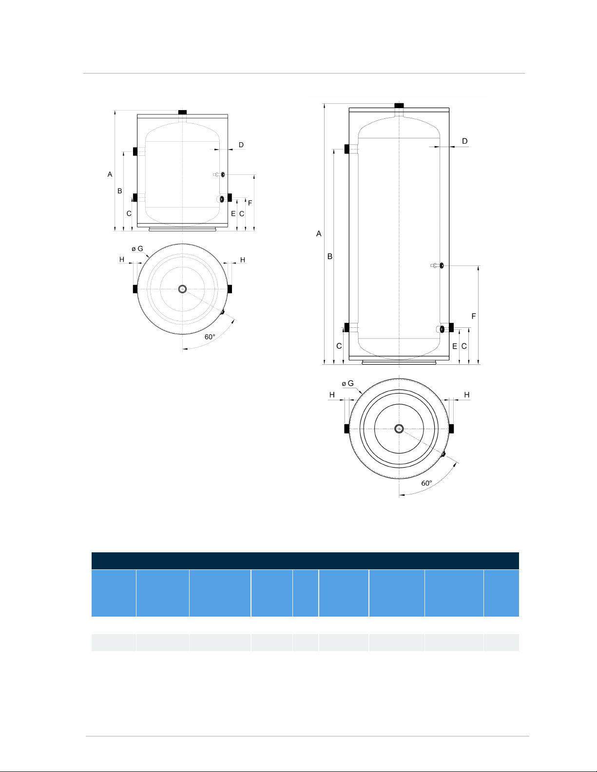
This tank is built with four connections: two connections for piping to the heating or cooling source
(on the left side), and two connections for piping to the distribution system (on top and on the right
side). The tank can serve as both a thermal buffer and a hydraulic separator to hydraulically
decouple the heating or cooling source from the distribution system.
The buffer tank is constructed with 444 stainless steel, 316 stainless steel connection fittings, 2"
thick foam insulation and a powder coated galvanized steel jacket. A 3/8" ID thermal well is located
mid-tank. Thermistors can be inserted 3" into the well. Alternatively, Honeywell L4006A Controls
can also be used.
Piping connections to both the heating or cooling source and the distribution system are 1 ½" NPT.
The drain is ¾" NPT.
The tank's top fitting should be piped to the distribution supply line and the air purger and vent, so
that the tank will be self venting, and no additional air vent is needed. Pipe the buffer tank so that the
heating or cooling source is hydraulically decoupled from the distribution system.
6
Section: IBTBuffer tanks


CAN IBC Technologies Inc. USA IBC Technologies USA Inc
A8015 North Fraser Way A1702 Taylor’s Lane
Burnaby, BC Canada V5J 5M8 Cinnaminson NJ 08077 USA
T604-877-0277 T856-877-0544
F604-877-0295 F856-735-5584
Toll Free: 1-844-HEAT-IBC/ 1-844-432-8422
www.ibcboiler.com
Information in this document is subject to change without notice. IBC assumes no
responsibility for changes made to the manual due to clerical errors, to regulation changes,
or to product development.
March, 2021 |120-369E
©IBC Technologies Inc. 2021
This manual suits for next models
1
Table of contents
Other IBC Boiler Supplies manuals