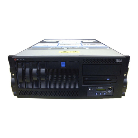
IBM 7311-D11 Use and care manual

Power Systems
5790 and 7311 model D11 removal and replacement
procedures


Power Systems
5790 and 7311 model D11 removal and replacement
procedures

Note
Before using this information and the product it supports, read the information in “Notices,” on
page 59, “Safety notices” on page v, the IBM Systems Safety Notices manual, G229-9054, and the
IBM Environmental Notices and User Guide, Z125–5823.
This edition applies to IBM Power Systems™servers that contain the POWER6®processor and to all associated
models.
© Copyright IBM Corporation 2008, 2009.
US Government Users Restricted Rights – Use, duplication or disclosure restricted by GSA ADP Schedule Contract
with IBM Corp.

Contents
Safety notices .................................v
5790 and 7311 model D11 removal and replacement procedures ...........1
Backplane ....................................2
Fan......................................10
PCI adapter ...................................12
Removing and replacing a PCI adapter contained in a cassette in an AIX partition that is powered on ....12
Removing and replacing a PCI adapter contained in a cassette in an IBM i partition that is powered on . . . 25
Removing and replacing a PCI adapter contained in a cassette in a Linux partition that is powered on ....37
Prerequisites for hot-plugging PCI adapters in a Linux partition................49
Verifying that the hot-plug PCI tools are installed on the Linux partition .............50
Power supply ..................................51
RIO bus adapter..................................53
RIO cable ....................................57
Appendix. Notices ...............................59
Trademarks ...................................60
Electronic emission notices ..............................60
Class A Notices .................................60
Terms and conditions ................................64
© Copyright IBM Corp. 2008, 2009 iii

iv Power Systems: 5790 and 7311 model D11 removal and replacement procedures

Safety notices
Safety notices may be printed throughout this guide:
vDANGER notices call attention to a situation that is potentially lethal or extremely hazardous to
people.
vCAUTION notices call attention to a situation that is potentially hazardous to people because of some
existing condition.
vAttention notices call attention to the possibility of damage to a program, device, system, or data.
World Trade safety information
Several countries require the safety information contained in product publications to be presented in their
national languages. If this requirement applies to your country, a safety information booklet is included
in the publications package shipped with the product. The booklet contains the safety information in
your national language with references to the U.S. English source. Before using a U.S. English publication
to install, operate, or service this product, you must first become familiar with the related safety
information in the booklet. You should also refer to the booklet any time you do not clearly understand
any safety information in the U.S. English publications.
German safety information
Das Produkt ist nicht für den Einsatz an Bildschirmarbeitsplätzen im Sinne§2der
Bildschirmarbeitsverordnung geeignet.
Laser safety information
IBM®servers can use I/O cards or features that are fiber-optic based and that utilize lasers or LEDs.
Laser compliance
All lasers are certified in the U.S. to conform to the requirements of DHHS 21 CFR Subchapter J for class
1 laser products. Outside the U.S., they are certified to be in compliance with IEC 60825 as a class 1 laser
product. Consult the label on each part for laser certification numbers and approval information.
CAUTION:
This product might contain one or more of the following devices: CD-ROM drive, DVD-ROM drive,
DVD-RAM drive, or laser module, which are Class 1 laser products. Note the following information:
vDo not remove the covers. Removing the covers of the laser product could result in exposure to
hazardous laser radiation. There are no serviceable parts inside the device.
vUse of the controls or adjustments or performance of procedures other than those specified herein
might result in hazardous radiation exposure.
(C026)
CAUTION:
Data processing environments can contain equipment transmitting on system links with laser modules
that operate at greater than Class 1 power levels. For this reason, never look into the end of an optical
fiber cable or open receptacle. (C027)
CAUTION:
This product contains a Class 1M laser. Do not view directly with optical instruments. (C028)
© Copyright IBM Corp. 2008, 2009 v

CAUTION:
Some laser products contain an embedded Class 3A or Class 3B laser diode. Note the following
information: laser radiation when open. Do not stare into the beam, do not view directly with optical
instruments, and avoid direct exposure to the beam. (C030)
Power and cabling information for NEBS (Network Equipment-Building System)
GR-1089-CORE
The following comments apply to the IBM servers that have been designated as conforming to NEBS
(Network Equipment-Building System) GR-1089-CORE:
The equipment is suitable for installation in the following:
vNetwork telecommunications facilities
vLocations where the NEC (National Electrical Code) applies
The intrabuilding ports of this equipment are suitable for connection to intrabuilding or unexposed
wiring or cabling only. The intrabuilding ports of this equipment must not be metallically connected to the
interfaces that connect to the OSP (outside plant) or its wiring. These interfaces are designed for use as
intrabuilding interfaces only (Type 2 or Type 4 ports as described in GR-1089-CORE) and require isolation
from the exposed OSP cabling. The addition of primary protectors is not sufficient protection to connect
these interfaces metallically to OSP wiring.
Note: All Ethernet cables must be shielded and grounded at both ends.
The ac-powered system does not require the use of an external surge protection device (SPD).
The dc-powered system employs an isolated DC return (DC-I) design. The DC battery return terminal
shall not be connected to the chassis or frame ground.
vi Power Systems: 5790 and 7311 model D11 removal and replacement procedures

5790 and 7311 model D11 removal and replacement
procedures
Use the removal and replacement procedures when you repair, maintain, or exchange your system parts.
Before you begin a replacement, perform these tasks:
1. If you are performing a replacement procedure that might put your data at risk, ensure, if possible,
that you have a current backup of your system or logical partition (including operating systems,
licensed programs, and data).
2. Review the installation or replacement procedure for the feature or part.
3. Note the significance of color on your system. Blue or terra-cotta on a part of the hardware indicates
a touch point where you can grip the hardware to remove it from or install it in the system, open or
close a latch, and so on. terra-cotta might also indicate that the part can be removed and replaced
with the system or logical partition power on.
4. Ensure that you have access to a medium, flat-blade screwdriver.
5. If parts are incorrect, missing, or visibly damaged, contact your service provider or next level of
support.
DANGER: When working on or around the system, observe the following precautions:
Electrical voltage and current from power, telephone, and communication cables are hazardous. To avoid
a shock hazard:
vConnect power to this unit only with the IBM provided power cord. Do not use the IBM provided
power cord for any other product.
vDo not open or service any power supply assembly.
vDo not connect or disconnect any cables or perform installation, maintenance, or reconfiguration of this
product during an electrical storm.
vThe product might be equipped with multiple power cords. To remove all hazardous voltages,
disconnect all power cords.
vConnect all power cords to a properly wired and grounded electrical outlet. Ensure that the outlet
supplies proper voltage and phase rotation according to the system rating plate.
vConnect any equipment that will be attached to this product to properly wired outlets.
vWhen possible, use one hand only to connect or disconnect signal cables.
vNever turn on any equipment when there is evidence of fire, water, or structural damage.
vDisconnect the attached power cords, telecommunications systems, networks, and modems before you
open the device covers, unless instructed otherwise in the installation and configuration procedures.
vConnect and disconnect cables as described in the following procedures when installing, moving, or
opening covers on this product or attached devices.
To Disconnect:
1. Turn off everything (unless instructed otherwise).
2. Remove the power cords from the outlets.
3. Remove the signal cables from the connectors.
4. Remove all cables from the devices
To Connect:
1. Turn off everything (unless instructed otherwise).
2. Attach all cables to the devices.
3. Attach the signal cables to the connectors.
4. Attach the power cords to the outlets.
5. Turn on the devices.
(D005)
© Copyright IBM Corp. 2008, 2009 1
Attention: Failure to follow the step-by-step sequence for FRU removal or installation may result in
FRU or system damage.
Use the following precautions whenever you handle electronic components or cables:
vUse the electrostatic discharge (ESD) kit and the ESD wrist strap when handling logic cards, SCMs,
MCMs, electronic boards, and disk drives.
vKeep all electronic components in the shipping container or envelope until you are ready to install
them.
vIf you remove, then reinstall an electronic component, temporarily place the component on an ESD pad
or blanket.
Backplane
Use this procedure to service the backplane.
1.
The component will be serviced non-concurrently.
Power should be removed from the unit. If this unit is powered on, power it off now. When the unit is completely
powered off, disconnect the AC input source by removing the power cord from the unit. Do not apply power to the
unit until directed to do so in this procedure.
2. Disconnect the I/O subsystem
1. From the rear of the rack, disconnect the
I/O subsystem's power cables from the
power distribution bus.
2. Remove the retaining screws (A) located
on the rear of the I/O subsystem unit.
3. Label and disconnect all of the cables
connected to the rear of the I/O
subsystem.
3. Remove the I/O subsystem
2Power Systems: 5790 and 7311 model D11 removal and replacement procedures

1. From the rear of the rack, pull the I/O
subsystem straight back until the
subsystem stops.
2. To allow the subsystem to move further to
the rear, press the stop latch (A).
3. Support the I/O subsystem as you pull it
toward the rear of the rack.
4. When the I/O subsystem is out of the
rack, place it on a stable work surface.
4. Remove the PCI adapter
1. Locate the slot from which you are
removing the adapter.
2. Disconnect any cables that are connected
to the adapter being removed.
3. Press the center of the handle (A) of the
PCI card cassette to release the latch, then
lower the handle completely.
4. When the handle is completely lowered,
push the gray locking cross bar (B).
5. Remove the PCI adapter
5790 and 7311 model D11 removal and replacement procedures 3

Carefully pull the PCI card cassette straight
out from the I/O subsystem. Take care not to
pull EMC gaskets from neighboring cassettes.
6. Remove the power supplies
1. Disconnect the power cord from the power
supply.
2. Unlatch the power supply handle (A) and
rotate the handle downward to unseat the
power supply.
3. Pull the power supply straight out from
the I/O subsystem.
4. Repeat these steps to remove the other
power supply.
7. Remove the I/O subsystem service access cover
4Power Systems: 5790 and 7311 model D11 removal and replacement procedures

1. Loosen the two captive thumbscrews (A)
located at the rear of the cover.
2. From the rear of the I/O subsystem, lift
the cover and slide it backwards until the
front disengages.
3. Lift the cover off the I/O subsystem unit.
8. Remove the RIO bus adapter
1. Squeeze the release latches (A) to release
them from the card and rotate in the
direction shown.
2. Carefully pull the card straight up and out
of the slot.
9. Remove the I/O backplane
5790 and 7311 model D11 removal and replacement procedures 5

Note: The I/O backplane and the SPCN riser
card are replaced as a pair.
1. Disconnect the fan cable (E) from the I/O
backplane.
2. Rotate the cable tray up and out of the
way.
3. Remove the two screws (A) that hold the
SPCN connector card and remove it from
the I/O backplane.
4. Remove the top adapter cassette guides.
5. Remove the screws (B) that hold the PCI
adapter mounting-guide and remove the
guides from the I/O backplane.
6. Move the Power Bulkhead out of the way
by removing two side screws, then
rotating the bottom of the bulkhead up
then out to slide it off the guide pins. Set
the bulkhead on top of the system with
the fan cable still attached.
7. Remove the screws (C) that secure the I/O
backplane to the subsystem chassis.
8. Lift the I/O subsystem backplane, with
the attached VPD module (D), straight up
and out of the subsystem chassis.
10. Install the I/O backplane
1. Place the I/O subsystem backplane
assembly into the chassis. Align the
backplane with the mounting screw holes.
2. Position the PCI adapter mounting-guides
on the I/O backplane and install the
screws (C) to secure the mounting-guides.
3. Secure the backplane with the remaining
mounting screws (B) removed earlier.
4. Install the new SPCN connector card on
the new I/O subsystem backplane using
the screws (A) removed earlier.
Note: The I/O backplane and the SPCN
connector card are replaced as a pair.
5. Reconnect the fan cable (E) to the I/O
backplane.
11. Install the RIO bus adapter
6Power Systems: 5790 and 7311 model D11 removal and replacement procedures

1. Carefully push the card straight down into
the slot.
2. Rotate the release latches (A) in the
direction shown to secure the card.
12. Install the power supplies
1. Push the power supply straight into the
I/O subsystem.
2. Rotate the power supply handle (A)
upward to seat the power supply then
latch the power supply handle.
3. Connect the power cord to the power
supply.
4. Repeat these steps to install the other
power supply.
13. Install the I/O subsystem service access covers
5790 and 7311 model D11 removal and replacement procedures 7

1. Position the cover over the rear of the I/O
subsytem.
2. Align the service access cover with the
I/O subsystem so that the front portion of
the cover engages with the front part of
the I/O subsystem chassis. The flanges on
the left and right sides of the cover should
be on the outside of the I/O subsystem
chassis.
3. Hold the cover down and slide it forward
toward the front of the I/O subsystem.
The front edge of the service access cover
engages the front portion of the I/O
subsystem.
4. Push in to engage and then tighten the
thumbscrews (A) located at the rear of the
cover.
14. Install the PCI adapter
1. Press the center of the handle (A) of the
PCI card cassette to release the latch, then
lower the handle completely.
2. When the handle is completely lowered,
push the gray locking cross bar (B).
15. Install the PCI adapter
8Power Systems: 5790 and 7311 model D11 removal and replacement procedures

1. Hold the assembly straight on and level
with the slot.
2. Align the bottom edge of the PCI cassette
cover (A) with the PCI card guide rail (B)
on the I/O backplane.
3.
Note: If there is a cassette to the left of the
one you are installing, align the ridge on
the cover with the 'tick' in the notch of the
neighboring cassette.
4. Slide the cassette partially into the guide.
5. Ensure the dovetail (C) on the top track
aligns with its mating component(s) on
both sides.
16. Install the PCI adapter
1. When the cassette is fully inserted, prepare
to activate the handle by lowering the
gray locking bar (B). Lift the handle (A) all
the way up until you hear a click. The PCI
Card should be completely seated. Note:
To enable proper insertion of the adapter,
some minor forward or backward
movement of the PCI adapter cassette
might be necessary.
2. Set the color slide (C) to blue.
17. Place the I/O subsystem into the operating position
5790 and 7311 model D11 removal and replacement procedures 9

1. From the rear of the rack, insert the I/O
subsystem into the position from which it
was removed. The end of the I/O
subsystem that has the power supplies
goes toward the front of the rack.
2. Support the I/O subsystem as you push it
toward the front of the rack.
3. Install the retaining screws (A) in the rear
of the I/O subsystem unit.
4. Reconnect the cables to the rear of the I/O
subsystem.
18. Configuring I/O enclosures
View and change various I/O enclosure attributes. After the server firmware has reached the
standby state, you can configure I/O enclosure attributes as follows:
vList the status, location code, rack address, unit address, power control network identifier, and the
machine type and model of each enclosure in the system.
vChange the identification indicator state on each enclosure to identify or off.
vUpdate the power control network identifier, enclosure serial number, and the machine type and
model of each enclosure.
vChange the identification indicator state of the SPCN firmware in a enclosure to Enable or Disable.
vRemove rack and unit addresses for all inactive enclosures in the system.
To perform this operation, your authority level must be one of the following:
vAdministrator
vAuthorized service provider
To configure I/O enclosures, do the following:
a. On the ASMI Welcome pane, specify your user ID and password, and click Log In.
b. In the navigation area, expand System Configuration and select Configure I/O Enclosures.
c. Select the enclosure and the desired operation. If you select Change settings, click Save setting to
complete the operation.
19.
Go to Verification Procedures.
Fan
Use this procedure to service the fan.
1.
The component will be serviced concurrently. Power should not be removed from the unit.
10 Power Systems: 5790 and 7311 model D11 removal and replacement procedures

2.
1. Locate the cooling fan assembly on the
front of the I/O subsystem.
2. Unscrew the thumbscrew (A) that holds
the fan into the I/O subsystem.
3. Pull the fan assembly straight out until it
is clear of the I/O subsystem.
3.
1. Position the fan with the connector (B)
(located on the fan housing) facing in
toward the I/O subsystem.
2. Insert the replacement fan assembly into
the I/O subsystem as far as possible.
3. Screw in the thumbscrew (A) to hold the
fan in position.
4. Verify the repair
Go to Verification Procedures.
5790 and 7311 model D11 removal and replacement procedures 11

PCI adapter
Use this procedure to service a PCI adapter.
If your system is managed by the Hardware Management Console (HMC), use the HMC to complete the
steps for removing and replacing a PCI adapter. For instructions, see Removing a part using the
Hardware Management Console.
The PCI adapter is serviced concurrently. Select the procedure below based on your operating system.
If you are doing a concurrent repair using the AIX®operating system, go to Removing and replacing a PCI adapter
contained in a cassette in an AIX partition that is powered on.
If you are doing a concurrent repair using the IBM i operating system, go to Removing and replacing a PCI adapter
contained in a cassette in an IBM i partition that is powered on.
If you are doing a concurrent repair using the Linux®operating system, go to Removing and replacing a PCI adapter
contained in a cassette in a Linux partition that is powered on.
Removing and replacing a PCI adapter contained in a cassette in an
AIX partition that is powered on
Use this procedure to remove and replace a PCI adapter contained in a cassette with the power on.
Procedures performed on a PCI adapter in an AIX partition that is powered on, also known as hot-plug
procedures, require the system administrator to take the PCI adapter offline prior to performing the
operation. Before taking an adapter offline, the devices attached to the adapter must be taken offline as
well. This action prevents a service representative or user from causing an unexpected outage for system
users.
To remove and replace an adapter, do the following steps:
1. Determine the location of the PCI adapter in the system.
2. Record the slot number and location of each adapter being removed. Adapter slots are numbered on
the rear of the system unit.
3. Ensure that any processes or applications that might use the adapter are stopped.
4. Enter the system diagnostics by logging in as root user or as the CE login user, then type diag at
AIX command line.
5. When the DIAGNOSTIC OPERATING INSTRUCTIONS menu is displayed, press Enter.
6. At the FUNCTION SELECTION menu, select Task Selection, and then press enter.
7. At the Task Selection list, select Hot Plug Manager, and then select PCI Hot Plug Manager.
8. Select Unconfigure a Device, and then press Enter.
9. Press F4 (or Esc+4) to display the Device Names menu.
10. Select the adapter you are removing in the Device Names menu.
11. Use the Tab key to answer YES to Keep Definition. Use the Tab key again to answer YES to
Unconfigure Child Devices, then press Enter.
12. The ARE YOU SURE screen is displayed. Press Enter to verify the information. Successful
unconfiguration is indicated by the OK message displayed next to the Command field at the top of
the screen.
13. Press F3 (or Esc +3) twice to return to the Hot Plug Manager menu.
14. Select replace/remove PCI Hot Plug adapter.
15. Select the slot that has the device to be removed from the system.
12 Power Systems: 5790 and 7311 model D11 removal and replacement procedures
This manual suits for next models
1
Table of contents
Other IBM Computer Hardware manuals

IBM
IBM Power System S914 Instruction Manual

IBM
IBM System x Education M5000 Series User manual

IBM
IBM QuickOn for Running Windows User manual

IBM
IBM 2740-1 User guide

IBM
IBM 1620 1 User manual

IBM
IBM Power S1014 User manual

IBM
IBM 5280 Manual

IBM
IBM 55PUS8118 SCSI-2 User manual

IBM
IBM p5 550 Installation guide

IBM
IBM A2 User manual

IBM
IBM 09N4076 User manual

IBM
IBM 3290 T Manual instruction

IBM
IBM ATA 133 User manual

IBM
IBM 3270 User manual

IBM
IBM N2225 User manual

IBM
IBM 4767 User manual

IBM
IBM 3745 Series Instruction Manual

IBM
IBM SAN Volume Controller 2145-CF8 Manual

IBM
IBM PCI Cryptographic Coprocessor Guide

IBM
IBM Power Systems 9223-22S User manual