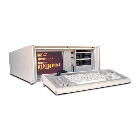
IBM System/32 Reference manual

· / ( (
(
(
\
-
-
-
---
-
--
---..
-~-
---
--
------
-
----
===~==
~
=Maintenance Library
SYSTEM/3~
Introduction and
Maintenance
SY31-0373-4

PREFACE
This
manual
contains
introductory
and
maintenance
information,
and
installation
instructions
for
IBM
System/32.
The
maintenance
information
includes
checks,
adjustments,
and
removals
and
replacements.
Other
manuals
to
be
used
with
this
one
are:
•
IBM
System/32 Operator's Guide, GC21-7591
•
IBM
Diskette
For
Standard Data Interchange,
GA21-9182
•
IBM
System/32 Functions Reference Manual,
GA21-9176
•
IBM
System/32 System ControlProgram
Reference Manual, GC21-7593
For
theory
of
operation
and
circuit
detail,
see
IBM
Maintenance Library, System/32 Theory
Diagrams,
SY31-0346.
In
addition,
refer
to
the
System/32 Diagnostic
User's Service Guide
for
further
information
on
system
diagnostic
procedures.
Fifth Edition (May 1977)
This
is
a major revision
of,
and
obsoletes,
SY31-0373-3.
Extensive changes have
been
made
throughout,
and
this
publication
should
be reviewed
in
its
entirety.
Changes
are
periodically
made
to
the
information
herein;
any
such
change
will be
reported
in
sub-
sequent
revisions
or
technical newsletters.
A
Reader's
Comment
Form
is
at
the
back
of
this
publication.
If
the
form
is
gone,
address
your
comments
to
IBM
Corporation,
Publications,
Department
245,
Rochester,
Minnesota
55901.
©Copyright
International Business Machines
Corporation
1975,1976,1977

CONTENTS
LIST OF
ABBREVIATIONS.
xi 2.1.15 Write Safety
2-7
Data Unsafe Conditions
2-7
CE
SAFETY
PRACTICES. xiii File
Ready.
2-7
Disk Speed.
2-7
1.0.0 INTRODUCTION
1-1
Power Up
2-7
1.1.0 DESCRIPTION
1-1
2.1.16
Seek
Operation 2-8
1.2.0 BASIC CONFIGURATION 1-2 2.1.17 Recalibrate Operation 2-8
1.3.0 SYSTEM
DATA
FLOW 1-3 2.1.18 Behind Home . 2-8
1.4.0 PROCESSING
UNIT
DATA
FLOW 1-4 2.1.19
Servo
Track Following . 2-9
1.5.0
CHANNEL
DATA
FLOW.
1-5 2.2.0
MAl
NTENANCE . 2-10
1.6.0 SYSTEM MICROPROGRAM. 1-6 2.2.1 Card Sockets 2-10
1.7.0 CONTROL
STORAGE.
1-7
2.2.2 Disk Enclosure (DE) 2-12
1.8.0
FUNCTIONAL
UNITS.
1-8 2.2.3 Disk Drive Motor 2-14
1.8.1 Main Storage
(MS)
1-8 2.2.3.1 Old Style Motor 2-14
1.8.2 Control Storage
(CS)
1-8 2.2.3.2 New Style Motor . 2-16
1.'8.3 Storage Address Register (SAR) . 1-8 2.2.3.3 Motor Start Relay 2-16.2
1.8.4 Micro Operation Register
(MaR)
1-8 2.2.4 Brake Assembly
and
Brake Coil
1.8.5
Process
Condition Register (PCR) 1-8
Assembly.
2-16.4
1.8.6 Storage Data Register
(SD
R)
. 1-8 2.2.5 Brake Assembly 2-18
1.8.7 X and Y
Registers
1-8 2.2.6 Motor Antistatic Brush . 2-20
1.8.8
Arithmetic
Logical
Unit
(ALU)
1-8 2.2.7 Spindle Antistatic Brush 2-20
1.8.9 Local Storage Registers (LSR) 1-9 2.2.8 Disk
Speed
Transducer .
2-21
1.9.0
INITIAL
SYSTEM
CHECKOUT.
1-10 2.2.9 Motor Tension Spring 2-23
1.10.0 EVENT INDICATOR
SEQUENCE.
1-10 2.2.10 Shock Mount (Top One) 2-24
1.11.0 MICRO
INTERRUPTS.
1-11
2.2.11 Shock Mounts (Bottom Two) 2-24
1.12.0 SYSTEM
PARITY
CHECKING
AND
2.3.0 CABLE
AND
CARD
LOCATIONS.
2-26
PARITY
GENERATION.
1-12
1.13.0 I/O
PARITY
CHECKING
AND
3.0.0
33FD
DISKETTE
DRIVE.
3-1
GENERATION.
1-13 3.1.0 THEORY
3-1
1.14.0 OPERATION RETRY
AND
ERROR 3.1.1 33FD Description 3-2
LOGGING 1-14 3.1.2 Diskette Format . 3-4
1.15.0
LOCATIONS.
1-15 3.1.3 Operating
Sequences
3-6
1.16.0 BOARD PIN LOCATIONS 1-16 Initialization 3-6
Seek.
3-6
2.0.0 DISK
DRIVE
2-1
Read
or
Write . 3-6
2.1.0
THEORY
2-1
3.1.4 Read/Write Circuit Principles. 3-8
2.1.1 Introduction
2-1
3.2.0
MAl
NTENANCE . 3-9
2.1.2 Subframe
2-1
3.2.1
Machine Safety 3-9
2.1.3
Grounding.
2-1
3.2.2 Tools 3-9
2.1.4 Disk Enclosure 2-2 3.2.3
Head
Cleaning Tools (3.2.10) . 3-9
2.1.5 Disk Spindle
2-2
3.2.3.1
Pressure
Pad
Replacement
Kit
3-9
2.1.6 Transducer. 2-2 3.2.4 Diskette
Care
. 3-10
2.1.7 Actuator 2-3 Handling 3-10
2.1.8 Actuator Lock 2-3 Long Term Storage 3-10
2.1.9 Actuator Position Indicator 2-3 Shipping and Receiving. 3-10
2.1.10 Circuitry Location 2-3 Inserting and Removing the
2.1.11 Disk Description .
2-4
Diskette 3-10
Data Tracks 2-4 3.2.5 33FD Diskette Drive
3-11
Servo Tracks 2-4 3.2.6 Latch Assembly 3-12
2.1.12 Landing Zone (LZ) 2-4 3.2.7 Collet 3-12
2.1.13 Guard
Band
(GB) . 2-4 3.2.8 Cover Assembly 3-12
2.1.14 Motor and Brake . 2-5 3.2.9
Pressure
Pad
Actuator 3-13
Sector Format 2-6 3.2.10
Head
and
Pressure
Pad
Cleaning 3-13
Contents iii
TNL:
SN31-0487
to
SY31-0373-4 (25 Nov 77)

iv
3.2.10.1 Leadscrew Dust Cover
(if
installed) 3-13 4.1.4
Input/Output
Lines (continued)
3.2.11 Leadscrew and
Head
Carriage Stop Ribbon (A) 4-13
Assembly 3-14 Hammer Check 1-22 (also 23-44
and
3.2.12 Drive Motor 3-15 45-66)
(P)
4-13
3.2.13 Hub Assembly 3-17 Activate
Paper
Clamps (A) 4-13
3.2.14 Drive Pulley 3-17 Carriage Advance
(P)
4-13
3.2.15 Belt Tracking 3-17 Home
Pulse
(P)
4-13
3.2.16 Idler Assembly 3-17 Throat Closed Switch
(P)
4-13
3.2.17 ReadIWrite
Head
3-18 Cover Closed Switch
(P)
4-13
3.2.18 Leadscrew
Wheel
3-19 Forms
Sensed
Switch
(P)
4-13
3.2.19 Lower
Limit
Stop 3-20 Printer Thermal Switch
(P)
4-13
3.2.20 Upper
Limit
Stop 3-20 4.1.5 Circuit
Cards
(50, 100, and 155 Ipm) 4-14
3.2.21 Stepper Motor and Bracket
3-21
Hammer Driver 4-14
3.2.22 Phototransistor 3:22 Motors/Solenoid Driver 4-14
3.2.23 Light Emitting Diode (LED) 3-23 Control Card 4-14
3.2.24 File Control
Card
3-24 4.1.6 Card
Gate
Connector Details
Test Points 3-24 (50, 100, 155 Ipm) 4-15
File Card
Pin
Assignment 3-24 4.1.7 Printer Power
Plugs
(50, 100, and
File Control
Card
Socket
Pins
3-25 1551pm) 4-15
4.1.8
Pin
Reversal
In
Cables
4-16
4.0.0 BELT PRINTER
4-1
4.2.0 MAINTENANCE-(50, 100, 1551pm) 4-17
4.1.0
THEORY
4-1
4.2.1 Printer Cover and Divider Removal
and
4.1.1 Principles
of
Printing (50, 100, and Replacement 4-17
1551pm) 4-2 4.2.1.1 Printer Cover Grounding 4-17
4.1.2 Functional Components 4.2.2 Interlock Switch Description 4-18
(50, 100, and 155 Ipm) 4-5 4.2.2.1 Cover Interlock Switch 4-18
Type Belt Transducer 4-5 4.2.2.2 Print
Unit
(Throat) Interlock Switch 4-19
Ribbon Drive 4-6 4.2.2.3 End-of-Forms Interlock Switch 4-19
Type Belt Drive 4-6 4.2.3 Thermal Switch 4-20
Carriage 4-7 4.2.4
Fan
Assembly 4-21
Throat 4-10 4.2.5
24V
Relay (Contactor
Kl)
4-21
Paper
Clamps 4-10 4.2.6 Diode 01 Service Check 4-22
4.1.3 Checking (50, 100, and 155 Ipm) 4-11 4.2.7 Motor Checkout Procedure (50, 100, and
Forms
Jam
Check 4-11 1551pm) 4-23
Belt
Speed
Check 4-11 Type Belt
Motor
(50, 100, and
Carriage Sync Check 4-11 1551pm) 4-23
Coil Current Check 4-11 Carriage
Motor
(50, 100, and
Belt Sync Check 4-11 1551pm) 4-24
Emitter Check 4-11 4.2.8 Motor
Phase
Capacitor (50, 100,
and
Data Check
4-11
1551pm) 4-25
Hammer Parity Check 4-11 4.2.9 Motor and
Paper
Clamp Resistor (50, 100,
End
of
Forms Check 4-11 and 1551pm) 4-25
Throat
Closed
Check 4-11 4.2.10 Print
Unit
Assembly (50, 100, and
Cover
Closed
Check
4-11
1551pm) 4-26
Unprintable Character Check
4-11
4.2.10.1 Print Units With Pivot
Screws
4-26
4.1.4
Input/Output
Lines (50, 100, and 4.2.10.2 Print Units With Pivot
Pins
4-28
1551pm) 4-12 4.2.10.3 Print
Unit
Stop Screw
POR/Printer
Reset
(A) 4-12
(50,100,
and 1551pm) 4-30
Close
(+24V) Contactor (A) 4-12 4.2.11 Platen
Gap
(50, 100, and 155 Ipm)
4-31
Belt Go (A) 4-12 4.2.12 Platen (50, 100, and 1551pm) 4-33
1
Belt Motion
(P)
4-12 4.2.13 Type Belt (50, 100, and 155 Ipm) 4-35
PSS
(Subscan)
(P)
4-12 Static Test
for
Type Belt Binds 4-35
IMPSS
(Impression Singleshot)
(P)
4-12 Dynamic Test
for
Type Belt Binds 4-35
Fire Hammer (A) 4-12 4.2.14 Type Belt Drive Pulley Assembly 4-36
Carriage
Go
(A) 4-13 4.2.15 Type Belt Motor
'4-37
4.2.16 Type Belt Positioning Rollers 4-37

. .
4.2.17 Type Belt Idler
~ulley
4-38 4.2.45.3 Print Units With Pivot
Pins
and
One
Paper
4.2.18 Type Belt Idler Pulley Pivot Assembly 4-38 Clamp Engaging Lever 4-68
4.2.18.1 Without
Clevis
(Old Style) 4-38 4.2.46 Forms
Jam
Detection Device 4-70
4.2.18.2 With
Clevis
(New Style) 4-38 4.2.47 Examples
of
Incorrect Printing (50, 100,
4.2.19 Transducer Assembly (50, 100, and and 1551pm)
4-71
1551pm) 4-39 4.2.48 Lower Forms Guide
To
Hammer Bar
4.2.20 Transducer 4-40 Adjustment 4-72
4.2.21 Impression Singleshot Potentiometer 4.2.49 Lower
Paper
Guide
To
Hammer
(50, 100, and 155 Ipm)
4-41
Clearance 4-72
4.2.22 Transducer Position (Character
Cutoff)
4-42 4.3.0 LOCATIONS (50, 100,
and
1551pm) 4-73
4.2.23 Hammer Flight Time (50, 100, and 4.3.1 Back View 4-73
1551pm) 4-42 4.3.2 Front View 4-74
4.2.24 Hammer Coil (50, 100, and 155 Ipm) 4-43 4.3.3 Right
Side
4-75
4.2.25 Hammer (50, 100,
and
155 Ipm) 4-44 4.3.4 Left
Side
4-76
4.2.26 Hammer Block Assembly (50, 100, and 4.3.5
Card
Gate
(50, 100, and 155 Ipm) 4-77
1551pm) 4-45 4.3.6
Card
and
I/O
Cables
(50, 100, and
4.2.27 Ribbon Drive Description 4-46 1551pm) 4-78
4.2.28 Ribbon
Cassette
(50, 100,
and
155 Ipm) 4-47 4.4.0 OSCILLOSCOPE FIGURES
(50,100,
and
4.2.29 Ribbon Drive Assembly 4-47 1551pm) 4-79
4.2.30 Ribbon Drive Clutch 4-48 4.5.1 Principles
of
Printing (285 Ipm) 4-82
4.2.31 Ribbon Drive Belt 4-49 4.5.2 Functional Components
(285Ipm)
4-85
4.2.32 Ribbon Solenoid 4-50 Ribbon Drive 4-86
4.2.33 Ribbon Drive Rolls and Idler Rolls Type Belt Drive 4-86
(50, 100, and 1551pm) 4·51 Carriage 4·87
4.2.34 Ribbon
Drag
(50, 100,
and
155 Ipm) 4·51 Throat 4·90
4.2.35 Ribbon Tracking (50, 100,
and
1551pm) 4·52
Paper
Clamps 4·90
4.2.35.1 For Ribbon Shields Without Guides 4·52 4.5.3 Checking (285 Ipm) 4·91
4.2.35.2 For Ribbon Shields With Guides 4·52 Forms Jam Check 4·91
4.2.36 Ribbon Shield (50, 100, and 155 Ipm) 4·52.1 Belt
Speed
Check 4·91
4.2.37 Tractor Drive Shaft 4·53 Carriage Sync Check
4-91
4.2.38 Tractor Cover 4·53 Coil Current Check 4·91
4.2.39 Carriage Tractor/Vernier
!Tractor Drive Belt Sync Check 4·91
Shaft 4·54 Emitter Check 4·91
4.2.40 Carriage Motor 4·55 Data Check 4·91
4.2.41 Carriage Drive Belt 4·55 Hammer Parity Check 4·91
4.2.42 Upper
Paper
Clamp 4·56 End
of
Forms Check 4·91
4.2.43 Upper
Paper
Clamp Assembly 4·57 Throat
Closed
Check 4·91
4.2.44 Lower
Paper
Clamp (50, 100, and Cover
Closed
Check 4·91
1551pm)
4·58
Unprintable Character Check 4·91
4.2.44.1
Two
Coil Clamp with Two Engaging 4.5.4
Input/Output
Lines (285 Ipm) 4·92
Levers
4·58 POR/Printer
Reset
(A) 4·92
4.2.44.2 Single Coil Clamp With
One
Engaging
Close
(+24V) Contactor (A)
Lever 4·60 Belt
Go
(A) 4·92
4.2.44.3 Clamp Assembly Removal (Single Coil Belt Motion
(P)
4·92
Clamp With
One
Engaging Lever) 4·62
PSS
(Subscan)
(P)
4·92
4.2.44.4 Clamp
Bar
Removal (Single Coil Clamp
IMPSS
(Impression Singleshot)
(P)
4·92
With
One
Engaging Lever) 4·62 Fire Hammer (A) 4·92
4.2.44.5 Coil Assembly Removal (Single Coil 4.5.5 Circuit
Cards
(285 Ipm) 4·94
Clamp With
One
Engaging Lever) 4·62 Hammer Driver 4·94
4.2.45 Forms Tension Assembly (50, 100, and Motors/Solenoid Driver 4·94
1551pm) 4·64 Control Card 4·94
4.2.45.1 Print Units
with
Pivot
Screws
and
Two
4.5.6
Card
Gate Connector Details
Paper
Clamp Engaging
Levers
4·64
(285Ipm)
4·95
4.2.45.2 Print Units with Pivot
Pins
and Two
Paper
4.5.7 Printer Power
Plugs
(285 Ipm) 4·95
Clamp Engaging
Levers
4·66 4.5.8 Pin
Reversal
In
Cables
4·96
Contents v
TNL:
SN31·0487
to
SY31-0373-4 (25 Nov 77)

vi
4.6.0
MAINTENANCE
4-97 4.6.41 Carriage Drive Belt 4-136
4.6.1 Printer Cover and Divider Removal and 4.6.42 Upper
Paper
Clamp 4-137
Replacement 4-97 4.6.43 Upper
Paper
Clamp Assembly 4-138
4.6.1.1 Printer Cover Grounding 4-97 4.6.44 Lower
Paper
Clamp (285 Ipm) 4-139
4.6.2 Interlock Switch Description 4-98 4.6.44.1 Two Coil Clamp with
Two
Engaging
4.6.2.1 Cover Interlock Switch 4-98
Levers
4-139
4.6.2.2 Print
Unit
(Throat) Interlock Switch 4-99 4.6.44.2 Single Coil Clamp With
One
Engaging
4.6.2.3 End-of-Forms Interlock Switch 4-99 Lever 4-142
4.6.3 Thermal Switch 4-100 4.6.44.3 Clamp Assembly Removal (Single Coil
4.6.4
Fan
Assembly 4-101 Clamp
with
One
Engaging Lever 4-144
4.6.5 24V Relay (Contactor K1) 4-101 4.6.44.4 Clamp
Bar
Removal (Single Coil Clamp
4.6.6 Diode D1 Service Check 4-102 with One Engaging Lever) 4-144
4.6.7 Motor Checkout Procedure
(285Ipm)
4-103 4.6.44.5 Coil Assembly Removal (Single Coil
Type Belt Motor
(285Ipm)
4-103 Clamp
with
One Engaging Lever) 4-144
Carriage Motor (285 Ipm) 4-104 4.6.45 Forms Tension Assembly
(285Ipm)
4-146
4.6.8 Motor
Phase
Capacitor
(285Ipm)
4-105 4.6.45.1 Print Units
with
Two
Paper
Clamp
4.6.9 Motor and
Paper
Clamp Resistor
Engaging
Levers
4-146
(285Ipm)
4-105 4.6.45.2 Print Units
with
One
Paper
Clamp
4.6.10 Print
Unit
Assembly (285 Ipm) 4-106
Engaging
Lever 4-148
4.6.10.1 Print
Unit
Stop Screw (285 Ipm) 4-108 4.6.46 Forms
Jam
Detection Device 4-150
4.6.11 Platen
Gap
(285 Ipm) 4-109 4.6.47 Examples
of
Incorrect Printing
4.6.12 Platen (285 Ipm) 4-112
(285Ipm)
4-151
4.6.13 Type Belt (285 Ipm) 4-113 4.6.48 Lower Forms Guide
To
Hammer
Bar
Static Test
for
Type Belt Binds 4-113 Adjustment 4-152
Dynamic Test
for
Type Belt Binds 4-113 4.6.49 Lower
Paper
Guide
To
Hammer
4.6.14 Type Belt Drive Pulley Assembly 4-114 Clearance 4-152
4.6.15 Type Belt
Motor
4-115 4.7.0 LOCATIONS
(285Ipm)
4-153
4.6.16 Type Belt Positioning Rollers 4-115 4.7.1 Back View 4-153
4.6.17 Type Belt Idler Pulley (285 Ipm) 4-116 4.7.2
Front
View 4-154
4.6.18 Type Belt Idler Pulley Pivot Assembly 4-116 4.7.3 Right
Side
4-155
4.6.19 Transducer Assembly (285 Ipm) 4-117 4.7.4 Left
Side
4-156
4.6.20 Transducer 4-118 4.7.5
Card
Gate (285 Ipm) 4-157
4.6.21 Impression Singleshot Potentiometer 4.7.6 Card and I/O
Cables
(285 Ipm) 4-158
(285Ipm)
4-119 4.8.0 OSCILLOSCOPE FIGURES
(285Ipm)
4-159
4.6.22 Transducer Position (Character
Cutoff)
4-120
4.6.23 Hammer Flight Time (285 Ipm) 4-120 5.0.0 DISPLAY
UNIT
5-'
4.6.24 Hammer Coil
(285Ipm)
4-121 5.1.0 THEORY
5-1
4.6.25 Hammer
(285Ipm)
4-123
5.1.1
Formation
of
Characters
5-1
4.6.26 Hammer Block Assembly (285 Ipm) 4-124 5.2.0
FUNCTIONAL
CIRCUITS 5-2
4.6.27 Ribbon Drive Description 4-125
5.2.1
High Voltage Oscillator
5-2
4.6.28 Ribbon
Cassette
(285Ipm)
4-126 5.2.2 Brightness Control 5-2
4.6.29 Ribbon Drive Assembly 4-126 5.2.3 Video Dot
Amplifier
5-3
4.6.30 Ribbon Drive Clutch 4-127 5.2.4 Wiggle
Sweep
Circuit
5-3
4.6.31 Ribbon Drive Belt 4-128 5.2.5 Horizontal Deflection Control
5-3
4.6.32 Ribbon Solenoid 4-129 5.2.6 Vertical Line Control 5-3
4.6.33 Ribbon Drive Rolls and Idler Rolls 5.3.0 OPERATION
5-4
(285Ipm)
4-130 5.4.0
MAINTENANCE
5-5
4.6.34 Ribbon Drag (285 Ipm) 4-130
5.4.1
CRT Safety 5-5
4.6.35 Ribbon Tracking (285 Ipm) 4-131 Protective Equipment 5-5
4.6.36 Ribbon Shields (285 Ipm) 4-132 Cathode
Ray
Tubes-Safe Handling 5-5
4.6.37 Tractor Drive Shaft 4-134 Transportation Handling 5-5
4.6.38 Tractor Cover 4-134 Storage 5-5
4.6.39 Carriage Tractor/Vernier/Tractor Drive Testing 5-5
Shaft 4-135 Defective CRT Disposition 5-5
4.6.40 Carriage Motor 4-136 5.4.2 Display Assembly
5-7

5.4.3
5.4.4
6.0.0
6.1.0
6.1.1
6.1.2
6.1.3
6.1.4
6.2.0
6.3.0
6.3.1
6.3.2
6.3.3
6.3.4
6.3.5
7.0.0
7.1.0
7.1.1
7.1.2
7.1.3
7.1.4
7.1.5
7.1.6
7.1.7
7.1.8
7.2.0
7.2.1
(
Yoke Adjustment
MAP/Diagnostic Test Display Patterns
KEYBOARD
THEORY
Introduction
Key Modules
Key Detection
Clicker
Shift.
Character Repeat.
Character Storage
Control.
Input
Lines
Basic Oscillator
Repeat
Oscillator.
Error.
Busy Tone
Output
Lines
Kbd Go .
Input
Lines
Bit
Lines
Key B
it
Codes.
FUNCTION KEYS
MAINTENANCE.
Keyboard
Assembly.
Key Module
Space
Bar
Flyplate Replacement
CODE
Key.
CONSOLES
OPERATOR
CONTROL
PANEL
CONTROLS.
LOAD
Key/Light
START
Key/Light
POWER
ON/OFF
Switch
STOP
Key/Light
.
KEYBD
RDY
(Keyboard Ready)
Light
PROC
CH
K (Processor Check) Light
PWR
CH
K (Power Check)
Light.
TH
CH
K (Thermal Check)
Light.
CE
CONTROL
PANEL .
MODE SELECTOR Switch
PROC RUN
INSN STEP/DPLY LSR
I
I
\
LSR Subdivision and Micro
Interrupt
Levels
AL
TERMAR
IRPT
ALTER
STOR
DPLY
STOR
INSN STEP/DPLY
CH
KS
Processing
Unit
Error Byte
(High-Order) .
Port Error Byte (Low-Order Byte)
INSN STEP/DPLY
PCR
SYS INSN
STEP.
(
5-7
5-8
6-1
6-1
6-1
6-1
6-1
6-1
6-1
6-1
6-1
6-2
6-2
6-2
6-2
6-2
6-2
6-2
6-2
6-2
6-3
6-4
6-7
6-7
6-7
6-7
6-8
6-8
7-1
7-2
7-2
7-2
7-2
7-2
7-2
7-2
7-2
7-2
7-3
7-3
7-3
7-3
7-3
7-4
7-4
7-4
7-5
7-5
7-5
7-5
7-5
"
7.2.2 IMPL-IPL Switches
7-6
IMPL Switch
7-6
IPL
Switch.
7-6
7.2.3 PROC
INTERRUPT
Lights
7-6
7.2.4 RESET Key
7-6
7.2.5
ADDRESS/DATA
DISPLAY/DATA
Switches
7-7
7.2.6 CLOCK
Light.
7-7
7.2.7 FORCE CLOCK Switch
7-7
7.2.8 CHECK Switch
7-7
7.2.9
CE
START
Key
7-7
7.2.10 LAMP TEST
Switch.
7-7
7.2.11
DISPLAY
INTENSITY
Control
7-7
7.2.12 STOR
SE
L Switch
7-7
7.2.13
PWR
FAULT
DPLY Switch and
DPLY
PWR
CHK
Key
7-8
7.2.14
ADD
COMP Switch
7-8
RUN
Position.
7-8
STOP Position
7-8
7.2.15 Feature Switches
7-9
COMM DPL Switch
7-9
8.0.0 POWER SUPPLIES
8-1
8.1.0 HIGH FREQUENCY
AND
TRILEVEL
POWER
SUPPLIES
8-1
8.1.1
Introduction
8-1
8.1.2 Power Sequence and
Distribution
8-2
8.1.3 Power On Sequence .
8-3
8.1.4 Power
Off
Sequence.
8-4
8.1.5 Voltage
Sense
and Power Fault Display
8-6
8.1.6 Power Faults
8-7
8.1.6.1 Thermal Switches
and
Faults.
8-7
8.1.6.2 Overvoltage Fault
8-7
8.1.6.3 Undervoltage Fault
8-7
8.1.6.4 Overcurrent Fault
8-7
8.1.7 Control Voltage
Checkout.
8-7
8.1.8 Manual Bring-Up
Of
The Multilevel,
Dual Level,
And
Trilevel Supplies .
8-8
8.1.9 Power Supply
Voltages.
8-9
8.1.10 Power Sequence Card
Pins
And Test
Points
8-10
8.1.11
Power Supply Plug
And
Pin
Locations.
8-11
8.1.12 Terminal Board Locations
And
Pins
8-12
8.2.0 FERRO RESONANT POWER
SUPPLIES 8-13
8.2.1
Introduction
8-13
8.2.2 Power Sequence
And
Distribution
8-14
8.2.3 Power
On
Sequence .
8-15
8.2.4 Power
Off
Sequence.
8-16
8.2.5 Voltage
Sense
And Power Fault
Display 8-18
8.2.6 Power Faults 8-19
8.2.6.1 Thermal Switches and Faults .
8-19
8.2.6.2 Overvoltage Fault 8-19
Contents
vii

viii
8.2.6.3 Undervoltage Fault 8-19 9.2.35 Print
Head
Forms Guide 9-40
8.2.6.4 Overcurrent Fault 8-19 9.2.35.1 Print
Head
Retract Ramp 9-40
8.2.7 Control Voltage
Checkout.
8-19 9.2.36 Print
Head
Cable . 9-42
8.2.8 Manual Bring-Up
Of
The DC Power 9.2.37 Felt
and
Wick Service 9-44
Supply.
8-20 9.2.38 Print
Head
Ribbon Shield 9-44
8.2.9 Power Supply Voltages. 8-20 9.2.39 Print
Head
Ribbon
Lifter
9-44
8.2.10 Power Sequence Card
Pins
And Test 9.2.40 Ribbon Drive 9-45
Points .
8-21
9.2.42 Ribbon Drive Clutches 9-45
8.2.11 Power Supply Plug And
Pin
9.2.43 Ribbon Drive Shaft 9-46
Locations.
8-22 9.2.44 Ribbon Drive Lines 9-46
8.2.12 Terminal Board Locations And
Pins
8-23 9.2.45 Ribbon
Feed
Rolls 9-47
9.2.46 Ribbon Box and Cover . 9-48
9.0.0
SERIAL
PRINTER
9-1
9.2.47 Ribbon Changing. 9-48
9.1.0
THEORY
9-1
9.3.0
LOCATIONS.
9-49
9.1.1 Introduction
9-1
9.3.1
Front
and Right Side Locations 9-49
9.1.2 Functional Components 9-2 9.3.2 Front
and
Left
Side Locations 9-50
9.1.2.1 Stepper Motors 9-2 9.3.3
Bottom
Locations
9-51
9.1.2.2 Print
Head
Carrier 9-3 9.3.4
Base
Locations 9-52
9.1.2.3 Forms
Feed
9-9 9.3.5 Power Supply Board Locations 9-53
9.1.2.4 Circuit
and
Power 9-12 9.4.0 PRINT
QUALITY
PROBLEMS 9-54
9.2.0
MAINTENANCE.
9-13 9.5.0
PR
EVENTIVE
MAl
NTENANCE 9-55
9.2.1 Printer Cover 9-13
9.2.2 Separating The Printer From The 10.0.0
DATA
COMMUNICATIONS.
10-1
Power Supply 9-14 10.1.0
INTRODUCTION
10-1
9.2.3 Platen
and
Paper
Deflector 9-16 10.1.1 Data Communications Abbreviations
10-1
9.2.4 Platen
Release
Eccentrics 9-17 10.1.2 BSCA/SDLC Locations. 10-2
9.2.5 Platen
Gears
9-17 10.2.0 BSCA/SDLC CARD STRAPPING 10-3
9.2.6 Platen
Pressure
Rolls 9-18 10.3.0 1200
BPS
INTEGRATED
MODEM.
10-4
9.2.7 Forms Tractor
Unit
. 9-19 10.3.1 Transmit Level Adjustment 10-4
9.2.8 Forms Tractor
Unit
Chain Cover 9-19 10.3.1.1 WT
PSN
Line Plate and Cable
9.2.9 Forms Tractor
Unit
Chain.
9-20 Connections . 10-6
9.2.10 Platen Gear Backlash 9-20 10.3.2 Board Strapping 10-7
9.2.11 Forms
Feed
Motor
Gear Backlash
9-21
Leased
Line Board 10-7
9.2.12 Forms
Feed
Motor/Emitter
9-21
Switched
Network
Board 10-7
9.2.13 Forms
Feed
Motor/Emitter
9-22 10.3.3
Card
Strapping 10-8
9.2.14 Forms
Feed
Emitter
Disk 9-23 Auto-Answer Basic
Card
(A
1) 10-8
9.2.15 Forms
Feed
Motor/Emitter
9-24 Equalizer Card
(A
1) . 10-8
9.2.16 A-Frame 9-25 Auto-Answer Interface Card (B2) 10-9
9.2.17.1 End-of-Forms Switch (Old Style) 9-26 Ring Integrity Card (E2) 10-9
9.2.17.2 End-of-Forms Switch (New Style) 9-27 10.4.0 2400
BPS
INTEGRATED
MODEM.
10-10
9.2.18 Print Emitter Pickup 9-29 10.4.1 Controls
and
Indicators 10-10
9.2.19 Print Emitter 9-30 Test/Operate Diagnostic 10-12
9.2.20 Print
Emitter
Hold Down Bracket 9-30
OPE
RATE Switch 10-18
9.2.21 Left Margin
9-31
CADUCEE Feature . 10-18
9.2.24 Power Supply Board 9-32 Transmit Level
Limiting
and Signal
9.2.25 Capacitor
C3
9-33 Meter Adjustment 10-18
9.2.26 Power Transformer 9-34 10.4.2 Dial Tone
Detect.
10-19
9.2.27
Fan
9-34 10.4.3 Interface Signal Timings 10-20
9.2.28 Carrier Main
and
Support Shafts. 9-36 10.4.4 Card Population Check and Card Strapping
9.2.29 Carrier and Main Shaft 9-36 Procedure. 10-21
9.2.30 Carrier Support Shaft 9-37 10.4.5 Preamplifier Strapping . 10-23
9.2.31 Carrier Drive Belt 9-38 10.4.6 Transmitter Interface Strapping . 10-24
9.2.32 Print Stepper
Motor.
9-39 10.4.7 Test/Operate, Timing Options Strapping 10-26
9.2.33 Carrier Leaf Spring
and
Bearing 9-39 10.4.8 SNBU Strapping . 10-29
9.2.34 Print Head . 9-40 10.4.9 Auto-Answer Interface
and
Strapping . 10-30

10.4.10
Leased
Line,
Multipoint
or
Point-to-Point
Strapping.
. . . . . .
..
10-31
10.4.11 CADUCEE Feature Card
Strapping.
10-32
10.4.12
Wave
Forms . . . . . . . 10-33
10.5.0 MODEM
CABLING
TO COMMON
CARRIER
10.6.0 MODEM CONTROL LINES . . 10-39
10-41
APPENDIX
A.
NUMBERING
SYSTEMS. .
A-1
BINARY
AND
HEXADECIMAL
CONVERSION.
. . . . .
A-l
Binary Number Notation . . .
A-l
Hexadecimal Numbering System
A-l
Hexadecimal and Decimal Conversion A-2
APPENDIX
B.
STEPPER MOTORS
B-1
PRINTER STEPPER MOTORS
B-1
Stepper
Motor
Characteristics
B-1
Stepper
Motor
Operation . .
B-1
Home Position A B (Reset) B-2
First Advance
Pulse
A B (Generated by
Adapter) . . . . . .
B-2
Second Advance
Pulse
AB .
B-3
Third Advance
Pulse
A B B-3
33FD STEPPER MOTOR . B-4
APPENDIX
C.
INSTALLATION
INSTRUCTIONS . . . . .
C-1
SYSTEM/32
INSTALLATION
AND
CONFIGURATION
C-l
Disk Drive . . . .
C-2
33FD Diskette Drive
C-3
Belt Printer
C-3
Serial Printer
C-3
Forms Stand
C-4
Display
Unit
C-4
Keyboard .
C-4
Power Sequence
C-4
BSCA/SDLC .
C-5
Integrated Modem Installation Data Table.
C-7
Power
On
Checks and Testing
C-8
I/O
Features . . . . . . . .
C-9
To Complete the
Installation.
. .
C-9
SCP
SYSTEM
CONFIGURATION
AND
INSTALLATION
. . . .
C-l0
Diskettes Required . . .
C-l0
System Configuration Steps
C-l0
IN
IT
Procedure . .
C-ll
BACKUP Procedure. C-12
APPLYPTF Procedure C-13
CNFIGSCP Procedure C-13
INDEX.
. . • . .
X-1
Contents ix

x

List
Of
Abbreviations
J1S
Microsecond FRU Field replaceable unit
OC
Overcurrent
FSL Field service logics
OP
Operating point
ac Alternating current func Function/functional
OV
Overvoltage
adr Address
adv Advance
GB
Guard band
PIN
Part number
AGC Automatic gain control gnd Ground
PC
Parity check/printed circuit
ALD Automated logic diagram
PCR
Process condition register
ALU Arithmetic and logic unit hex Hexadecimal
PG
Parity generation
AM
Address marker
Hz
Hertz
PID
Programming information
distribution
bfr Buffer I/O
Input/output
PM
Preventive maintenance
BH
Behind home
ID
Identification
POR
Power on reset
bksp Backspace
IDB
Identification buffer
PP
Parity predict/program
product
BPC
Block processor check IMPL Initial microprogram load pres Present
BSCA
Binary synchronous communications
IMPSS
Impression singleshot prev Previous
adapter
ind Indicator proc. Process
inh Inhibit
PSR
Program support representative
C Celcius init Initialization
PSS
Print subscan
CE
Customer engineer insn Instruction PTF Program temporary fix
CEM
Customer engineering 10CL
Input/output
control load pwr Power
memorandum IOCS I
nput/output
control sense
chk Check IOL
Input/output
load
R/W
Read/write
ckt
Circuit lOS I
nput/output
sense rdy Ready
COMM
Communications
IPL
Initial program load
reg
Register
comp compare
IR
Incident report rep Repeat
cps Characters per second irpt Interrupt
RPG
Report program generator
CPU
Central processing unit/processing rpm Revolutions per minute
unit kbd Keyboard
CRC Cyclic redundancy check
Kg
Kilogram S Second
CRT Cathode ray
tube
SAR Storage address register
CS
Control storage
Ib
Pound
SBI
System bus
in
LED Light emitting diode
SBO
System bus
out
db Decibel Ipm Lines per minute SCP System control program
DBI
Data bus
in
LSR
Local storage register SDR Storage data register
DBO
Data bus
out
Ivl
Level
SDLC Synchronous data link control
dc Direct current
LZ
Landing zone SEL Select/selector
DCP
Diagnostic control program SS Singleshot
DE
Disk enclosure
MAB
Microprogram address backup stor Storage
dec Decimal (register) sw Switch
displ Display
MAR
Microprogram address register/
SWG
Start
wri
te gap
DPLY Display memory address register sys System
dsply Display max Maximum
dup
Duplicate
MCU
Magnetic card unit
TB
Terminal board
MLM
Maintenance library manual
TH
Thermal
EBCDIC Extended binary coded decimal mm Millimeter TP Test point
interchange code
MOR
Micro operation register
tr
Trigger
EOF End of forms/End
of
file
MS
Main storage/millisecond
ERAP Error recording and analysis
MST
Monolithic system technology
procedure
EWG
End write gap N/A Nonapplicable
F Fahrenheit N/C Normally closed
FC
File control N/O Normally open
FET Field effect transistor nom Nominal
xi

xii
UV
Undervoltage
V
Volt
VFC Vertical forms control
VFO
Variable frequency oscillator
vol Volume
VOL-ID
Volume identification
VOM Volt-ohm meter
VTL
Vendor technology logic
VTOC Volume table
of
contents
WR
Work register
WTC World Trade Corporation (IBM)

CE
SAFETY
PRACTICES
All
customer
engineers are
expected
to
take
every
precaution
possible
and
observe
the
fol-
lowing
safety
practices while
maintaining
IBM
equipment:
1. Do
not
work
alone
under
hazardous
con-
ditions
or
around
equipment
with
dan-
gerous voltage.
Note: Always advise
your
manager
if
you
MUST
work
alone.
2. Remove all
power,
ac
and
dc,
when
you
are removing
or
assembling
major
compo-
nents,
working
in
the
immediate
area
of
power
supplies,
performing
mechanical
inspection
of
power
supplies, and installing
changes in
machine
circuitry.
3.
4.
5.
Lock
or
tag
the
wall
box
power
switch
after
you
turn
it
off.
Attach
"DO
NOT OPER-
ATE"
tags,
form
229-1266,
when
applicable.
Pull
the
power
supply
cord
whenever
possible.
When it
is
absolutely
necessary
to
work
on
equipment
having
exposed
operating
mech-
anical
parts
or
exposed
live electrical cir-
cuitry
anywhere
in
the
machine,
take
the
following
precautions:
a.
Ensure
that
another
person,
familiar
with
the
power
off
controls,
is
present.
b. Do
not
wear
rings,
wristwatches,
chains,
bracelets, metal
cuff
links,
or
any
other
metal personal jewelry.
c. Use
only
insulated pliers, screwdrivers,
and
probes.
d. Keep
one
hand
in
your
pocket.
e.
Be
certain
that
the
controls
are
set
correctly
and
that
you
have
the
proper
capacity
probes
when
using
test
instruments.
f. Avoid
contacting
a
ground
potential
(metal
floor
strips,
machine
frame,
metal lamps,
etc);
use
rubber
mats pur-
chased locally,
if
necessary.
6. Wear
safety
glasses
when
you
are:
a.
Using a
hammer
to
drive pins, rivets,
stakes,
etc.
b. Using
power
tools
for
drilling, reaming,
grinding,
and
other
metal
work.
c.
Attaching
springs
with
a spring
hook.
d. Soldering,
cutting
wire,
or
removing
steel bands.
e. Cleaning
parts
or
using solvents, sprays,
cleaners,
or
any
other
chemicals.
f.
Working
under
any
other
condition
that
might
be
hazardous
to
your
eyes:
SAFEGUARD
YOUR
EYES.
7.
Follow
the
special
safety
instructions
out-
lined
in
the
CEMs
and
in
the
safety
sec-
tion
of
the
maintenance
manuals
when
handling
cathode
ray
tubes
and
high
voltage.
8.
Do
not
use solvents, chemicals, grease,
or
oil
that
are
not
approved
by IBM.
9. Do
not
use
tools
or
test
equipment
that
is
not
approved
by IBM.
10. Replace
worn
or
broken
tools
and
test
equipment.
11. Do
not
lift a load
that
you
and
your
man-
ager feel
would
jeopardize
your
health
12.
13.
14.
15.
16.
17.
and
well-being
or
that
of
other
employees.
Restore all guards, shields, signs,
ground
wires,
and
other
safety
devices
after
mai
ntenance.
Avoid
touching
moving mechanical
parts
when
lubricating, checking
for
gap,
etc.
Do
not
touch
ANYTHING
while using
the
stroboscope;
parts
could
be moving
even
though
the
strobe
light makes
them
appear
to
be
stopped.
Do
not
wear
loose
clothing
that
might
catch
in
the
machinery.
Keep
your
shirt
sleeves
buttoned
or
roll
them
above
the
elbow.
Tuck
your
tie
in
your
shirt
or
wear
a non-
conductive
tie
clasp
attached
approxi-
mately
3 inches
from
the
end
of
your
tie.
Do NOT use a
tie
chain.
KNOWING
SAFETY
IS
NOT ENOUGH. AN
UNSAFE
ACT INEVITABLY LEADS TO AN
ACCIDENT. USE GOOD
JUDGEMENT-
ELIMINATE
UNSAFE
ACTS.
Be
sure
that
your
actions
do
not
render
the
product
unsafe
or
expose
customer
personnel
to
unsafe
conditions.
Practice
the
following pre-
cautions
to
protect
customer
personnel:
1.
Maintain
good
housekeeping
in
the
ma-
chine
area
during
and
after
maintenance.
2.
3.
a.
Place
removed
machine
covers in
an
out-of-the-way
place
where
no
one
can
trip
over
them.
b. Place
the
CE
tool
kit
away
from
walk
areas
(under
a desk
or
table)
so
no
one
can
trip
over it.
Make
sure
that
fellow CEs
and
customer
personnel are
not
in
a
hazardous
position
before
starting
the
equipment.
Replace all
machine
covers
before
returning
the
machine
to
the
customer.
DANGERS
Resistors
and
solenoids
become
extremely
hot
after
prolonged
use.
Be
sure
the
components
have
cooled
before
performing
maintenance
in
these
areas:
2.2.2
2.2.4
3.2.12
4.2.3
4.2.9
4.2.10
4.2.30
4.2.32
5.2.2
5.2.3
8.0.0
Disk Enclosure Removal
Disk Brake Assembly
Adjustment
33FD
Drive
Motor
Removal
and
Replacement
Printer
Thermal
Switch
Removal
and
Replacement
Motor
and
Paper
Clamp
Resistor
Removal
and
Replacement
Print
Unit
Removal
and
Replace-
ment
Ribbon
Drive
Clutch
Removal
and
Replacement
Ribbon
Solenoid
Adjustment,
Removal
and
Replacement
Display Assembly Removal
and
Replacement
Display Assembly
Yoke
Adjustment
Power
Supplies
xiii

xiv

1.0.0 Introduction
1.1.0 DESCRIPTION
This
system
is
a desk-size business
system
with
the
following features:
• Programs are
written
in
system
instructions
and
converted
to
machine
language
by
a
microprogram.
• Large storage
capacity
is
provided
by
an
integrated
disk storage faciIity.
•
Operating
instructions
and
prompting
messages are
displayed
on
a display screen.
•
Input/output
and
processing
unit
errors
are
recorded
and
can
be retrieved.
• Diagnostic
programs
are
automatically
run
after
the
initial
microprogram
load.
• Whenever possible,
instructions
are
automat-
ically retried
after
an error.
The
disk
drive provides
3.2,
5.0,9.1,
or
13.7
million
bytes
of
accessible
storage
depending
on
the
system
model
number.
In
addition,
various
diagnostic
programs
reside
on
the
62GV.
The
processing
unit
contains
16K,
24K,
or
32K
.
(K
=
1024
bytes) addressable
positions
of
main
storage
and
4K
or
8K
addressable positions
of
control
storage. FET (field
effect
transistor)
tech-
nology
is
used
for
both
main
and
control
storage.
The
processing
unit
also
contains
registers,
gates,
and
ALUs
that
are
controlled
by
the
microprogram.
The
CE
control
panel
contains
lights and
switches used
for
maintenance
of
the
system.
See
Section
7
for
detail.
The
33FD
diskette
drive provides
input/output
capabilities by
IBM
diskettes.
For
example,
data
can
olso be
entered
on
the
diskettes
by
key
entry
devices
such
as
the
IBM
3740
Data
Entry
System.
Various
diagnostic
programs reside
on
the
diskettes.
The
IBM
System/32
can be
ordered
with
either
the
serial
printer
or
the
belt
printer.
The
serial
printer
has
132
print
positions
and
uses
a
64-character
set. It
is
a 7 x 7 wire
matrix
printer.
The
serial
printer
is
available in
four
models:
120
CPS
(characters
per
second)
bidirectional
80
CPS bidirectional
40
CPS bidirectional
40
CPS
unidirectional
The
two
models
of
the
40
CPS
printer
are identical.
The
attachment
circuitry
controls
whether
they
print
only
left-to-right
or
in
both
directions.
The
belt
printer
has
132
print
positions
and
a 48-
character
set,
a
64-character
set,
or
a
96-character
set.
The
printing
speed
is
50,100,155,
or
285
lines
per
minute
with
a
48-character
set.
The
display
unit
is
used
for
prompting,
job
output,
and
error
messages. Up
to
six lines
of
40
characters
per line can be
displayed
at
one
time.
The
keyboard
controls
system
functions.
It
is
the
key
entry
device for
diagnostic
pro-
grams
and
is
also used as a
data
input
device.
The
communications
adapter
(BSCA/SDLC)
is
an
optional
feature
that
allows
the
System/32
to
function
as a
point-to-point
or
a
multipoint
terminal
Data
is
transmitted
or
received serially-by-bit
and
serially-by-character
over
voice grade
communica-
tion
networks
(switched
or
nonswitched
network).
The
system
can
be
connected
to
a half-duplex
or
a
full-duplex facility; however,
the
communications
adapter
operates
in
half
duplex
only.
That
is,
transmission
of
data
is
only
in
one
direction
at
a
time.
The
operator
control
panel
is
used
to
turn
the
power
OFF
and
ON, load
the
diagnostic
pro-
grams
and
control
programs,
and
start
and
stop
the
processing.
The
keyboard
ready,
processor
check,
thermal
check,
and
power
check
indi-
cator
lights are also
on
the
operator
console.
Introduction
1-1

1.2.0 BASIC
CONFIGURATION
Disk Drive
33FD
Diskette Drive
Display Unit
r-
-------.,
I I
I I
L
_______
....J
Processing Unit, Channel,
Attachments,
Control
Storage, and Main
Storage
Keyboard
Top View
Printer
ffa:OtlDCCDc=J~
DC
'I
DDOCOOOCC
\
I
tlDOOooaS]otJ
DO
Doccn
DO
CU
I
DC
0'
DCC
--
I
Operator
Control
Panel
1-2
l~
~~WER81
OFF
~
000
0
KEYBO
PROC
TH
PWR
ROY CHK CHK CHK

1.3.0 SYSTEM
DATA
FLOW
Processing
Unit
ALU
Clocks,
Controls
and
Registers
Channell
Port
Attachments
I Channel, as used in
this
system, refers
to
the
internal
interface
between
the
processor
and
logic for
control
of
I/O function.
The
channel
contains
a
port
through
which
part
of
this
control
passes.
Display Key-
board
Printer
33FD BSCA
or
SDLC
Modem
or
Data
Set
Other
Attach
ments
Other
liD
Devices
Introduction 1-3

1.4.0 PROCESSING
UNIT
DATA
FLOW
15
r-----t---~-
8
Control
Main
Storage
~
)
(1
byte)
Storage
r--
~
, 12bY',,1
I I SAR I
Processing Unit
I
~r--15
~~
Stg Sys Bus
Out
Low
_
..,........,
Gate
~~B
r===={>~
7
-==
=
===C>
Stg Sys Bus
Out
~
Gate
r--
I~
High
f>~o
High
.---
I
I
Display
Low
Byte
J'-,.
I
~
I
...
Sys Bus
Out
Low
I :f>
~~~========~====~~==========~
...
~
1-4
T
1f
~====~~====~~~===========================I-
=
~I========II======~
----
i~
0 5}7 o
'\/
7
8V
15
8\
7\
715
I
X-High
V-High
I
~
X-Low
II
V-Low
1
r--
JI
~ ~
r
t>
Adr
I
AdrSw
Comp
....
\l
[>
Adr
\ / \ / I
Comp
V
:f>
ALU
ALU
I
High
Low
I
'----
7 I
0 8
15
I
--
--I
,7
\7
~
VV~
I
pB=
r--
I
Event
Ind
:{>
Display
ALU
Gate I I
ALU
Gate I I
High
Byte
High
Low
I
OR
:f>
0 7 8
15
~
t::=::::f>
Sys
Bus
Out
High
.....
Status
'----
~
$
CK
1
.....
~
1 Gate
r----
Adr
Sw
1 & 2 r 0 7 8
15
....
....
1/
~
r--
Adr
Sw
3 & 4
-">
F===f>
OR
=-
Select
-..
32
LSRs
Status
...
Status
r=t>
I/O
Clocks
r 2 Gate
....
V
'----
'-----
0
JI
7 8
15
Channel SBI <
:J:====
-
--

1.5.0 CHANNEL
DATA
FLOW
Channel
Sys Bus
Out
Low
Command
Bus
Out
Port
Data Bus
Out
Att
Device
Gate
Port
Data Bus in
Control
Lines
Processing Unit
Channel SBI
~====~======~==============~
Introduction 1-5

1.6.0 SYSTEM MICROPROGRAM
All
the functions performed
by
the system
are
controlled by the microprogram.
The system microprogram
is
composed
of
micro-
routines
of
varying
sizes,
each
having a specific
task
to
perform. Each
microroutine
is
composed
of
bit-significant
micro
instructions
that
are
machine language instructions.
The microprogram handles:
• System instructions
• Data in main storage
• Channel operations
The microprogram must
be
loaded
into
control
storage
(initial
microprogram load) before any
processing
can
begin. The microprogram
can
be
loaded
from
either the disk
or
the
33FD
(CE
only)
depending on the setting
of
the IMPL switch
on the CE
control
panel.
To
begin the
initial
microprogram load operation,
press
the
LOAD
key on the operator
control
panel.
Press
LOAD
Key
IMPL
Switch
Activate Disk -
Disk
[Skette
(33FD)
Activate
33FD
,-
Disk
33FD
~
IMPL
Control Storage
Main Storage \ \ ,\
Microroutines
~--------------~
1-6
Micro
Instructions
2 E A 3
E D 0 6
580
2 6 A 3
Table of contents
Other IBM Desktop manuals

IBM
IBM 265 User manual

IBM
IBM NetVista X40 User manual

IBM
IBM NetVista 6826 Owner's manual

IBM
IBM System/370 145 Manual

IBM
IBM 2790 User manual

IBM
IBM PC 300PL Types 6862 Quick start guide

IBM
IBM RS/6000 44P 170 User manual

IBM
IBM 865951Y - Netfinity 5000 - 51Y Owner's manual

IBM
IBM PC 365 User manual

IBM
IBM 525 User manual