Figures
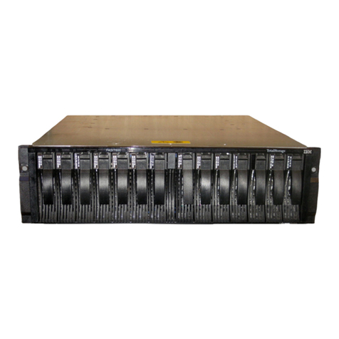
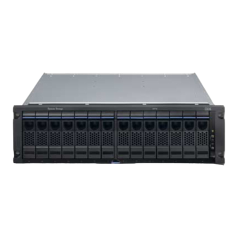
1. This figure shows 12 drives and two end caps
(model 2076-112). ...........4
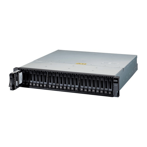
2. This figure shows 24 drives and two end caps
(model 2076-124). ...........4
3. Rear view of a model 2076-112 or a model
2076-124 control enclosure ........4
4. This figure shows the data ports in the rear of
the control enclosure...........5
5. 10 Gbps Ethernet ports on the rear of the
Storwize V7000 enclosure ........6
6. Rear view of a model 2076-212 or a model
2076-224 expansion enclosure .......6
7. SAS ports and LEDs in rear of expansion
enclosure..............7
8. Front view of file module ........8
9. Rear view of file module ........8
10. Recommended rack locations.......11
11. Securing an enclosure to a rack cabinet 14
12. Hole locations in the front of the rack....15
13. Hole locations in the back of the rack ....16
14. Removing the enclosure end cap .....17
15. Securing an enclosure to a rack cabinet 18
16. Cable management arm box contents. ....19
17. Friction rail box contents. ........20
18. Locate a 2U space in the lower section of the
rack. ...............20
19. Open the rear slide rail hooks. ......21
20. Install the rear end of the slide rails. ....21
21. Install the front end of the slide rails. ....22
22. Install the front end of the slide rails. ....22
23. Install the file module on the slide rails. 23
24. Slide the file module into the rack. .....23
25. Install the cable management support arm. It
can be installed on either side (left or right).
The graphic shows the rear of the rack. . . . 24
26. Install the cable management arm. .....24
27. Adjust the location of the cable management
arm. ...............25
28. Connect and route the cables. ......25
29. Secure the cable management arm and the file
module in the rack for shipping if needed. . . 26
30. Install the front screws. ........26
31. Internal cabling connections between file
modules (A & B), control enclosure (C), and
expansion enclosures (D & E). ......28
32. Attaching an expansion enclosure to the
control enclosure ...........29
33. Adding a second expansion enclosure....30
34. Attaching SAS cables to the enclosures 31
35. Control enclosure Ethernet network
connections. ............32
36. 10 Gbps Ethernet ports on the rear of the
Storwize V7000 enclosure ........33
37. File module node Ethernet network
connections. ............34
38. Diagram showing how to connect the file
modules to the control enclosure using Fibre
Channel cables. Refer to previous table. . . . 37
39. Unlocking the cable retention bracket ....38
40. Sliding the cable retention bracket directly
behind the power cord .........39
41. 24 drives and two end caps .......40
42. 12 drives and two end caps .......40
43. LEDs on the power supply units of the
expansion enclosure..........41
44. LEDs on the power supply units of the control
enclosure .............42
45. Here are examples of IP addresses, machine
names, and so forth. The expansion enclosures
are not shown. ...........45
46. Initialization tool welcome panel .....49
47. Here are examples of IP addresses, machine
names, and so forth. The expansion enclosures
are not shown. ...........52
© Copyright IBM Corp. 2011, 2012 v
|
||
|
||
||
||
|
||
