IBM SAN512B-6 Manual

IBM Storage Networking SAN512B-6
Installation, Service, and User Guide
MTM Service information: 8961-F08
SC27-8966-02
IBM


IBM Storage Networking SAN512B-6
Installation, Service, and User Guide
MTM Service information: 8961-F08
SC27-8966-02
IBM

Read Before Using
This product contains software that is licensed under written license agreements. Your use of such software is subject to the
license agreements under which they are provided.
Before you use the information in this publication, be sure to read the general information under “Notices” on page 251.
Copyright
Portions Copyright © 2016 Brocade Communications Systems, Inc. All Rights Reserved.
© Copyright IBM Corporation 2017.
US Government Users Restricted Rights – Use, duplication or disclosure restricted by GSA ADP Schedule Contract
with IBM Corp.

Contents
Figures .............. vii
Tables ............... ix
Read this first ............ xi
Getting help .............. xi
Accessibility features ........... xi
How to send your comments ........ xii
Safety and environmental notices ... xiii
Safety notices and labels .......... xiii
Cautions ............... xiii
Danger notices ............. xv
Safety labels ............. xviii
Attention notices ............ xx
ESD precautions............. xx
Rack safety .............. xx
Environmental notices ........... xx
About this document ........ xxi
Product documents ........... xxi
Brocade documents ........... xxi
IBM and Brocade product matrix....... xxii
Chapter 1. Introducing the SAN512B-6 . 1
Product features ............. 1
Hardware components ........... 2
Port-side view of device .......... 3
Port-side slot numbering .......... 5
Nonport-side view of the device ........ 5
Chapter 2. Preparing for the Installation 7
Safety precautions ............ 7
Facility requirements ........... 10
Time and items required for installation ..... 11
Quick installation checklists ......... 13
Items shipped ............. 15
Chapter 3. Mounting the Device .... 17
Mounting options ............ 17
Mounting precautions ........... 17
Unpacking and transporting the device ..... 19
Port-side slot numbering .......... 20
Installing the 14U Rack Mount Kit for Four-Post
Racks ................ 20
Time and items required ......... 20
Parts list .............. 21
Parts list – NEBS kit .......... 22
Assembling the rack hardware ....... 23
Installing the device in the rack....... 26
Installing the 14U Chassis Mid-Mount Rack Kit for
Two-Post Racks ............. 28
Time and Items required ......... 28
Parts list .............. 29
Assembling the rack hardware ....... 30
Installing the device in the rack....... 32
Removing the protective cover ........ 34
Chapter 4. Initial Setup and Verification 37
Configuration and verification task guide .... 37
Items required ............. 38
Providing power to the device ........ 39
Connecting power cord to AC power supplies.. 39
Connecting power cord to HVAC/HVDC power
supplies .............. 40
Establishing a serial connection to the device ... 46
Configuring the IP addresses ........ 48
Establishing an Ethernet connection to the device.. 49
Setting the domain ID ........... 50
Setting the date and time .......... 50
Setting the time zone .......... 51
Synchronizing local time with an external source 52
Customizing the chassis and switch name .... 53
Veifying the PID mode .......... 53
Verifying installed licenses and license key .... 54
Verifying correct operation ......... 54
Backing up the configuration ........ 55
Powering down the chassis ......... 56
Chapter 5. Installing Transceivers and
Cables ............... 57
Supported transceivers and cables ....... 57
Core routing blades........... 58
Time and items required .......... 60
Precautions specific to transceivers and cables ... 61
Cleaning the fiber-optic connectors ...... 61
Cable management ............ 62
Installing an SFP+ transceiver ........ 62
Replacing an SFP+ transceiver ........ 64
Installing a QSFP transceiver ........ 65
Replacing a QSFP transceiver ........ 66
Verifying the operation of new transceivers.... 68
Chapter 6. Monitoring the switch ... 69
Interpreting port blade LEDs ........ 69
Interpreting extension blade LEDs ....... 72
Interpreting control processor blade LEDs .... 74
Interpreting core routing blade LEDs ...... 77
Interpreting WWN card LEDs ........ 78
Interpreting power supply LEDs ....... 79
Interpreting fan assembly LEDs ....... 82
Interpreting POST and boot results ...... 84
POST ............... 84
Boot ................ 85
Using monitoring commands ........ 85
chassisShow ............. 86
errDump and errShow.......... 89
fanShow .............. 90
haShow............... 90
© Copyright IBM Corp. 2017 iii
||
||
|
||

historyShow ............. 91
psShow............... 92
sensorShow ............. 92
slotShow .............. 92
sfpShow .............. 93
switchShow ............. 99
supportSave ............. 100
tempShow ............. 101
Running diagnostic tests.......... 103
Chapter 7. Port and Extension Blades 105
Port blade overview ........... 105
FC32-48 blade port numbering and trunking 105
Extension blade overview ......... 107
Extension features ........... 108
SX6 blade port numbering and trunking ... 109
Precautions specific to the blade ....... 110
Faulty blade indicators .......... 111
Time and items required for removal and
installation .............. 111
Removing a blade ............ 111
Installing a blade ............ 114
Verifying blade operation ......... 115
Chapter 8. Core Routing Blades ... 117
Core routing blade overview ........ 117
CR32-8 port numbering ......... 117
ICL trunking groups .......... 119
ICL cabling configurations ........ 120
Precautions specific to the blade ....... 122
Faulty core routing blade indicators ...... 123
Time and items required.......... 124
Removing a core routing blade ....... 124
Installing a core routing blade ........ 127
Verifying blade operation ......... 128
Chapter 9. Control Processor Blades 129
Control processor blade overview ...... 129
CPX6 port identification ......... 130
Precautions specific to the blade ....... 131
Blade fault indicators........... 131
Blade replacement task guide ........ 132
Time and items required for replacement .... 133
Preparing for replacement ......... 133
Replacing a CP blade........... 134
Hot-swap procedure .......... 135
Cold-swap procedure.......... 141
Completing the replacement ....... 143
Verifying blade operation ......... 144
Chapter 10. WWN Cards....... 147
WWN card overview ........... 147
WWN card location and numbering ..... 147
Precautions specific to WWN cards ...... 148
WWN card fault indicators ......... 148
WWN card replacement task guide ...... 150
Time and items required for replacement .... 150
Using the wwnrecover utility ........ 151
Preparing for WWN card replacement ..... 152
Hot-swap replacement .......... 153
Cold-swap replacement .......... 154
Removing the WWN card and bezel...... 156
Configuring airflow direction on WWN cards .. 157
Verifying WWN card operation ....... 159
Chapter 11. Power Supply Assemblies 161
AC power supply overview ........ 161
Fan and power supply airflow ...... 162
Power supply assembly numbering ..... 163
HVAC/HVDC power supply overview.... 164
Precautions specific to power supply assembly .. 166
Power supply assembly fault indicators .... 166
Power supply assembly task guide ...... 167
Time and items required.......... 168
Removing a power supply ......... 168
Installing a power supply ......... 169
Verifying power supply operation ...... 170
Chapter 12. Fan Assemblies ..... 173
Fan assembly overview .......... 173
Fan and power supply airflow ...... 174
Fan assembly numbering ........ 176
Precautions specific to fan assemblies ..... 176
Fan assembly fault indicators ........ 177
Fan assembly task guide ......... 177
Time and items required.......... 178
Removing a fan assembly ......... 178
Installing a fan assembly ......... 179
Verifying fan operation .......... 180
Chapter 13. Blade Filler Panels .... 181
Blade filler panel removal and replacement ... 181
Removing a filler panel .......... 181
Installing a filler panel .......... 182
Chapter 14. Cable management comb 185
Cable management comb overview ...... 185
Time and items required for removal and
installation .............. 185
Removing cable management comb ...... 185
Installing cable management comb ...... 186
Chapter 15. Chassis door ...... 187
Chassis door overview .......... 187
Time and items required.......... 187
Removing a chassis door ......... 187
Installing a chassis door .......... 188
Chapter 16. Replacing the Chassis 191
Chassis replacement overview........ 191
Precautions specific to chassis replacement ... 191
Chassis replacement task guide ....... 192
Customer replacement responsibilities .... 193
IBM service replacement responsibilities ... 203
Chapter 17. Removing the battery .. 207
Appendix A. SAN rack ....... 209
Installing the IBM SAN rack ........ 209
iv SAN512B-6 Installation, Service, and User Guide
||
||
||
||
||
||
||

Step 1. Position the rack ......... 210
Step 2. Level the rack.......... 210
Step 3. Attach the stabilizers ....... 211
Step 4. Attach the rack to a concrete floor ... 212
Step 5. Attach the rack to a concrete floor
beneath a raised floor ......... 214
Step 6. Attach the mounting plates ..... 217
Step 7. Attach the front door ....... 217
Step 8. Check the customer's ac power source 218
Step 9. Check the intelligent power distribution
units ............... 219
Step 10. Connect switch and device cables... 221
Step 11. Power on the rack ........ 221
Service procedures ........... 222
Director power-off procedure ....... 222
Removing and replacing the iPDUs ..... 223
Removing and replacing the front or rear rack
door ............... 224
Relocating the rack .......... 225
Parts information ........... 226
SAN rack specifications ......... 233
Appendix B. Product specifications 235
Notices .............. 251
Trademarks .............. 252
Homologation statement ......... 252
Electronic emission notices ......... 252
Federal Communications Commission Statement 252
Industry Canada Compliance Statement ... 253
Australia and New Zealand Class A Statement 253
European Union Electromagnetic Compatibility
Directive .............. 253
Germany Electromagnetic Compatibility
Directive .............. 254
People's Republic of China Class A Statement 256
Taiwan Class A Statement ........ 256
Taiwan Contact Information ....... 256
Japan Voluntary Control Council for Interference
Class A Statement ........... 256
Japan Electronics and Information Technology
Industries Association Statement ...... 257
Korean Communications Commission Class A
Statement ............. 257
Russia Electromagnetic Interference Class A
Statement ............. 258
Index ............... 259
Contents v
||
||
||
||
|
||
||
||
||
|
||
||
||
||
||
||
|
||
||
||
||

vi SAN512B-6 Installation, Service, and User Guide

Figures
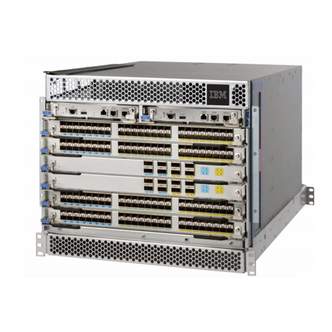
1. Port side of the SAN512B-6 (sample
configuration) ............ 4
2. Nonport side of the SAN512B-6 (sample
configuration) ............ 6
3. Rack kit parts ............ 22
4. NEBS kit parts list .......... 23
5. Left and right shelf brackets installed on rails 24
6. Nut and screw locations for mounting the
device .............. 25
7. Positioning the device for installation in a rack 27
8. Attaching port side of device to rack rails 28
9. Rack kit parts ............ 30
10. Attaching the rear tray to the rack rails 31
11. Attaching the front tray to the rack rails 32
12. Placing the device in the trays ...... 33
13. Attaching trays to the device....... 34
14. Removing protective cover from SAN512B-6 35
15. QSFP transceiver with separate cable .... 58
16. 2 km QSFP 16 Gbps with integrated cable 59
17. 2 km LWL QSFP transceiver with integrated
cable ............... 60
18. Female-to-female patch cable for QFSP
connections ............ 60
19. Optical transceiver extraction tool ..... 61
20. Installing an SFP+ transceiver with pull tab
into blade port ........... 63
21. Installing an SFP+ transceiver with bail latch
into blade port ........... 63
22. Replacing a SFP+ optical transceiver with pull
tab into blade port .......... 64
23. Installing an SFP+ transceiver with bail latch
into blade port ........... 65
24. Installing a QSFP transceiver into blade port 66
25. Installing a QSFP optical transceiver into blade
port ............... 67
26. FC32-48 port blade LEDs ........ 70
27. SX6 Extension blade LEDs ....... 72
28. Control processor blade (CPX6) ...... 75
29. CR32-8 core routing blade LEDs ..... 77
30. WWN card LEDs on bezel ....... 79
31. 2870 W AC Power supply LED ...... 79
32. Fan assembly LEDs .......... 83
33. FC32-48 blade port numbering ...... 106
34. SX6 extension blade port numbering 109
35. Removing and replacing port or extension
blade .............. 113
36. CR32-8 core routing blade port numbering 118
37. ICL cable connections (sample configuration) 121
38. Core-edge ICL topology ........ 122
39. Removing and installing a core routing blade 126
40. CPX6 blade port identification ...... 130
41. Removal and replacement of the control
processor blade (CPX6) ........ 136
42. Removal and replacement of the control
processor blade (CPX6) ........ 142
43. WWN card location and numbering .... 148
44. Removing and installing WWN cards 157
45. AC power supply assembly....... 161
46. Airflow labels ........... 162
47. Power supply assembly numbering .... 163
48. HVAC/HVDC power supply assembly 165
49. Removing and installing power supply
assembly ............. 169
50. Fan assembly ........... 174
51. Airflow labels ........... 175
52. Fan assembly numbering ....... 176
53. Removing and installing a fan assembly 179
54. Removing and installing the blade filler panel 182
55. Removing and installing the blade filler panel 183
56. Removing or installing cable management
comb .............. 186
57. Removal and replacement of the chassis door 188
58. Removing protective cover from SAN512B-6
chassis .............. 189
59. Removal and replacement of the chassis door 190
60. Location of battery holder ....... 207
61. Caster wheel ............ 210
62. Adjusting the leveling feet ....... 211
63. Stabilizers............. 211
64. Attaching the rack to a concrete floor 212
65. Leveling the rack .......... 214
66. Attaching the rack to a raised floor .... 215
67. Leveling the rack .......... 216
68. Attaching the mounting plate ...... 217
69. Attaching the front door ........ 218
70. Power cord cabling (rack side view) .... 221
71. SAN rack with iPDU locations ...... 223
72. Removing the rack door ........ 225
73. iPDU locations ........... 232
74. iPDU (PN 00FW787) for director attachment 233
© Copyright IBM Corp. 2017 vii
||
||
||
||
||
||
||
||

||
||

||
||
||
||
||

||
||
||

||
viii SAN512B-6 Installation, Service, and User Guide

Tables
1. Brocade and IBM product and model number
matrix .............. xxii
2. Facility requirements ......... 10
3. Installation tasks, time, and items required 12
4. Installation prerequisites ........ 13
5. Installation and basic system configuration 13
6. Configuration and verification tasks .... 37
7. HVAC/HVDC power cable ....... 45
8. Example: tsTimeZone command parameter
selection for the US time zones ...... 52
9. Supported transceivers and cables ..... 57
10. Port blade LED descriptions ....... 70
11. Extension blade LED descriptions ..... 73
12. CP blade LED descriptions ....... 75
13. Core routing blade LED descriptions .... 78
14. WWN card LED descriptions ...... 79
15. 2870 W AC Power supply LED descriptions 81
16. 2870 W AC Power supply LED descriptions
(continued)............. 82
17. Fan assembly LED descriptions ...... 83
18. External port to slotShow port mapping for
core blades ............ 119
19. Messages that may indicate WWN card
failure .............. 149
20. RASlog messages from WWN card audit 151
21. HVAC/HVDC power cable wiring .... 166
22. Critical information checklist ...... 195
23. Power cables for side-mount iPDUs .... 231
24. Items supplied with the 14U director chassis
mount kit ............. 231
25. IBM SAN rack specifications ...... 233
© Copyright IBM Corp. 2017 ix
||
||
||
|
||
||
xSAN512B-6 Installation, Service, and User Guide

Read this first
Summary of changes
This is the first edition of the IBM®Storage Networking SAN512B-6 Installation,
Service, and User Guide.
Getting help
For the latest version of your product documentation, visit the web at
http://www.elink.ibmlink.ibm.com/public/applications/publications/cgibin/
pbi.cgi.
For more information about IBM SAN products, see the following Web
site:http://www.ibm.com/servers/storage/san/
For support information for this product and other SAN products, see the
following Web site:http://www.ibm.com/servers/storage/support/san
For detailed information about the Fibre Channel standards, see the Fibre Channel
Industry Association (FCIA) Web site at: www.fibrechannel.org/
Visit www.ibm.com/contact for the contact information for your country or region.
You can also contact IBM within the United States at 1-800-IBMSERV
(1-800-426-7378). For support outside the United States, you can find the service
number at: http://www.ibm.com/planetwide/.
Accessibility features
Accessibility features help users who have a disability, such as restricted mobility
or limited vision, to use information technology products successfully.
Accessibility features
The following list includes the major accessibility features in this product:
vLight emitting diodes (LEDs) that flash at different rates, to represent the same
information as the colors of the LEDs
vIndustry-standard devices for ports and connectors
vManagement of the product through management applications is available
through Web and Graphical User Interface (GUI) options
Keyboard navigation
This product does not have an attached or integrated keyboard. Any keyboard
navigation is provided through the management software and GUI.
Vendor software
This product includes certain vendor software that is not covered under the IBM
license agreement. IBM makes no representation about the accessibility features of
© Copyright IBM Corp. 2017 xi

these products. Contact the vendor for the accessibility information about its
products.
Related accessibility information
You can view the publications for this product in Adobe Portable Document
Format (PDF) using the Adobe Acrobat Reader. The PDFs are provided on a
product documentation CD-ROM that is packaged with the product. The CD-ROM
also includes an accessible HTML version of this document.
IBM and accessibility
See the IBM Human Ability and Accessibility Center website at
www.ibm.com/able/ for more information about the commitment that IBM has to
accessibility.
How to send your comments
Your feedback is important in helping us provide the most accurate and
high-quality information. If you have comments or suggestions for improving this
document, you can send us comments electronically by using the following
addresses:
vInternet: [email protected]
vIBMLink from U.S.A.: STARPUBS at SJEVM5
vIBMLink from Canada: STARPUBS at TORIBM
vIBM Mail Exchange: USIB3VVD at IBMMAIL
You can also mail your comments by using the Reader Comment Form in the back
of this manual or direct your mail to:
International Business Machines Corporation
Information Development
Department GZW
9000 South Rita Road
Tucson, Arizona 85744–0001 U.S.A.
When you send information to IBM, you grant IBM a nonexclusive right to use or
distribute the information in any way it believes appropriate without incurring any
obligation to you.
xii SAN512B-6 Installation, Service, and User Guide

Safety and environmental notices
This section contains information about:
v“Safety notices and labels”
v“Rack safety” on page xx
v“Environmental notices” on page xx
Safety notices and labels
When using this product, observe the danger, caution, and attention notices
contained in this guide. The notices are accompanied by symbols that represent the
severity of the safety condition. The danger and caution notices are listed in
numerical order based on their IDs, which are displayed in parentheses, for
example (D004), at the end of each notice. Use this ID to locate the translation of
these danger and caution notices in the Safety Notices publication that is shipped
with this product.
The following notices and statements are used in IBM documents. They are listed
below in order of increasing severity of potential hazards. Follow the links for
more detailed descriptions and examples of the danger, caution, and attention
notices in the sections that follow.
vNote: These notices provide important tips, guidance, or advice.
v“Attention notices” on page xx: These notices indicate potential damage to
programs, devices, or data.
v“Cautions”: These statements indicate situations that can be potentially
hazardous to you.
v“Danger notices” on page xv: These statements indicate situations that can be
potentially lethal or extremely hazardous to you. Safety labels are also attached
directly to products to warn of these situations.
vIn addition to these notices, “Safety labels” on page xviii may be attached to the
product to warn of potential hazards.
Cautions
A Caution statement alerts you to situations that can be potentially hazardous to
you or cause damage to hardware, firmware, software, or data.
General cautions
CAUTION:
Changes or modifications made to this device that are not expressly
approved by the party responsible for compliance could void the
user's authority to operate the equipment.
CAUTION:
Disassembling any part of the power supply and fan assembly voids
the warranty and regulatory certifications. There are no
user-serviceable parts inside the power supply and fan assembly.
© Copyright IBM Corp. 2017 xiii

CAUTION:
Make sure the airflow around the front, sides, and back of the device
is not restricted.
CAUTION:
Ensure that the airflow direction of the power supply unit matches
that of the installed fan tray. The power supplies and fan trays are
clearly labeled with either a green arrow with an "E", or an orange
arrow with an "I."
CAUTION:
To protect the serial port from damage, keep the cover on the port
when not in use.
CAUTION:
Never leave tools inside the chassis.
CAUTION:
Use the screws specified in the procedure. Using longer screws can
damage the device.
CAUTION:
To avoid damaging blade and chassis, do not push the blade into a
slot or pull the blade from a slot using the ejector handles.
CAUTION:
Remove the protective cover on the port side of chassis before
applying power. This cover is attached over the air vents. If not
removed, the chassis can overheat and will eventually shut down.
Electrical cautions
CAUTION:
Use a separate branch circuit for each power cord, which provides
redundancy in case one of the circuits fails.
CAUTION:
For the NEBS-compliant installation of a device with AC or DC
systems, use a ground wire of at least 2 AWG. The ground wire
should have an agency-approved crimped connector (provided with
the device) attached to one end, with the other end attached to
building ground. The connector must be crimped with the proper tool,
allowing it to be connected to both ground screws on the enclosure.
Before crimping the ground wire into the provided ground lug, ensure
that the bare copper wire has been cleaned and antioxidant is applied
to the bare wire. In addition, anti-rotation devices or lock washers
must be used with all screw connections for the grounding wire.
xiv SAN512B-6 Installation, Service, and User Guide

CAUTION:
All devices with AC power sources are intended for installation in
restricted access areas only. A restricted access area is a location where
access can be gained only by service personnel through the use of a
special tool, lock and key, or other means of security.
CAUTION:
Before plugging a cable into any port, be sure to discharge the voltage
stored on the cable by touching the electrical contacts to ground
surface.
CAUTION:
Static electricity can damage the chassis and other electronic devices.
To avoid damage, keep static-sensitive devices in their static-protective
packages until you are ready to install them.
CAUTION:
If you do not install a module or a power supply in a slot, you must
keep the slot filler panel in place. If you run the chassis with an
uncovered slot, the system will overheat.
Cautions related to equipment weight
18-32 kg (39.7-70.5 lbs)
svc00167
CAUTION:
Do not use the port cover tabs to lift the module. They are not
designed to support the weight of the module, which can fall and be
damaged.
18-32 kg (39.7-70.5 lbs)
svc00167
CAUTION:
To prevent damage to the chassis and components, never attempt to
lift the chassis using the fan or power supply handles. These handles
were not designed to support the weight of the chassis.
Danger notices
A Danger statement indicates conditions or situations that can be potentially lethal
or extremely hazardous to you. Safety labels are also attached directly to products
to warn of these conditions or situations.
General dangers
DANGER
The procedures in this manual are for qualified service personnel.
DANGER
Be careful not to accidently insert your fingers into the fan tray
while removing it from the chassis. The fan may still be spinning
at a high speed.
Safety and environmental notices xv

DANGER
This equipment is suitable for mounting on concrete or other
noncombustible surfaces only.
Dangers related to equipment weight
18-32 kg (39.7-70.5 lbs)
svc00167
DANGER
Use safe lifting practices when moving the product.
18-32 kg (39.7-70.5 lbs)
svc00167
DANGER
Make sure the rack housing the device is adequately secured to
prevent it from becoming unstable or falling over.
18-32 kg (39.7-70.5 lbs)
svc00167
DANGER
Mount the devices you install in a rack as low as possible. Place
the heaviest device at the bottom and progressively place lighter
devices above.
18-32 kg (39.7-70.5 lbs)
svc00167
DANGER
A completely empty chassis weighs approximately 35.61 kg (78.5 lb)
and requires a hydraulic or assisted lift to install it.
18-32 kg (39.7-70.5 lbs)
svc00167
DANGER
A fully populated chassis weighs approximately 145.83 kg (321.5
lbs) and requires a hydraulic or assisted lift to install it.
xvi SAN512B-6 Installation, Service, and User Guide

18-32 kg (39.7-70.5 lbs)
svc00167
DANGER
If a lift tool with a capacity of at least 350 lbs is not available, the
director chassis must be depopulated completely before installing
it into the rack. Remove the power supplies, fan modules, all of the
blades, the cable management comb, and the chassis door (if
equipped). Install the empty chassis into the rack following the
chassis installation instructions. The weight of the empty chassis is
78.5 lbs (35.6 kg) and must be lifted by minimum 3 people. After
securing the chassis to the rack, reinstall the power supplies, fan
modules, and the blades and proceed with the installation.
Electrical dangers
DANGER
Make sure that the power source circuits are properly grounded,
then use the power cord supplied with the device to connect it to
the power source.
DANGER
Before beginning the installation, see the precautions in “Power
precautions.”
DANGER
For safety reasons, the ESD wrist strap should contain a series 1
megaohm resistor.
DANGER
If the installation requires a different power cord than the one
supplied with the device, make sure you use a power cord
displaying the mark of the safety agency that defines the
regulations for power cords in your country. The mark is your
assurance that the power cord can be used safely with the device.
DANGER
Disconnect the power cord from all power sources to completely
remove power from the device.
Safety and environmental notices xvii

DANGER
High Touch Current. Earth connection essential before connecting
supply.
Laser dangers
DANGER
All fiber-optic interfaces use Class 1 lasers.
DANGER
Use only optical transceivers that are qualified by IBM and comply
with the FDA Class 1 radiation performance requirements defined
in 21 CFR Subchapter I, and with IEC 825 and EN60825. Optical
products that do not comply with these standards might emit light
that is hazardous to the eyes.
DANGER
Laser Radiation. Do Not View Directly with Optical Instruments.
Class 1M Laser Products.
Safety labels
As an added precaution, safety labels are often installed directly on products or
product components to warn of potential hazards. These can be either danger or
caution notices, depending upon the level of the hazard.
The actual product safety labels may differ from these sample safety labels:
DANGER
Hazardous voltage, current, or energy levels are present inside
any component that has this label attached. Do not open any
cover or barrier that contains this label. (L001)
Do not service, there are no serviceable parts.
xviii SAN512B-6 Installation, Service, and User Guide
Table of contents
Other IBM Network Storage Server manuals

IBM
IBM 7979A1U User manual

IBM
IBM TotalStorage DS4300 Turbo User manual

IBM
IBM SAN256B-6 Manual

IBM
IBM TOTAL STORAGE NAS 100 Programming manual

IBM
IBM TotalStorage FAStT200 User manual

IBM
IBM TotalStorage DS4300 Turbo Operating instructions

IBM
IBM 220 Owner's manual

IBM
IBM Storwize V7000 User manual

IBM
IBM 2073-700 User manual

IBM
IBM TotalStorage FAStT600 User manual

IBM
IBM J15 User manual

IBM
IBM E10 User manual

IBM
IBM TotalStorage NAS 300 User manual

IBM
IBM Flex System 68Y8588 User manual

IBM
IBM TotalStorage FAStT600 User manual

IBM
IBM TotalStorageFAStT900 User manual

IBM
IBM 9370 User manual

IBM
IBM TotalStorage FAStT700 User manual

IBM
IBM 5147-084 User manual

IBM
IBM N3700 A20 Manual