INTRODUCTION
This service manual describes the latest technical
information for the IC-M803 MF/HF MARINE
TRANSCEIVER at the time of publication.
MODEL VERSION VERSION
NUMBER
IC-M803 USA #11
To upgrade quality, any electrical or mechanical parts and
internal circuits are subject to change without notice or
obligation.
SERVICE CAUTION
NEVER connect the transceiver to an AC outlet or
to a DC power supply that outputs more than the
specified voltage. This will ruin the transceiver.
DO NOT expose the transceiver’s main unit to rain,
snow or liquids.
DO NOT reverse the polarity of the DC power cable
when directly connecting to the transceiver.
DO NOT apply an RF signal of more than 20 dBm
(100 mW) to the antenna connector. This could
damage the transceiver’s front-end.
ORDERING PARTS
Be sure to include the following four points when
ordering replacement parts:
1. 10-digit Icom part number
2. Component name
3. Equipment model name and unit name
4. Quantity required
<ORDER EXAMPLE>
1130016460 R2A20169SA IC-M803 MAIN UNIT 5 pieces
8930102460 4100 IC CLIP IC-M803 CHASSIS 1 piece
Addresses are provided on the inside back cover for
your convenience.
REPAIR NOTES
1. Make sure that the problem is internal before
disassembling the transceiver.
2. DO NOT open the transceiver until it is
disconnected from its power source.
3. DO NOT short any circuits or electronic parts.
4. DO NOT keep power ON for a long time when the
transceiver is defective.
5. NEVER directly transmit power into any test
equipment such as Standard Signal Generator,
otherwise the RF power may damage them.
6. ALWAYS connect a 50 dB to 60 dB attenuator
between the transceiver and such test equipment.
7. READ the instructions of the test equipment
thoroughly before connecting it to the transceiver.
8. If the front panel and case of the remote controller
are separated and reassembled, waterproof
performance will not be guaranteed unless the
specified waterproof check is performed.
Icom, Icom Inc. and the Icom logo are registered trademarks of Icom Incorporated (Japan) in Japan, the United States, the
United Kingdom, Germany, France, Spain, Russia, Australia, New Zealand, and/or other countries.
REMOTE CONTROLLER
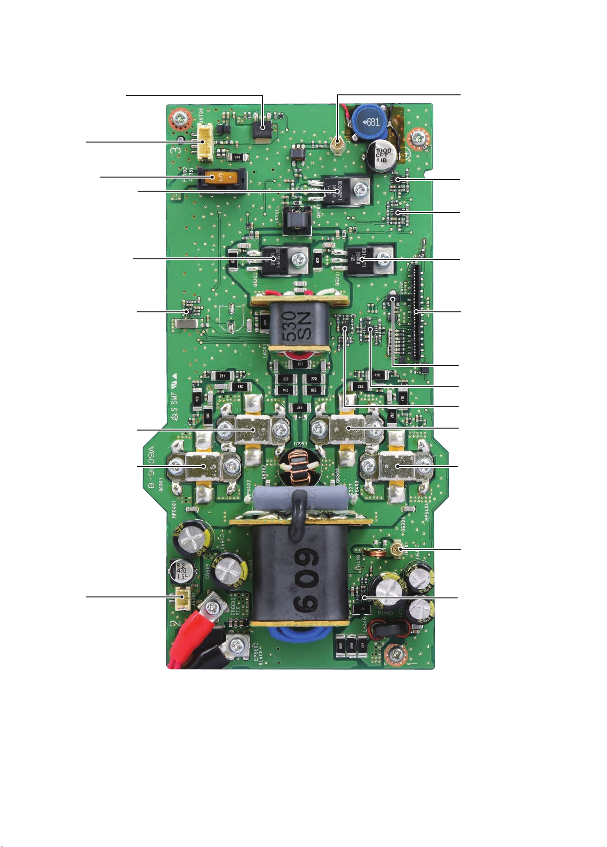
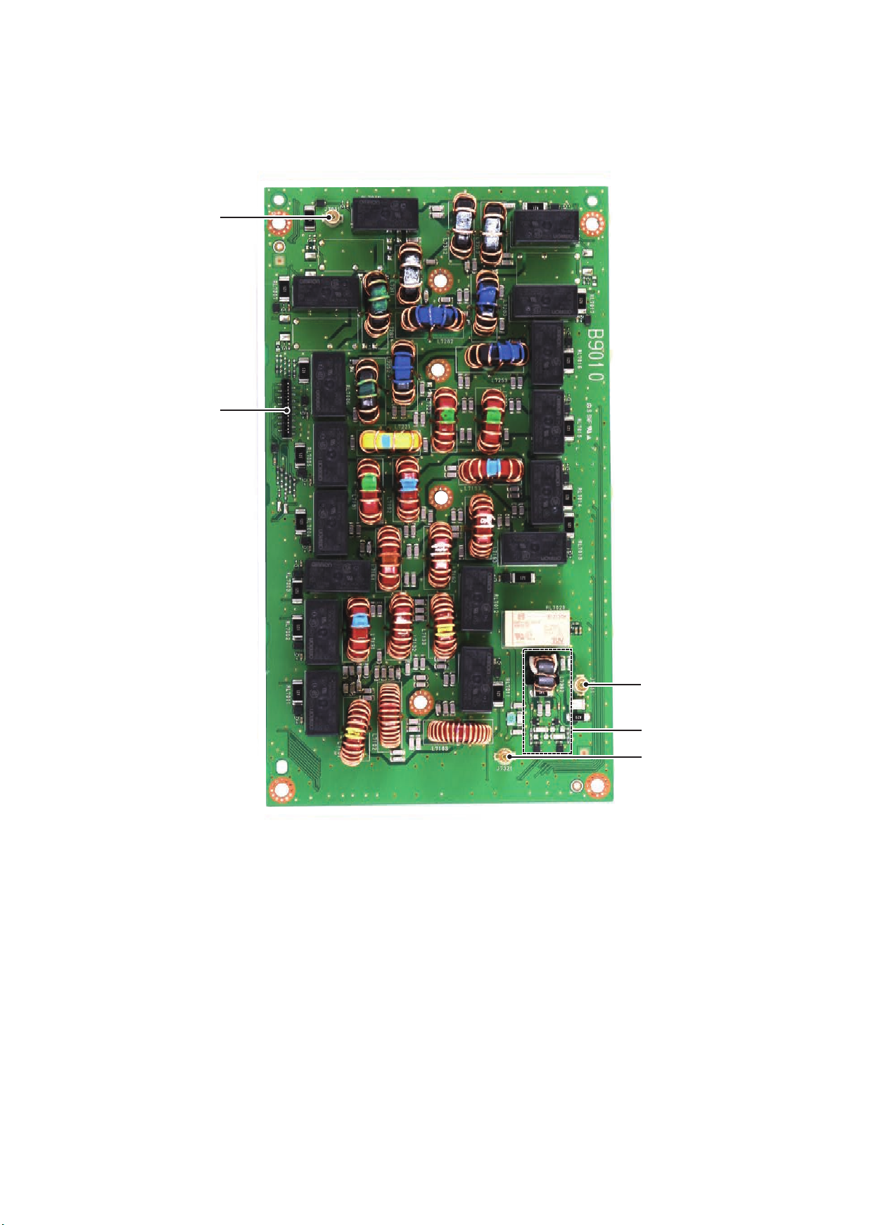
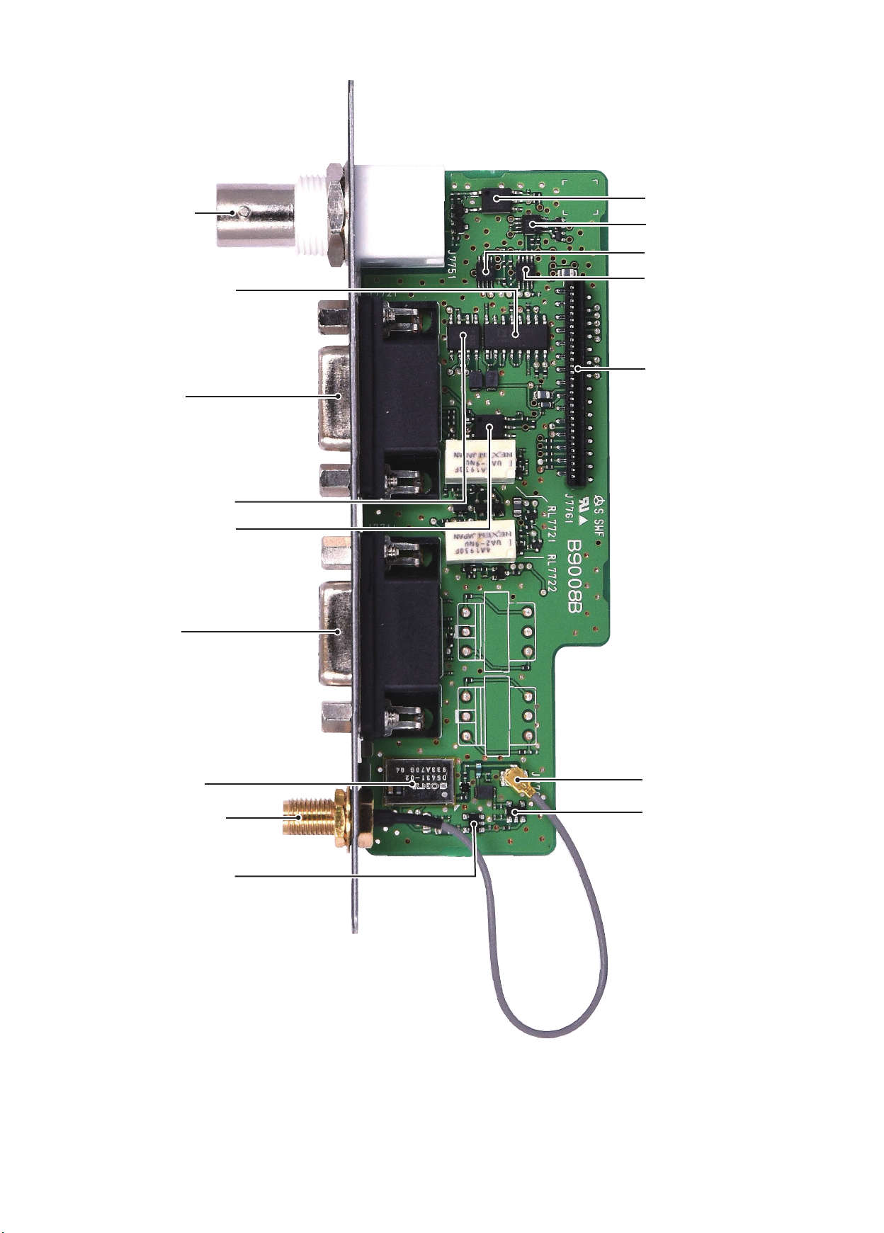
IC-M803 MAIN UNIT
IC-M803
MICROPHONE
HM-214