IDK COS-100HD-B Operating manual

HDMI Coaxial Cable Extender
COS-100HD-B
<Command Reference Guide>
Ver.1.0.0
RS-232C
L
AUDIO INPUT
R
Tx
1 COAXTxfor HDMI COS-T100HD-B
FGDC 5V 3A HDMI
OUTPUT
HDMI
INPUT
POWER
STATUS
LINK KEY LOCK
-+
SET
SIGNAL HDCP
RS-232C
FGDC 5V 3A HDMI
Rx
COS-R100HD-B
L
AUDIO OUTPUT
R
POWER
STATUS
LINK KEY LOCK
-+
SET
SIGNAL HDCP
OUTPUTINPUT
1 COAXRxfor HDMI
OUTPUT
Thank you for choosing our product.
To ensure the best performance of this product, please read this user guide fully and carefully before
using it and keep this manual together with the product for reference as needed.
IDK Corporation

COS-100HD-B Command Guide
2
Trademarks
The terms HDMI and HDMI High-Definition Multimedia Interface, and the HDMI Logo are trademarks or
registered trademarks of HDMI Licensing Administrator, Inc. in the United States and other countries.
All other company and product names mentioned in this document are either registered trademarks or
trademarks of their respective owners. In this document, the “®” or “™” marks may not be specified.

COS-100HD-B Command Guide
3
Before reading this manual
All rights reserved.
Some of the contents in this Command guide such as appearance diagrams, menu operations,
communication commands, and so on may differ depending on the version of the product.
This Command guide is subject to change without notice. You can download the latest version from IDK’s
website at: http://www.idkav.com
The reference manual consists of the following two volumes:
■User guide: Please download the user guide from the website above.
Provides explanations and procedures for operations, installation, connections among devices,
I/O adjustment and settings.
■Command guide (this document):
Provides explanations and procedures for external control using RS-232C and LAN communications.

COS-100HD-B Command Guide
4
Table of Contents
1About this Guide......................................................................................................................................... 5
2Command outline ....................................................................................................................................... 6
3“Setting mode”............................................................................................................................................ 7
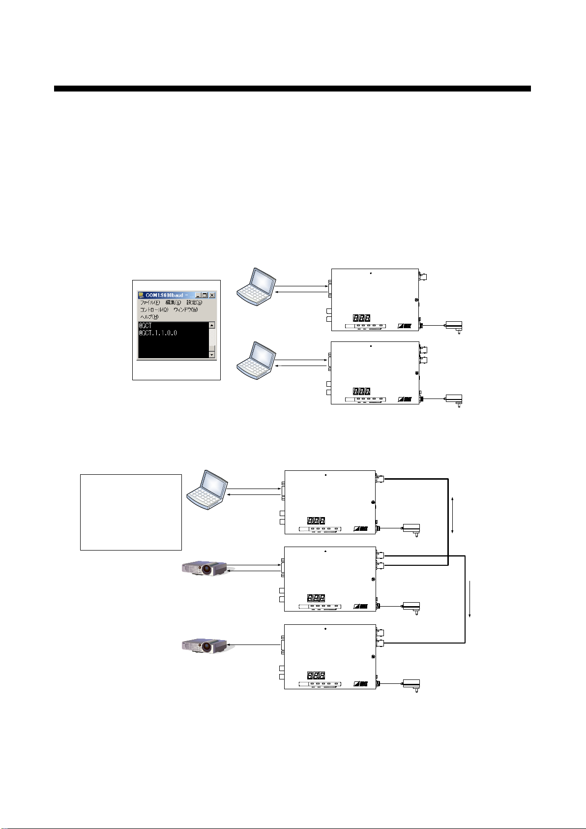
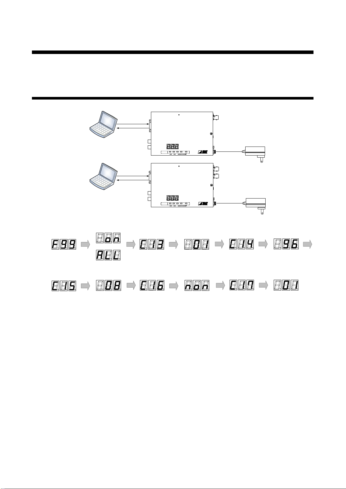
3.1 Controlling transmitter or receiver......................................................................................................... 7
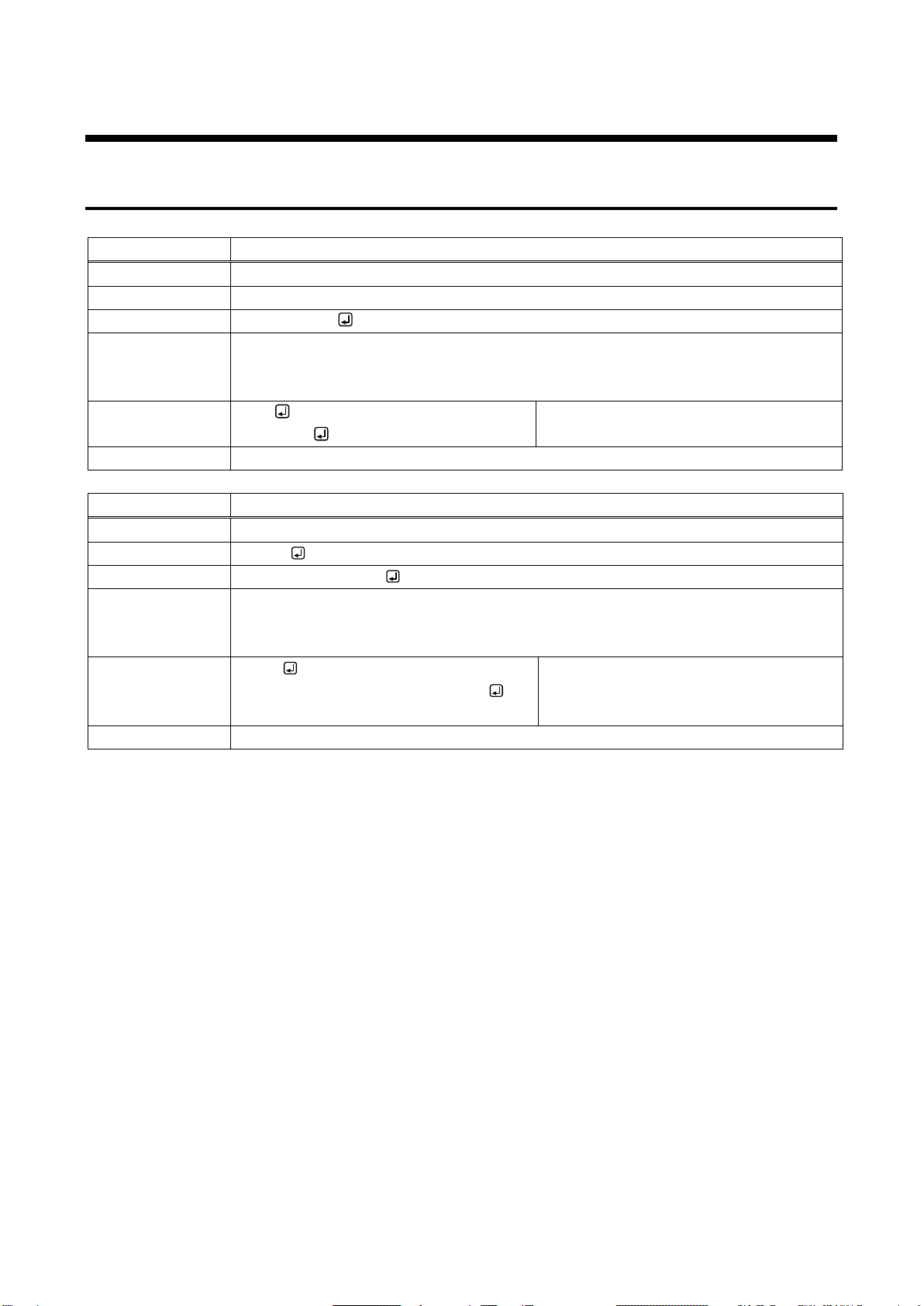
3.2 Command list........................................................................................................................................ 9
3.3 Detailed descriptions........................................................................................................................... 10
3.3.1 Command to transmitter and receiver......................................................................................... 10
3.3.2 Transmitter.................................................................................................................................. 12
3.3.3 Receiver ...................................................................................................................................... 14
4“Transmission mode”................................................................................................................................ 15
4.1 Transmitting data between transmitter and receiver .......................................................................... 15
4.2 Command list...................................................................................................................................... 17
4.3 Detailed descriptions........................................................................................................................... 17
4.3.1 Command to transmitter and receiver......................................................................................... 17
4.4 Daisy Chain connection...................................................................................................................... 18
4.5 Notes................................................................................................................................................... 21
5Connecting RS-232C ............................................................................................................................... 22
6RS-232C communication specification..................................................................................................... 23

COS-100HD-B Command Guide
5
1 About this Guide
This guide explains how to control the COS using commands through RS-232C communication and transmit
RS-232C data between TX and RX.
There are two modes
“Setting mode” : For controlling transmitter or receiver from external device
“Transmission mode” : For data communication between transmitter and receiver
The setting procedure is common to both transmitter and receiver.
Use appropriate RS-232C cable for connected devices.
【See: 5 Connecting RS-232C】
Laptop
RS-232C
cable
Laptop
RS-232C
cable
RS-232C
L
AUDIO INPUT
R
Tx
1 COAXTx for HDMI
COS-T100HD-B
FGDC 5V 3A HDMI
OUTPUT
HDMI
INPUT
POWER
STATUS
LINK KEY LO CK
-+
SET
SIGNAL HDCP
RS-232C
FGDC 5V 3A HDMI
Rx
COS-R100HD-B
L
AUDIO OUTPUT
R
POWER
STATUS
LINK KEY LO CK
-+
SET
SIGNAL HDCP
OUTPUTINPUT
1 COAXRx for HDMI
OUTPUT
External control
by communication command
<Setting mode>
[Fig. 1.1] Setting mode
Laptop
RS-232C
cable
Projector RS-232C
cable
Coaxial cable
RS-232C L
AUDIO INPUT
R
Tx
1 COAXTx for HDMI
COS-T100HD-B
FGDC 5V 3A HDMI OUTPUT
HDMI
INPUT
POWER
STATUS
LINK KEY LO CK
-+
SET
SIGNAL HDCP
RS-232C
FGDC 5V 3A HDMI
Rx
COS-R100HD-B
L
AUDIO OUTPUT
R
POWER
STATUS
LINK KEY LO CK
-+
SET
SIGNAL HDCP
OUTPUTINPUT
1 COAXRxfor HDMI
OUTPUT
Projector RS-232C
cable
RS-232C
FGDC 5V 3A HDMI
Rx
COS-R100HD-B
L
AUDIO OUTPUT
R
POWER
STATUS
LINK KEY LO CK
-+
SET
SIGNAL HDCP
OUTPUTINPUT
1 COAXRxfor HDMI
OUTPUT
Coaxial cable
Communication
data
Communication
data
<Transmission mode>
Enables:
Data communication between
transmitter and receiver
and
Bidirectional communication with
a selected receiver in Daisy
chain connection
[Fig. 1.2] Transmission mode

COS-100HD-B Command Guide
6
2 Command outline
A command consists of “@” (“40” in hexadecimal), 3 one-byte alphabetical characters (upper and lower
cases), and parameters (one-byte numbers*). For some commands, several parameters can be specified or
no parameter is required. Processing is executed by sending a delimiter at the end of the command.
Example: @S*S, 1
“,”( a comma, “2C” in hexadecimal) is indicated between a command and parameter and between two
parameters.
An error command is returned if an undefined command or wrong parameter is included.
Example:@S*S, 10
@ERR, 1
If only delimiter is sent, the command list will be returned.
Example:
--------------- HELP (1/2) ---------------
(Com Port Setting Command)
@SCT / @GCT: Set/Get RS-232C Interface
(OTHERS Command)
@GIV: Get ID & Version
@GIS: Get Input Status
------------------------------------------

COS-100HD-B Command Guide
7
3 “Setting mode”
The “Setting mode” is for controlling the transmitter or receiver from external devices using RS-232C
communication. You can set the transmitter or receiver and check the I/O status using commands.
3.1 Controlling transmitter or receiver
Laptop
Setting mode
RS-232C
Communication mode
Displayed
Maintenance menu
or
Baud rate
RS-232C communication
Baud rate
Data bit length Parity check Stop bit
RS-232C communication
Data bit length RS-232C communication
Parity check RS-232C communication
Stop bit
RS-232C
cable
Laptop
RS-232C
cable
RS-232C
L
AUDIO INPUT
R
Tx
1 COAXTxfor HDMI COS-T100HD-B
FGDC 5V 3A HDMI
OUTPUT
HDMI
INPUT
POWER
STATUS
LINK KEY L OCK
-+
SET
SIGNAL HDCP
RS-232C
FG
DC 5V 3A HDMI
Rx
COS-R100HD-B
L
AUDIO OUTPUT
R
POWER
STATUS
LINK KEY LO CK
-+
SET
SIGNAL HDCP
OUTPUT
INPUT
1 COAXRx for HDMI
OUTPUT
●“Setting mode”and RS-232C communication
[Fig. 3.1] Setting mode

COS-100HD-B Command Guide
8
■
To enable “Setting mode”
1
Place control device, transmitter or receiver, and then connect them using an RS-232C cable.
2
Power on each device.
3
Set the RS-232C communication mode of the transmitter and receiver to “Setting mode”.
*1
Set [F99] (Maintenance/Status display menu) to “on” or “ALL” (Always displayed).
Set [C13] (RS-232C communication mode) to “01” (setting mode).
4
Set the RS-232C communication settings between transmitter and receiver.
*2
Set “[C14]” (RS-232C communication baud rate) depending on the control device.
Set “[C15]” (RS-232C communication data bit) depending on the control device.
Set “[C16]” (RS-232C communication parity check) depending on the control device.
Set “[C17]” (RS-232C communication stop bit) depending on the control device.
5
Execute the desired command.
【See: 3.3 Detailed descriptions】
6
Set “[F99]” (Maintenance/Status display menu) to “oFF” (Not displayed) as needed.
*1 If the RS-232C communication settings between control device and transmitter/receiver are set correctly,
the RS-232C communication mode can be set using (@S*S) command.
【See: @S*S】
*2 If the RS-232C communication settings between control device and transmitter/receiver are set correctly,
the RS-232C communication can be set using (@SCT) command. If changing RS-232C communication
setting, change the control device setting.
【See: @SCT / @GCT】

COS-100HD-B Command Guide
9
3.2 Command list
Command to transmitter and receiver
Command Function Page
@ERR
Error status
10
@GIV
Version
10
@SCT / @GCT
RS-232C communication
11
@S*S
RS-232C communication mode
11
Transmitter
Command Function Page
@GIS Input signal status 12
@S** / @G** RS-232C communication: Destination ID 13
@S*R / @G*R RS-232C communication: Bidirectional enabled ID 13
Receiver
Command Function Page
@GOS Sink device status 14
@S*I / @G*I RS-232C communication: Receiver ID 14

COS-100HD-B Command Guide
10
3.3 Detailed descriptions
3.3.1 Command to transmitter and receiver
@ERR
Error status
Function Getting
Format Return value only
Return value
@ERR, error
Parameter error: Error status
1 = Erroneous parameter format or value
2 = Undefined command or wrong format
Example
GIV
@ERR, 2
@GIV is sent.
Command format error
Remarks -
@GIV
Version
Function Getting
Format @GIV
Return value
@GIV, id, firm, hard
Parameter
id : Model number
firm : Firmware version
hard : Hardware version
Example
@GIV
@GIV, COS-T100HD-B, 1.00, 1.00
Getting the version information
Firmware version : 1.00
Hardware version: 1.00
Remarks
-

COS-100HD-B Command Guide
11
@SCT / @GCT
RS-232C communication
Function Getting Setting
Format
@GCT
@SCT, bps, length, parity, stop
Return value @GCT, bps, length, parity, stop @SCT, bps, length, parity, stop
Parameter
bps: baud rate
0 = 4800 bps, 1 = 9600 bps [Default], 2 = 19200 bps,
3 = 38400 bps
length: Data bit length
0 = 7 bit, 1 = 8 bit [Default]
parity: Parity check
0 = NONE [Default], 1 = ODD, 2 = EVEN
stop: Stop bit
0 = 1 bit [Default], 1 = 2 bit
Example
@GCT
@GCT, 1, 1, 0, 0
Getting communication settings of
RS-232Cs
- Baud rate : 9600 [bps]
- Data bit length : 8 [bit]
- Parity check : NONE
- Stop bit : 1 [bit]
Completed
@SCT, 1, 1, 0, 0
@SCT, 1, 1, 0, 0
Setting communication settings of
RS-232Cs as follows:
- Baud rate : 9600 [bps]
- Data bit length : 8 [bit]
- Parity check : NONE
- Stop bit : 1 [bit]
Completed
Remarks If RS-232C communication setting is changed, the communication may be disabled.
Change the environmental settings based on the transmitter or receiver settings.
Common to transmission and setting modes
@S*S
RS-232C communication mode
Function
Setting
Format
@S*S, mode
Return value
@S*S, mode
Parameter
mode: RS-232C communication mode setting
0= Transmission mode [Default], 1= Setting mode
Example @S*S, 1
@S*S, 1
Setting to the RS-232C setting mode
Completed
@S*S, 0
@S*S, 0
Setting to the RS-232C transmission
mode
Completed
Remarks

COS-100HD-B Command Guide
12
3.3.2 Transmitter
@GIS
Input signal status
Function
Getting
Format
@GIS, mode
Return value
@GIS, mode, status_1 (, status_2, status_3)
Parameter mode: Getting status
0 = All statuses of input signals
1 = Input mode/Input color depth
2 = Input resolution/Input video frequency
3 = Digital audio input format/Digital audio input sampling frequency
status_1: Input mode/Input color depth
Input
mode Description Input
color
depth
Description
d DVI mode, without HDCP 08 24 bit/pixel (8 bit/component)
D DVI mode, with HDCP 10 30 bit/pixel (10 bit/component)
h HDMI mode, without
HDCP 12 36 bit/pixel (12 bit/component)
H HDMI mode, with HDCP
N No signal is input.
status_2: Input resolution/Input video frequency
Reply example
Description
1920x1080p 59.94Hz
1080p 59.94 Hz
1600x1200p 60.00Hz
UXGA 60 Hz
NO SIGNAL
No signal is input.
status_3: Digital audio input format/Digital audio input sampling frequency
Reply example
Description
L-PCM 48kHz
2-channel LPCM 48 kHz
L-PCM 48kHz M
Multi-channel LPCM 48 kHz
COMPRESSED AUDIO
Compressed audio
NO AUDIO
No audio is input. (e.g. DVI mode)
NO SIGNAL
No signal is input.
Example @GIS, 0
@GIS, 0, H08, 1920x1080p 59.94Hz,
L-PCM 48kHz
Getting all input statuses.
Input status: HDMI mode, with HDCP;
Color depth: 24 bit/pixel (8 bit/component);
Input resolution: 1080p 59.94 Hz;
Digital audio input status:
2-channel LPCM 48 kHz;
Digital audio input sampling frequency:
48 kHz
Remarks -

COS-100HD-B Command Guide
13
@S** / @G**
RS-232C communication: Destination ID
Function
Getting
Setting
Format
@G**
@S**, ID1 (, ID2,
・・・
ID15)
Return value
@G**, ID1 (, ID2,
・・・
ID15)
@S**, ID1 (, ID2,
・・・
ID15)
Parameter ID1 to ID15: Destination ID
0= To all receivers [Default]
1 to 15= To specified receivers
Example @G**
@G**, 1, 2, 3
Getting Destination IDs
“1”, “2”, and “3”
@S**, 1, 2, 3
@S**, 1, 2, 3
Setting destination ID to “1”, “2”, and “3”
Completed
Remarks 【See: RS-232C communication: Receiver ID】
@S*R / @G*R
RS-232C communication: Bidirectional enabled ID
Function Getting Setting
Format
@G*R
@S*R, ID
Return value
@G*R, ID
@S*R, ID
Parameter
ID: Bidirectional enabled ID
0 to 15= From a specified receiver [Default] 0
Example @G*R
@G*R, 0
Getting Bidirectional enabled ID
Set Bidirectional enabled ID is “0”
@S*R, 1
@S*R, 1
Setting Bidirectional enabled ID to “1”
Completed
Remarks “ID” is set to “0” by default. With the default setting, data can be received from the
receiver that is closest to the transmitter.
To transmit data to a specific receiver, set “ID” to a value other than “0”.
【See: RS-232C communication: Receiver ID】

COS-100HD-B Command Guide
14
3.3.3 Receiver
@GOS
Sink device status
Function
Getting
Format
@GOS, mode
Return value
@GOS, mode, status_1 (, status_2)
Parameter mode: Getting status
0 = All statuses of sink device, 1 = HDCP of sink device,
2 = HDCP authentication between the COS and sink device
status_1: HDCP of sink device
Reply example Description
HDCP SUPPORT Device with HDCP is connected.
HDCP NOT SUPPORT Device without HDCP is connected.
UNCONNECTED Sink device is not connected.
status_2: HDCP authentication between the COS and sink device
Reply example
Description
HDCP OFF Device with HDCP is not input or sink device
without HDCP is connected.
HDCP OK
Authentication succeeded
HDCP ERROR
Authentication failed
HDCP CHECK NOW
Being authentication processing
Example
@GOS, 0
@GOS, 0, HDCP SUPPORT, HDCP OK
Getting all statuses of sink device
Sink device with HDCP is connected and
HDCP authentication completed.
Remarks -
@S*I / @G*I
RS-232C communication: Receiver ID
Function Getting Setting
Format @G*I @S*I, ID
Return value @G*I, ID @S*I, ID
Parameter ID: Receiver ID
0 to 15 = Receiver ID [Default] 0
Example
@G*I
@G*I, 0 Getting the Receiver ID
“0”
@S*I, 0
@S*I, 0
Setting Receiver ID to “0”
Completed
Remarks “ID” is set to “0” by default. With the default setting, all receivers can receive data from
the transmitter, and data can be received only from the receiver that is closest to the
transmitter.
To transmit data to a specific receiver, set the Receiver ID to a value other than “0” and
set the Destination ID and Bidirectional enabled ID to the Receiver ID.
【See: RS-232C communication: Destination ID】
【See: RS-232C communication: Bidirectional enabled ID】

COS-100HD-B Command Guide
15
4 “Transmission mode”
The Daisy Chain connection enables simultaneous transmission to all receivers and bidirectional
communication with a specific receiver.
4.1 Transmitting data between transmitter and receiver
Laptop
RS-232C
cable
Projector RS-232C
cable
Coaxial cable
Transmission mode
RS-232C
communication mode
After setting
RS-232C communication
RS-232C L
AUDIO INPUT
R
Tx
1 COAXTx for HDMI
COS-T100HD-B
FGDC 5V 3A HDMI OUTPUT
HDMI
INPUT
POWER
STATUS
LINK KEY L OCK
-
+
SET
SIGNAL HDCP
RS-232C
FGDC 5V 3A HDMI
Rx
COS-R100HD-B
L
AUDIO OUTPUT
R
POWER
STATUS
LINK KEY L OCK
-+
SET
SIGNAL HDCP
OUTPUT
INPUT
1 COAXRx for HDMI
OUTPUT
●Setting transmission mode
[Fig. 4.1] Transmission mode

COS-100HD-B Command Guide
16
■
To enable “Transmission mode”
1
Place control device, transmitter and receiver, external device and then connect them using an
RS-232C cable.
2
Power on each device.
3
Enable “Setting mode” of the transmitter and receiver and set the RS-232C communication.
For RS-232C communication, see the “3.1 Controlling transmitter or receiver”.
4
Set the RS-232C communication mode of the transmitter and receiver to “Transmission mode”.*
Set [F99] (Maintenance/Status display menu) to “on” or “ALL” (Always displayed).
Set [C13] (RS-232C communication mode) to “00” (transmission mode).
5
Set “[F99]” (Maintenance/Status display menu) to “oFF” (Not displayed) as needed.
* If the RS-232C communication settings between control device and transmitter/receiver are set correctly,
the RS-232C communication mode can be set using (@S*S) command.
【See: @S*S】

COS-100HD-B Command Guide
17
4.2 Command list
If transmitter or receiver is set to “Transmitter mode”, only (@S*S) is available.
Command to transmitter and receiver
Command Function Page
@S*S RS-232C communication mode 17
4.3 Detailed descriptions
4.3.1 Command to transmitter and receiver
@S*S
RS-232C communication mode
Function
Setting
Format
@S*S, mode
Return value
@S*S, mode
Parameter mode: RS-232C communication mode setting
0= Transmission mode [Default], 1= Setting mode
Example @S*S, 1
@S*S, 1 Setting to the RS-232C setting mode
Completed
@S*S, 0
@S*S, 0
Setting to the RS-232C transmission
mode
Completed
Remarks

COS-100HD-B Command Guide
18
4.4 Daisy Chain connection
■
Default settings
The Destination ID, Bidirectional enabled ID, and Receiver ID are set to “0” by default.
Data can be transmitted from a transmitter to all receivers; data can be received only from the receiver that is
closest to the transmitter.
Laptop
RS-232C
cable
Projector RS-232C
cable
Coaxial cable
Projector RS-232C
cable
Coaxial cable
Projector RS-232C
cable
Coaxial cable
RS-232C
L
AUDIO INPUT
R
Tx
1 COAXTxfor HDMI
COS-T100HD-B
FGDC 5V 3A HDMI
OUTPUT
HDMI
INPUT
POWER
STATUS
LINK KEY L OCK
-+
SET
SIGNAL HDCP
RS-232C
FGDC 5V 3A HDMI
Rx
COS-R100HD-B
L
AUDIO OUTPUT
R
POWER
STATUS
LINK KEY LO CK
-+
SET
SIGNAL HDCP
OUTPUTINPUT
1 COAXRx for HDMI
OUTPUT
RS-232C
FGDC 5V 3A HDMI
Rx
COS-R100HD-B
L
AUDIO OUTPUT
R
POWER
STATUS
LINK KEY LO CK
-+
SET
SIGNAL HDCP
OUTPUTINPUT
1 COAXRx for HDMI
OUTPUT
RS-232C
FGDC 5V 3A HDMI
Rx
COS-R100HD-B
L
AUDIO OUTPUT
R
POWER
STATUS
LINK KEY LO CK
-+
SET
SIGNAL HDCP
OUTPUTINPUT
1 COAXRx for HDMI
OUTPUT
Sending command
Sending reply command
Not transmitting data
Transmitter Receivers
Simultaneous transmission to all
receivers
Receiver Transmitter
Data can be received only from the
receiver that is closest to the
transmitter
[Fig. 4.2] Daisy Chain connection (by default)
Note:
Data cannot be transmitted from multiple receivers.

COS-100HD-B Command Guide
19
■
Data transmission with specific receiver
Enable “Setting mode” of the transmitter and receiver and set Destination ID, Bidirectional enabled ID, and
Receiver ID.
【See: 3 “Setting mode】
【See: RS-232C communication: Destination ID】
【See: RS-232C communication: Bidirectional enabled ID】
【See: RS-232C communication: Receiver ID】
Application example for Daisy Chain connection
Destination ID: 2
Bidirectional enabled ID: 2
Receiver ID: 1, 2, 3 order of vicinity of transmitter
In this case, the transmitter and Receiver 2 can be communicated.
Laptop
RS-232C
cable
Projector RS-232C
cable
Coaxial cable
Projector RS-232C
cable
Coaxial cable
Projector RS-232C
cable
Coaxial cable
Receiver ID
RS-232C
Receiver ID
Set IDs of transmitter in Setting
mode
RS-232C
L
AUDIO INPUT
R
Tx
1 COAXTx for HDMI COS-T100HD-B
FGDC 5V 3A HDMI
OUTPUT
HDMI
INPUT
POWER
STATUS
LINK KEY LO CK
-+
SET
SIGNAL HDCP
RS-232C
FGDC 5V 3A HDMI
Rx
COS-R100HD-B
L
AUDIO OUTPUT
R
POWER
STATUS
LINK KEY LO CK
-+
SET
SIGNAL HDCP
OUTPUTINPUT
1 COAXRxfor HDMI
OUTPUT
RS-232C
FGDC 5V 3A HDMI
Rx
COS-R100HD-B
L
AUDIO OUTPUT
R
POWER
STATUS
LINK KEY LO CK
-+
SET
SIGNAL HDCP
OUTPUTINPUT
1 COAXRxfor HDMI
OUTPUT
RS-232C
FGDC 5V 3A HDMI
Rx
COS-R100HD-B
L
AUDIO OUTPUT
R
POWER
STATUS
LINK KEY LO CK
-+
SET
SIGNAL HDCP
OUTPUTINPUT
1 COAXRxfor HDMI
OUTPUT
●COS-R100HD-B (Receiver)
Set Receiver ID in Setting mode
Receiver ID 1
Receiver ID 2
Receiver ID 3
Not sending command
Sending reply command
Not transmitting data
Sending command
Receiver (ID 2) can communicate
with transmitter
[Fig. 4.3] Data transmission with specific receiver

COS-100HD-B Command Guide
20
■
To enable “Data transmission with specific receiver”
1
Connect a control device and the transmitter, the receiver and a peripheral device over an RS-232C
cable, respectively.
2
Power on each device.
3
Set the RS-232C communication mode of the transmitter and receiver to “Setting mode” and set the
RS-232C communication.
For RS-232C communication, see the “3.1 Controlling transmitter or receiver”
4
Set the Receiver ID. *1
Set “[C18]” (RS-232C communication Receiver ID setting) to “01 to 15”.*2
5
Set the Destination ID and Bidirectional enabled ID.
Set the Destination ID using (@S**) command from the transmitter and control device connected
RS-232C.
Set the Bidirectional enabled ID using (@S*R) command from the transmitter and control device
connected RS-232C.
6
Set the RS-232C communication mode of the transmitter and receiver to “Transmission mode”.*3
Set [F99] (Maintenance/Status display menu) to “on” or “ALL” (Always displayed).
Set [C13] (RS-232C communication mode) to “00” (transmission mode).
7
Set “[F99]” (Maintenance/Status display menu) to “oFF” (Not displayed) as needed.
*1 If the RS-232C communication settings between control device and transmitter/receiver are set correctly,
the Receiver ID can be set using (@S*I) command.
【See: @S*I / @G*I】
*2 Receiver ID “0” cannot be used. Set all Receiver IDs to values other than “0”.
If the same Receiver ID is set to multiple receivers, data can be sent from the transmitter to all specified
receiver. Data can be received only from the receiver that is closest to the transmitter.
*3 If the RS-232C communication settings between control device and transmitter/receiver are set correctly,
the RS-232C communication mode can be set using (@S*S) command.
【See: @S*S】
Other manuals for COS-100HD-B
1
Table of contents
Other IDK Extender manuals