IDK OPF-TH2000 User manual

4K-compatible HDMI Fiber Optic Extender
OPF-TH2000/OPF-RH2000
User’s Guide Ver.1.0.0
OPTICALRxfor HDMI OPF-RH2000
DC 5V 3A FG
OUTPUT
HDMI
RS-232C
Rx
CLASS1 LASERPRODUCT
クラス 1 レーザ製品
OPTICAL
TXSIGNAL RX
POWER
LAN
STATUS
DIP-SW
OPTICALTxfor HDMI OPF-TH2000
DC 5V 3A FG
INPUT
HDMI
RS-232C
Tx
CLASS1 LASERPRODUCT
クラス 1 レーザ製品
OPTICAL
TXSIGNAL RX
POWER
LAN
STATUS
DIP-SW
●Thank you for choosing our product.
●To ensure the best performance of this product, please read this User’s Guide fully and carefully before
using it and keep this manual beside the product.
IDK Corporation

OPF-TH2000/OPF-RH2000 User’s Guide
2
Trademarks
●The terms HDMI and HDMI High-Definition Multimedia Interface, and the HDMI Logo are trademarks or
registered trademarks of HDMI Licensing, LLC in the United States and other countries.
●All other company and product names mentioned in this manual are either registered trademarks or
trademarks of their respective owners. In this manual, the “®” or “™” marks may not be specified.

OPF-TH2000/OPF-RH2000 User’s Guide
3
Before reading this manual
All rights reserved.
Some of the contents in this User’s Guide such as appearance diagrams, menu operations,
communication commands, and so on may differ depending on the version of the extender.
This User’s Guide is subject to change without notice. You can download the latest version from IDK’s
website at: http: //www.idk.co.jp/en/index.html
FCC STATEMENT
This equipment has been tested and found to comply with the limits for a Class A digital device, pursuant to
part 15 of the FCC Rules. These limits are designed to provide reasonable protection against harmful
interference when the equipment is operated in a commercial environment. This equipment generates, uses,
and can radiate radio frequency energy and, if not installed and used in accordance with the instruction
manual, may cause harmful interference to radio communications. Operation of this equipment in a residential
area is likely to cause harmful interference, in which case the user will be required to correct the interference
at his own expense.
CE MARKING
This equipment complies with the essential requirements of the relevant European health, safety and
environmental protection legislation.
WEEE MARKING
Waste Electrical and Electronic Equipment (WEEE), Directive 2002/96/EC (This directive is
only valid in the EU.).
This equipment complies with the WEEE Directive (2002/96/EC) marking requirement.
The left marking indicates that you must not discard this electrical/electronic equipment in
domestic household waste.
The lasers in this product meet Class 1 Laser Safety per FDA/CDRH and
EN (IEC) 60825 laser safety standards which specify design safety.
クラス 1 レーザ製品
CLASS 1 LASER PRODUCT

OPF-TH2000/OPF-RH2000 User’s Guide
4
Safety instructions
Read and understand all safety and operating instructions before using this product. Follow all instructions
and cautions as detailed in this document.
Enforcement Symbol
Description
Indicates the presence of a hazard that may result in death or serious
personal injury if the warning is ignored or the equipment is handled
incorrectly.
Indicates the presence of a hazard that may cause minor personal
injury or property damage if the caution is ignored or the equipment is
handled incorrectly.
Symbol
Description
Example
Caution
This symbol is indicated to alert the user. (Warning and caution)
Electrical
Hazard
Prohibition
This symbol is intended to prohibit the user from actions.
Do not
disassemble
Instruction
This symbol is intended to instruct the user.
Unplug
Caution
Warning

OPF-TH2000/OPF-RH2000 User’s Guide
5
Prohibition
Do not place the product in any unstable place.
Install the product to a horizontal and stable place. Otherwise, it may fall/turn over and lead to injury.
Do not place the product in any environment with vibration.
Otherwise, it may move/fall and lead to injury.
Keep out any foreign objects.
In order to avoid fire or electric shock, do not allow foreign objects, such as metal and paper, to enter the product
from the vent holes.
For power cable/ plug:
Do not scratch, heat, or modify, including extending them.
Do not pull, put heavy stuff on them, or pinch them.
Do not bend, twist, or tie them together forcefully.
If they are used in those states continuously, it may cause fire or electric shock. If power cables/plugs become
damaged, contact IDK.
Do not
disassemble
Do not repair, modify or disassemble.
Since the product includes high-voltage parts, those actions may cause fire or electric shock. For internal
inspections or repairs, contact IDK.
Do not touch
In the event of lighting or thunder, do not touch the main unit or cables such as
power cable and LAN cable.
Contact may cause electric shock
Instruction
For installation:
The product is intended to be installed by skilled technicians. For installation, please contact a system integrator or
IDK. Otherwise, it may cause fire, electric shock, injury, or property damage.
Set the power plug in a convenient place to unplug easily.
You can easily unplug in case of any extraordinary failure or abnormal situation, and it also helps for unplugging
when you do not use it for a long period.
Plug the power plug into appropriate outlet completely.
If the plug is plugged incompletely, it may overheat which causes electrical shock or fire. Do not use damaged
plug or loosened outlet.
Clean the power plug regularly.
If the plug is covered in dust, it may cause fire due to reduced insulating power.
Unplug
Unplug immediately if the product smokes, makes unusual noise, or smells.
If you continue to use the product under those situations, it may cause electric shock or fire. After confirming that
the product stops smoking, contact IDK.
Unplug immediately if you drop the product or if the cabinet is damaged.
If you continue to use the product under those situations, it may cause electrical shock or fire. For maintenance
and repair, contact IDK.
Unplug immediately if water or other objects are directed inside.
If you continue to use it under those situations, it may cause electrical shock or fire. For maintenance and repair,
contact IDK.
For connection
Instruction
Differences in ground potential among the product and peripheral devices may cause electric shock or damage of
the devices. When using cables to connect devices, including connection of long-distance transmission, unplug
the power cables of all related devices.
After connecting signal/control cables of each device, plug in the power cables of each device.
Warning

OPF-TH2000/OPF-RH2000 User’s Guide
6
For installation
For rack mount devices:
Instruction
Mount the product to the rack meeting EIA standards, and maintain spaces above and
below for air cooling. For your safety, attach an L-shape bracket in addition to the mount
bracket kit for the front panel in order to balance the weight.
For devices with rubber feet:
Instruction
Never insert only the screws into the holes after removing the rubber feet. It may lead to
damage when the screws contact electrical circuit or parts inside of the product.
To put the rubber feet back on, use only provided rubber feet and screws.
Altitude:
Instruction
Do not place the product at elevations of 2,000 meters (6562 feet) or higher above sea
level. Failure to do so may shorten the life of the internal parts and result in malfunctions.
Prohibition
Do not place the product in any place where it will be subjected to high
temperatures.
If the product is subjected to direct sunlight or high temperatures, it may cause fire.
Do not place the product in humid, oil smoke, or dusty place.
If the product is placed near humidifiers or dusty area, it may cause fire or electric shock.
Do not block the vent holes.
If ventilation slots are blocked, it may cause fire or failure due to internal heat.
Do not put heavy items on the product.
It may fall/turn over and lead to injury.
Do not exceed ratings of outlet and wiring devices.
If several plugs are put in an outlet, it may cause fire and electric shock.
Use only the provided AC adapter and power cable.
If non-compliant adapter or power cables is used, it may cause fire or electrical shock. Use the provided AC
power connection cable. If you want to use your product in other countries that use different AC power cables,
contact IDK.
No wet hands
Do not plug or unplug with wet hands.
It may cause electrical shock.
Instruction
Use and store the product within the specified temperature/humidity range.
If the product is used outside the range continuously, it may cause fire or electric shock.
Turn off devices when they are connected to another device.
It may cause fire or electric shock.
Unplug
Unplug the power plug if you do not use the product for a long period.
In case of defect, it may cause fire.
Unplug the power plug before cleaning.
It may cause electric shock.
Caution

OPF-TH2000/OPF-RH2000 User’s Guide
7
Table of Contents
1Included items............................................................................................................................................ 8
2Product outline........................................................................................................................................... 9
3Features................................................................................................................................................... 10
4Part names and descriptions ................................................................................................................... 11
4.1 Transmitter.......................................................................................................................................... 11
4.2 Receiver.............................................................................................................................................. 12
5Connection............................................................................................................................................... 13
5.1 Preparation ......................................................................................................................................... 13
5.2 Precautions......................................................................................................................................... 15
5.2.1 Installation................................................................................................................................... 15
5.2.2 Cabling........................................................................................................................................ 15
5.2.3 Fiber optic cable.......................................................................................................................... 16
5.2.4SFP module................................................................................................................................. 16
5.2.5 Cascade connection.................................................................................................................... 17
5.3 Settings............................................................................................................................................... 17
5.3.1 Setting DIP switch....................................................................................................................... 17
5.3.2 Setting input equalizer (only transmitter) .................................................................................... 18
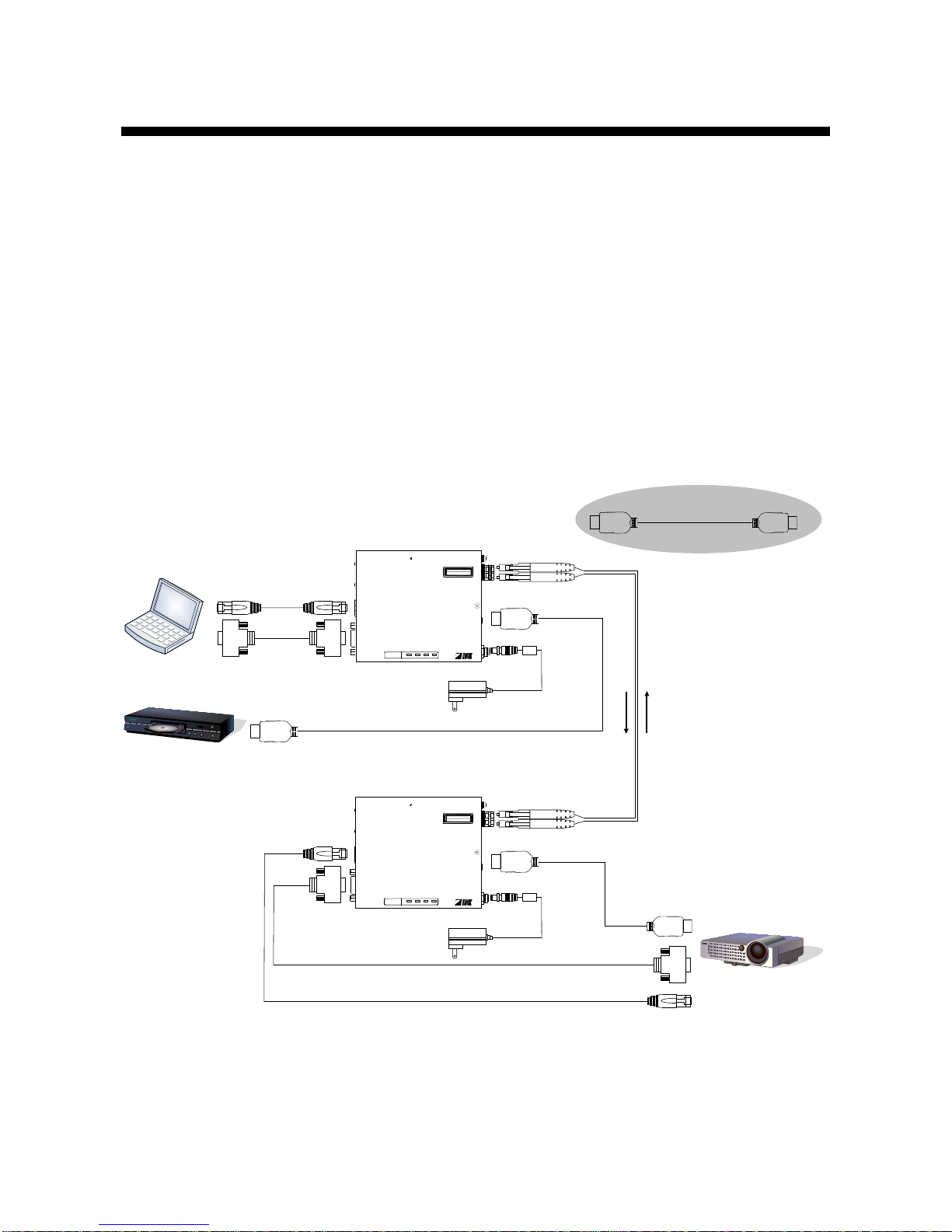
5.4 Typical application example................................................................................................................ 19
6Specification............................................................................................................................................. 20
6.1 Pin assignments.................................................................................................................................. 20
6.1.1 HDMI Type A connector.............................................................................................................. 20
6.1.2 RJ-45 connector.......................................................................................................................... 21
6.1.3 RS-232C connector..................................................................................................................... 22
6.2 Product specification........................................................................................................................... 23
7Troubleshooting ....................................................................................................................................... 25

OPF-TH2000/OPF-RH2000 User’s Guide
8
1 Included items
Make sure all items below are included in the package.
If any items are missing or damaged, please contact IDK.
“OPF-H2000”mentioned in this manual refers to OPF-TH2000 and OPF-H2000 set.
■Transmitter (OPF-TH2000)
●OPF-TH2000 (main unit) x 1
●AC adapter with screw type lock (1.2 m/3.94 feet) x 1
●Cable clamp x 1
■Receiver (OPF-RH2000)
●OPF-RH2000 (main unit) x 1
●AC adapter with screw type lock (1.2 m/3.94 feet) x 1
●Cable clamp x 1
This User’s Guide is common to both the transmitter and receiver.
You can download the latest version from IDK’s website at: http: //www.idk.co.jp/en/index.html
OPTICALTxfor HDMI OPF-TH2000
DC 5V 3A FG
INPUT
HDMI
RS-232C
Tx
CLASS1 LASERPRO DUCT
クラス 1 レーザ製品
OPTICAL
TXSIGNAL RX
POWER
LAN
STATUS
DIP-SW
OPF-TH2000
OPTICALRx for HDMI OPF-RH2000
DC 5V 3A FG
OUTPUT
HDMI
RS-232C
Rx
CLASS1 LASERPRODUCT
クラス 1 レーザ製品
OPTICAL
TXSIGNAL RX
POWER
LAN
STATUS
DIP-SW
OPF-RH2000
AC adapter with screw type lock
(1.2 m/3.94 feet)
Cable clamp

OPF-TH2000/OPF-RH2000 User’s Guide
9
2 Product outline
Caution: The OPF-H2000 outputs continuous invisible light, which may be harmful to your eyes. Please
follow the cautions below.
●Do not look into the rear panel fiber optic cable connectors or into the fiber optic cables
themselves.
●Plug the attached dust caps into the optical transceivers when the fiber optic cable is unplugged.
The OPF-H2000 is a transmitter and receiver set that enables HDMI signals to be transmitted long distance
over fiber optic cables.
The supported resolution can be up to 4K@30 or 4K@60 (4:2:0), the input signals are transmitted without
quality deterioration since they are not compressed or processed.
The OPF supports RS-232C bidirectional communication and LAN transmission.
■For multi-mode fiber
●Transmitter: OPF-TH2000-MM
●Receiver: OPF-RH2000-MM
■For single-mode fiber
●Transmitter: OPF-TH2000-SM
●Receiver: OPF-RH2000-SM
The SPF module can be replaced
depending on the fiber optic cable.
●OPF-TH2000-MM
Multimode fiber
●OPF-TH2000-SM
Singlemode fiber
●OPF-RH2000-MM
Multimode fiber
●OPF-RH2000-SM
Singlemode fiber
[Transmittter]
[Receiver]
OPTICALRxfor HDMI OPF-RH2000
DC 5V 3A FG
OUTPUT
HDMI
RS-232C
Rx
CLASS1 LASERPRODUCT
クラス 1 レーザ製品
OPTICAL
TXSIGNAL RX
POWER
LAN
STATUS
DIP-SW
OPTICALTxfor HDMI OPF-TH2000
DC 5V 3A FG
INPUT
HDMI
RS-232C
Tx
CLASS1 LASERPRODUCT
クラス 1 レーザ製品
OPTICAL
TXSIGNAL RX
POWER
LAN
STATUS
DIP-SW
OPF-H2000 series

OPF-TH2000/OPF-RH2000 User’s Guide
10
3 Features
■Video
●Maximum resolution: 4K@30 or 4K@60 (4:2:0)
●HDCP1.4 (Pass through)
●Transmission distance
Multimode fiber (OM3) : 150 m/492.13 feet
Singlemode fiber (OS1) : 1.4 km/ 0.87 mile
■Communication
●RS-232C bidirectional communication
●LAN transmission
■Others
●CEC (Pass through)
●The jack of the AC adapter has a locking mechanism.
Projector
Blu-ray disk player
Laptop
HDMI
OPF-TH2000 (Transmitter)
OPF-RH2000 (Receiver)
LAN
RS-232C
LAN
RS-232C
HDMI
HDCP output
HDCP output
Fiber optic cable
Up to 5 m/16.4 ft.
HDMI cable
OPTICAL Txfor HDMI OPF-TH2000
DC 5V 3A FG
INPUT
HDMI
RS-232C
Tx
CLASS1 LASERPRO DUCT
クラス 1 レーザ製品
OPTICAL
TXSIGNAL RX
POWER
LAN
STATUS
DIP-SW
OPTICAL Rxfor HDMI OPF-RH2000
DC 5V 3A FG
OUTPUT
HDMI
RS-232C
Rx
CLASS1 LASERPRO DUCT
クラス 1 レーザ製品
OPTICAL
TXSIGNAL RX
POWER
LAN
STATUS
DIP-SW
Typical application

OPF-TH2000/OPF-RH2000 User’s Guide
11
4 Part names and descriptions
4.1 Transmitter
①
②
③
⑧
④
⑦
⑤
⑨
⑩
⑪
⑥
OPTICALTxfor HDMI OPF-TH2000
DC 5V 3A FG
INPUT
HDMI
RS-232C
Tx
CLASS 1 LASERPRODUCT
クラス 1 レーザ製品
OPTICAL
TXSIGNAL RXPOWER
LAN
STATUS
DIP-SW
Panel drawing (Transmitter)
#
Part name
Description
①
LAN port
Port for LAN signals
②
RS-232C port
Port for RS-232C signals
③
LED lights
POWER: Lights when power is supplied from the AC adapter.
SIGNAL: Lights when video signals are valid.
TX: Lights when a valid code is sent from the OPF.
RX: Lights when a valid code is received from the fiber optic
cable connected to the receiver.
④
FG
Frame ground. An M3 screw is used.
⑤
Optical input connector
for extension
Input connector of digital optical signals for extension.
Connected to the optical output connector of receiver using a fiber optic
cable.
⑥
Optical output connector
for extension
Output connector of digital optical signals for extension.
Connected to the optical input connector of receiver using a fiber optic
cable.
⑦
HDMI cable fixing hole
Hole for the attached cable clamp to secure an HDMI cable.
⑧
HDMI input connector
Input connector for HDMI signals
Connect to a source device such as Blu-ray player.
⑨
DIP switch
Sets the +5V Power transmission of the transmitter.
【See:5.3.1】
⑩
AC adapter connector
Connector for the attached AC adapter.
⑪
Rotary switch
Sets input equalizer.
【See:5.3.2】

OPF-TH2000/OPF-RH2000 User’s Guide
12
4.2 Receiver
①
②
③
⑧
④
⑦
⑤
⑨
⑩
⑥
OPTICALRxfor HDMI OPF-RH2000
DC 5V 3A FG
OUTPUT
HDMI
RS-232C
Rx
CLASS 1 LASERPRODUCT
クラス 1 レーザ製品
OPTICAL
TXSIGNAL RXPOWER
LAN
STATUS
DIP-SW
Panel drawing (Receiver)
#
Part name
Description
①
LAN port
Port for LAN signals
②
RS-232C port
Port for RS-232C signals
③
LED lights
POWER: Lights when power is supplied from the AC adapter.
SIGNAL: Lights when video signals are valid.
TX: Lights when a valid code is sent from the OPF.
RX: Lights when a valid code is received from the fiber optic
cable connected to the transmitter.
④
FG
Frame ground. An M3 screw is used.
⑤
Optical input connector
for extension
Input connector of digital optical signals for extension.
Connected to the optical output connector of the transmitter using a fiber
optic cable.
⑥
Optical output
connector for extension
Output connector of digital optical signals for extension.
Connected to the optical input connector of the transmitter using a fiber
optic cable.
⑦
HDMI cable fixing hole
Hole for the attached cable clamp to secure an HDMI cable.
⑧
HDMI output connector
Output connector for HDMI signals
Connect to a sink device such as monitor.
⑨
DIP switch
Sets the following items: pre-emphasis and swing of TMDS signals in
the receiver, transmission response time of Hot Plug Detect, and clock
speed of Display. Data Channel signals.
【See:5.3.1】
⑩
AC adapter connector
Connector for the attached AC adapter.

OPF-TH2000/OPF-RH2000 User’s Guide
13
5 Connection
5.1 Preparation
Before connecting to external devices, such as source devices and sink devices, prepare the following cables:
●HDMI cable (Type A (19 pin) plug, 5 m/16.4 ft. or shorter)
●Fiber optic cable (2 cores, LC connector)
●LAN cable (RJ-45 connector)
●RS-232C cable (D-sub9 pin, female)
■HDMI Cable
If the external device has a DVI connector, use a proper cable.
Followings are recommended cables from IDK.
Model number
Length
HDSS-005
0.5 m/1.64 ft.
HDSS-01
1 m/3.28 ft.
HDSS-02
2 m/6.56 ft.
HDSS-03
3 m/9.84 ft.
HDSS-05
5 m/16.4 ft.
HDMI cable (flexible model)
[HDMI-DVI conversion cables]
Model number
Length
HDSS-DMHM-005
0.5 m/1.64 ft.
HDSS-DMHM-01
1 m/3.28 ft.
HDSS-DMHM-02
2 m/6.56 ft.
HDMI-DVI conversion cable (flexible model)
Model number
Length
CBL-DH-015A
1.5 m/4.92 ft.
CBL-DH-03A
3 m/9.84 ft.
CBL-DH-05A
5 m/16.4 ft.
HDMI-DVI conversion cable (standard model)

OPF-TH2000/OPF-RH2000 User’s Guide
14
■Fiber optic cable
●Use a duplex fiber cable having LC connectors for both ends.
●Use a cable whose length complies with the extension standard.
【See:5.2.3】
●IDK can provide high-performance optic cable.
[High-performance optic cable]
Part number
Part number
Part number
S-13085-2-DLC-DLC-S-LXX
S-13085-2-LC-LC-S-LXX
S-13086-2-DLC-DLC-LXX
S-13085-2-DLC-DLC-U-LXX
S-13085-2-LC-LC-U-LXX
S-13086-2-LC-LC-LXX
XX: the length (e.g. L10 = 10 m/32.8 ft.)
■LAN cable
●1G bps Ethernet signals can be transmitted over a long distance.
●Use cables meeting 10Base-T/100Base-TX/1000Base-T specification.
【See: 6.1.2】
■RS-232C cable
●RS-232C signals (up to 115.2 Kbps) can be transmitted in duplex over a long distance.
●Use a cross cable or straight cable according to the connected devices.
【See:6.1.3】

OPF-TH2000/OPF-RH2000 User’s Guide
15
5.2 Precautions
Read and follow the precautions below before connecting to external devices.
5.2.1 Installation
●Before connecting a cable to the OPF or to an external device that is connected to the OPF,
eliminate static electricity by touching metallic item or the like.
●Do not place the transmitter on top of the receiver and vice versa.
●Do not block vent holes.
Keep enough space (3 cm/1.18 inches or more) around the product.
●Do not install the OPF-H2000 in closed space.
If you have to install the product to an EIA rack mount in closed space, add a ventilation to keep
the ambient temperature of 40 degrees C/104 degrees F or less. (Exception: Installing to IDK’s
Quarter rack, RM-42HQ) If inadequately vented, the life of parts may be shortened and operations
may be affected.
Bad example
Good example
Good example
3 cm/1.18 inches or more
Space needed for OPF-H2000
5.2.2 Cabling
●Read the instruction manuals of the external devices carefully.
●Turn off the OPF-H2000 before connecting cables.
●Secure the HDMI cable using an attached cable clamp in order to prevent it from falling off this
device.
Attaching cable clamp
Fixing hole
①②③④⑤

OPF-TH2000/OPF-RH2000 User’s Guide
16
5.2.3 Fiber optic cable
To ensure the best performance of a fiber optic cable for a long-haul transmission, select and connect the
proper fiber optic cable correctly.
●Connect a fiber optic cable to the OPF as follows:
Optical output connector of the transmitter & optical input connector of the receiver
Optical input connector of the transmitter & optical output connector of the receiver
●To polish connectors:
For SFP+ module for multi-mode: PC polishing is recommended.
For SFP+ module for single-mode: UPC polishing is recommended.
Note: APC polishing is not supported.
●Extension distance varies depending on attenuation of the fiber, connector and other contact portions.
●Do not exceed the allowable tension and bend radius; otherwise it may affect the performance of the
product and the product life cycle.
●Make sure to plug the dust cap to the both ends except for when connecting it to the product. Do not leave
a fiber optic cable without the dust cap if you do not use the cable in order to prevent scratches and dirt.
●Before connecting a fiber optic cable to the OPF, make sure there is no scratch or dirt on the ends of the
connector; otherwise, the OPF may not work correctly. Clean it up if it is dirty.
Left: without dust cap
Right: with dust cap Before cleaning After cleaning
5.2.4 SFP module
The fiber type and extension distance to be used vary depending on the SFP module.
* Some SFP modules for single-mode can extend the transmission distance up to 10 km with OS1.
Please contact us if needed.
Notes:
●Plug the dust cap to the fiber optical cable if you do not use it.
●Do not use the SFP module for other devices. Do not connect the fiber optic cable that is connected to
other devices to the SFP module; otherwise, the SFP module may be broken.
●If you need to replace the SFP module, please contact us.
Multimode fiber
Singlemode fiber
Wave length
850 nm (Oxide VCSEL laser*)
1310 nm (Fabry-Perot laser*)
Maximum extension
distance
OM3: 300 m/984.25 feet
OM4: 1 km/3280.84 feet
OS1: 4.7 km/15419.94 feet
Input level
-11.2 dBm or higher
-13.8 dBm or higher
Output level
-8.2 dBm to -2 dBm
-10.6 dBm to +0.5 dBm
Optical overload
0 dBm
+0.5 dBm
Connector
LC (Duplex)

OPF-TH2000/OPF-RH2000 User’s Guide
17
5.2.5 Cascade connection
Distribution amplifiers and multi switchers that are HDCP compliant repeaters can be connected. However,
cascade connection is not available in the following cases:
●Repeater that only supports HDCP pass through (such as some switchers, boosters and so on) is
included
●Another set of OPF-TH/RH2000 (IDK’s fiber optic cable extender supporting HDCP signals)
5.3 Settings
Setting the DIP switch and input equalizer
5.3.1 Setting DIP switch
You can change the settings of the following items of the transmitter and receiver.
Transmitter : +5V power transmission method.
Receiver : Pre-emphasis and swing of TMDS signals, transmission response time of Hot Plug Detect,
and clock speed of Display. Data Channel signals.
Default: OFF (SW1 to SW4)
DIP switch
For transmitter:
DIP SW #
Function
1
+5V Power (pin18 HDMI connector): sets a transmission method.
OFF: The receiver will supply + 5V Power when + 5V Power signal was
detected by the transmitter.
ON : The receiver will supply +5V when the link between transmitter and
receiver was established, regardless of +5V that was input to the
transmitter or not.
2
Not used
3
Not used
4
Not used
For receiver:
DIP SW #
Function
1
Sets pre-emphasis of the TMDS signals.
OFF: Equalizes up to 2.5 dB.
ON : No equalization.
2
Sets the swing of the TMDS signals.
OFF: 13% amplification.
ON : No amplification.
3
Sets the response time of Hot Plug Detect transmission (pin19 HDMI connector).

OPF-TH2000/OPF-RH2000 User’s Guide
18
OFF: Transmits the detection when the Hot Plug Detect signals of the sink
device continue to change for 0.1 second or longer.
ON : Transmits the detection when the Hot Plug Detect signals of the sink
device continue to change for 1 second or longer (for 0.9 second or
shorter, it is not transmitted).
4
Sets the clock speed of the Display. Data Channel (15 pin HDMI connector) signals.
OFF: Signals are output at 100 KHz from the receiver.
ON : Signals are output at 75KHz from the receiver.
5.3.2 Setting input equalizer (only transmitter)
The HDMI signal input part has manual compensation circuit. Signal deterioration caused by cables can be
minimized by setting the amount of equalization according to the connected cable.
Default: 8
Setting input equalizer
Switch
Equalizer
0
Minimum
〜
8
(Default)
〜
F
Maximum

OPF-TH2000/OPF-RH2000 User’s Guide
19
5.4 Typical application example
Digital video and audio are transmitted from the Blu-ray disc player to the transmitter. The transmitter sends
those signals to the receiver over a fiber optic cable. The receiver outputs the received video and audio
signals to the projector from the HDMI output connector.
Peripheral device control (such as projectors) and Ethernet communication will be available by using a control
device (such as PCs).
Note: The OPF-TH2000 must be paired with OPF-RH2000. The OPF-H2000 cannot be connected to an I/O
slot board of the FDX series or other models of the OPF series.
Projector
Blu-ray player
Laptop
HDMI
OPF-TH2000 (Transmitter)
OPF-RH2000 (Receiver)
LAN
RS-232C
LAN
RS-232C
HDMI
HDCP output
HDCP output
Fiber optic cable
Up to 5 m/16.4 ft.
HDMI cable
OPTICAL Txfor HDMI OPF-TH2000
DC 5V 3A FG
INPUT
HDMI
RS-232C
Tx
CLASS1 LASERPRO DUCT
クラス 1 レーザ製品
OPTICAL
TXSIGNAL RX
POWER
LAN
STATUS
DIP-SW
OPTICAL Rxfor HDMI OPF-RH2000
DC 5V 3A FG
OUTPUT
HDMI
RS-232C
Rx
CLASS1 LASERPRO DUCT
クラス 1 レーザ製品
OPTICAL
TXSIGNAL RX
POWER
LAN
STATUS
DIP-SW
Source and sink devices are connected

OPF-TH2000/OPF-RH2000 User’s Guide
20
6 Specification
6.1 Pin assignments
6.1.1 HDMI Type A connector
Pin #
Signal name
Pin #
Signal name
1
TMDS data 2+
10
TMDS clock+
2
TMDS data 2 shield
11
TMDS clock shield
3
TMDS data 2-
12
TMDS clock-
4
TMDS data 1+
13
CEC
5
TMDS data 1 shield
14
spare (N.C.*)
6
TMDS data 1-
15
SCL
7
TMDS data 0+
16
SDA
8
TMDS data 0 shield
17
DDC/CEC ground
9
TMDS data 0-
18
+5 power supply
19
Hot plug Detect
*N.C.: No Connection
HDMI Type A assignments
1
2
19
18
Other manuals for OPF-TH2000
1
This manual suits for next models
1
Table of contents
Other IDK Extender manuals

IDK
IDK NJR-TW01UHD User manual

IDK
IDK HDC-TH100 User manual

IDK
IDK OPF-TH1000-A User manual

IDK
IDK COS-100HD-B Operating manual

IDK
IDK OPF-TH1000D User manual

IDK
IDK OPF-TH1000-A User manual

IDK
IDK HDC-UHD Series User manual

IDK
IDK COS-100HD-B User manual

IDK
IDK NJR-R04HD User manual

IDK
IDK HDC-TH100-D User manual