IDK OPF-TH1000D User manual

HDMI Fiber Optic Extender (Daisy chain model)
OPF-TH1000D / OPF-RH1000D
User’s Guide Ver.1.0.0
RS-232C
FG DC 5V 3A
L
AUDIO OUTPUT
R
POW ER
STA TUS
HDCP
HDM I INPUT
Tx
O PTIC AL DAISYCH AIN Tx for HDM I
OPF-TH1000D
RX
OPTICAL
TX
C LASS 1 LASER PRO D U C T
クラス 1 レーザ製品
KE Y LOCK
-+
SET
SIGNAL
RS-232C
FG DC 5V 3A
POW ER
STA TUS
HDCP
HDMI OUTPUT
Rx
O PTIC AL DAISYCH AIN Rx for HDM I
OPF-RH1000D
RX
OPTICAL
TX
SIGNAL
DIP SW
C LASS 1 LASER PRO D U C T
クラス 1 レーザ製品
•Thank you for choosing this IDK product.
•To ensure the best performance of this product, please read this User’s Guide fully and carefully before
using it and keep this manual beside this product.
IDK Corporation

OPF-TH1000D/OPF-RH1000D User’s Guide
2
Trademarks
The terms HDMI and HDMI High-Definition Multimedia Interface, and the HDMI Logo are trademarks or
registered trademarks of HDMI Licensing, LLC in the United States and other countries.
All other company and product names mentioned in this manual are either registered trademarks or
trademarks of their respective owners. In this manual, the “®” or “™” marks may not be specified.

OPF-TH1000D/OPF-RH1000D User’s Guide
3
Before reading this manual
•All rights reserved.
•Some of the contents in this User’s Guide such as appearance diagrams, menu operations,
communication commands, and so on may differ depending on the version of the extender.
•This User’s Guide is subject to change without notice. You can download the latest version from IDK’s
website at: http: //www.idk.co.jp/en/index.html
FCC STATEMENT
This equipment has been tested and found to comply with the limits for a Class A digital device, pursuant to
part 15 of the FCC Rules. These limits are designed to provide reasonable protection against harmful
interference when the equipment is operated in a commercial environment. This equipment generates, uses,
and can radiate radio frequency energy and, if not installed and used in accordance with the instruction
manual, may cause harmful interference to radio communications. Operation of this equipment in a residential
area is likely to cause harmful interference, in which case the user will be required to correct the interference
at his own expense.
CE MARKING
This equipment complies with the essential requirements of the relevant European health, safety and
environmental protection legislation.
WEEE MARKING
Waste Electrical and Electronic Equipment (WEEE), Directive 2002/96/EC
(This directive is only valid in the EU.)
This equipment complies with the WEEE Directive (2002/96/EC) marking requirement.
The left marking indicates that you must not discard this electrical/electronic equipment in
domestic household waste.
The lasers in this product meet Class 1 Laser Safety per FDA/CDRH and
EN (IEC) 60825 laser safety standards which specifies design safety.
クラス 1 レーザ製品
CLASS 1 LASER PRODUCT

OPF-TH1000D/OPF-RH1000D User’s Guide
4
Safety instructions
Read and understand all safety and operating instructions before using this product. Follow all instructions
and cautions as detailed in this document.
Enforcement Symbol
Description
Indicates the presence of a hazard that may result in death or serious
personal injury if the warning is ignored or the equipment is handled
incorrectly.
Indicates the presence of a hazard that may cause minor personal
injury or property damage if the caution is ignored or the equipment is
handled incorrectly.
Symbol
Description
Example
Caution
This symbol is indicated to alert the user. (Warning and caution)
Electrical
Hazard
Prohibition
This symbol is intended to prohibit the user from actions.
Do not
disassemble
Instruction
This symbol is intended to instruct the user.
Unplug
Caution
Warning

OPF-TH1000D/OPF-RH1000D User’s Guide
5
Prohibition
Do not place the product in any unstable place.
Install the product to a horizontal and stable place. Otherwise, it may fall/turn over and lead to injury.
Do not place the product in any environment with vibration.
Otherwise, it may move/fall and lead to injury.
Keep out any foreign objects.
In order to avoid fire or electric shock, do not allow foreign objects, such as metal and paper, to enter the product
from the vent holes.
For power cable/ plug:
●Do not scratch, heat, or modify, including extending them.
●Do not pull, put heavy stuff on them, or pinch them.
●Do not bend, twist, or tie them together forcefully.
If they are used in those states continuously, it may cause fire or electric shock. If power cables/plugs become
damaged, contact IDK.
Do not
disassemble
Do not repair, modify or disassemble.
Since the product includes high-voltage parts, those actions may cause fire or electric shock. For internal
inspections or repairs, contact IDK.
Do not touch
In the event of lighting or thunder, do not touch the main unit or cables such as
power cable and LAN cable.
Contact may cause electric shock
Instruction
For installation:
The product is intended to be installed by skilled technicians. For installation, please contact a system integrator or
IDK. Otherwise, it may cause fire, electric shock, injury, or property damage.
Set the power plug in a convenient place to unplug easily.
You can easily unplug in case of any extraordinary failure or abnormal situation, and it also helps for unplugging
when you do not use it for a long period.
Plug the power plug into appropriate outlet completely.
If the plug is plugged incompletely, it may overheat which causes electrical shock or fire. Do not use damaged
plug or loosened outlet.
Clean the power plug regularly.
If the plug is covered in dust, it may cause fire due to reduced insulating power.
Unplug
Unplug immediately if the product smokes, makes unusual noise, or smells.
If you continue to use the product under those situations, it may cause electric shock or fire. After confirming that
the product stops smoking, contact IDK.
Unplug immediately if you drop the product or if the cabinet is damaged.
If you continue to use the product under those situations, it may cause electrical shock or fire. For maintenance
and repair, contact IDK.
Unplug immediately if water or other objects are directed inside.
If you continue to use it under those situations, it may cause electrical shock or fire. For maintenance and repair,
contact IDK.
For connection
Instruction
Differences in ground potential among the product and peripheral devices may cause electric shock or damage of
the devices. When using cables to connect devices, including connection of long-distance transmission, unplug
the power cables of all related devices.
After connecting signal/control cables of each device, plug in the power cables of each device.
Warning

OPF-TH1000D/OPF-RH1000D User’s Guide
6
For installation
For rack mount devices:
Instruction
Mount the product to the rack meeting EIA standards, and maintain spaces above and
below for air cooling. For your safety, attach an L-shape bracket in addition to the mount
bracket kit for the front panel in order to balance the weight.
For devices with rubber feet:
Instruction
Never insert only the screws into the holes after removing the rubber feet. It may lead to
damage when the screws contact electrical circuit or parts inside of the product.
To put the rubber feet back on, use only provided rubber feet and screws.
Prohibition
Do not place the product in any place where it will be subjected to high
temperatures.
If the product is subjected to direct sunlight or high temperatures, it may cause fire.
Do not place the product in humid, oil smoke, or dusty place.
If the product is placed near humidifiers or dusty area, it may cause fire or electric shock.
Do not block the vent holes.
If ventilation slots are blocked, it may cause fire or failure due to internal heat.
Do not put heavy items on the product.
It may fall/turn over and lead to injury.
Do not exceed ratings of outlet and wiring devices.
If several plugs are put in an outlet, it may cause fire and electric shock.
Use only the provided AC adapter and power cable.
If non-compliant adapter or power cables is used, it may cause fire or electrical shock. Use the provided AC
power connection cable. If you want to use your product in other countries that use different AC power cables,
contact IDK.
No wet hands
Do not plug or unplug with wet hands.
It may cause electrical shock.
Instruction
Use and store the product within the specified temperature/humidity range.
If the product is used outside the range continuously, it may cause fire or electric shock.
Turn off devices when they are connected to another device.
It may cause fire or electric shock.
Unplug
Unplug the power plug if you do not use the product for a long period.
In case of defect, it may cause fire.
Unplug the power plug before cleaning.
It may cause electric shock.
Caution

OPF-TH1000D/OPF-RH1000D User’s Guide
7
Altitude:
Instruction
Do not place the product at elevations of 2,000 meters (6562 feet) or higher above sea
level. Failure to do so may shorten the life of the internal parts and result in malfunctions.
Table of Contants
1Included items............................................................................................................................................ 9
2Product outline......................................................................................................................................... 10
3Features................................................................................................................................................... 11
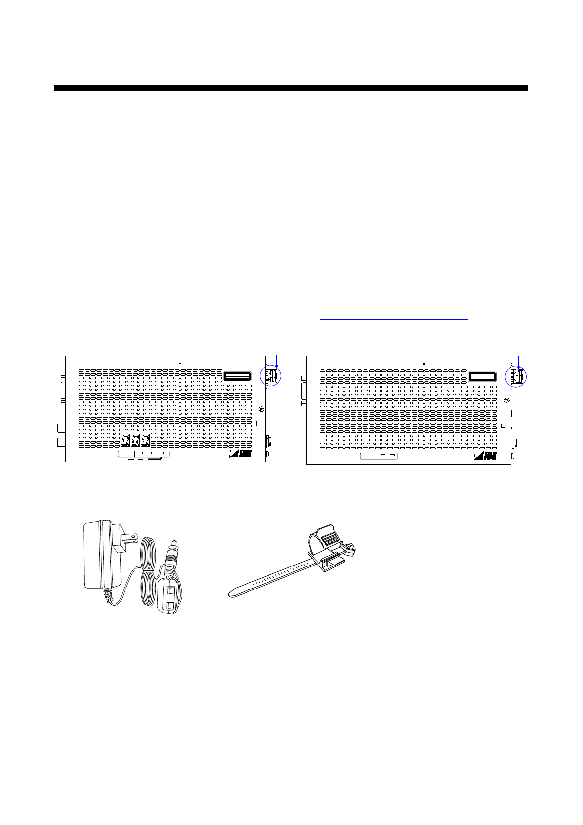
4Part names and descriptions ................................................................................................................... 12
4.1 Transmitter.......................................................................................................................................... 12
4.2 Receiver.............................................................................................................................................. 14
5Connection............................................................................................................................................... 16
5.1 Preparation ......................................................................................................................................... 16
5.2 Precautions......................................................................................................................................... 17
5.3 Application example............................................................................................................................ 19
6Basic operation ........................................................................................................................................ 20
6.1 Menu operation buttons...................................................................................................................... 20
6.2 Locking menu operation buttons......................................................................................................... 21
6.3 Initialization ......................................................................................................................................... 21
6.4 Setting transmitter and receiver using setting mode .......................................................................... 22
6.4.1 Setting transmitter....................................................................................................................... 23
6.4.2 Setting receiver ........................................................................................................................... 24
7Menus ...................................................................................................................................................... 25
7.1 Menu list.............................................................................................................................................. 25
7.2 Setting input and output (Setting menu)............................................................................................. 27
7.2.1 [F10] EDID resolution.................................................................................................................. 27
7.2.2 [F16] No-signal input monitoring time ......................................................................................... 29
7.2.3 [F22] PCM Audio......................................................................................................................... 30
7.2.4 [F24] AC-3 Dolby Digital Audio ................................................................................................... 30
7.2.5 [F26] AAC Audio ......................................................................................................................... 30
7.2.6 [F28] Dolby Digital Plus Audio..................................................................................................... 31
7.2.7 [F30] DTS Audio.......................................................................................................................... 31
7.2.8 [F32] DTS-HD Audio ................................................................................................................... 31
7.2.9 [F34] Dolby TrueHD Audio.......................................................................................................... 32
7.2.10 [F36] Audio channel .................................................................................................................... 32
7.2.11 [F65] Audio output....................................................................................................................... 33
7.2.12 [F76] EDID WXGA ...................................................................................................................... 33
7.2.13 [F90] Version............................................................................................................................... 33
7.2.14 [F99] Maintenance/status display menu ..................................................................................... 33
7.3 Verifying operation (Maintenance menu)............................................................................................ 34
7.3.1 [C06] HDCP input setting............................................................................................................ 34
7.3.2 [C55] Forced color conversion output......................................................................................... 35
7.3.3 [C90] RS-232C communication mode ........................................................................................ 35
7.4 Displaying I/O status (status display menu) ....................................................................................... 36
7.4.1 [L01 to L13] Displaying information about input.......................................................................... 36
7.4.2 [L50] Displaying information about output................................................................................... 39

OPF-TH1000D/OPF-RH1000D User’s Guide
8
8Command................................................................................................................................................. 40
8.1 Command outline................................................................................................................................ 40
8.2 Command list...................................................................................................................................... 40
8.3 Command description......................................................................................................................... 41
8.3.1 Error status.................................................................................................................................. 41
8.3.2 Setting command........................................................................................................................ 42
8.3.3 Status acquisition command....................................................................................................... 43
9Specification............................................................................................................................................. 45
9.1 Pin assignments.................................................................................................................................. 45
9.1.1 HDMI Type A connector.............................................................................................................. 45
9.1.2 RS-232C connector..................................................................................................................... 45
9.2 Product specification........................................................................................................................... 47
9.2.1 OPF-H1000D............................................................................................................................... 47
9.2.2 Standard SFP.............................................................................................................................. 49
10 Troubleshooting ....................................................................................................................................... 50

OPF-TH1000D/OPF-RH1000D User’s Guide
9
1 Included items
Make sure all items below are included in the package.
If any items are missing or damaged, please contact IDK.
“OPF-H1000D” mentioned in this manual refers to OPF-TH1000D and OPF-RH1000D set.
■Transmitter (OPF-TH1000D)
●OPF-TH1000D (main unit)x 1
●AC adapter with screw type lock (1.2 m/3.94 feet)x 1
●Cable clamp x 1
■Receiver (OPF-RH1000D)
●OPF-RH1000D (main unit)x 1
●AC adapter with screw type lock (1.2 m/3.94 feet)x 1
●Cable clamp x 1
This User’s Guide is common to both the transmitter and receiver.
You can download the latest version from IDK’s website at: http: //www.idk.co.jp/en/index.html
OPF-TH1000D
OPF-RH1000D
AC adapter with screw type lock
(1.2 m/3.94 feet)
Cable clamp
RS-232C
FG DC 5V 3A
L
AUDIO OUTPUT
R
POWER
STATUS
HDCP
HDMI INPUT
Tx
OPTICAL DAISYCHAIN Tx for HDMI
OPF-TH1000D
RX
OPTICAL
TX
CLASS 1 LASER PRODUCT
クラス 1 レーザ製品
KEY LOCK
-
+
SET
SIGNAL
Dust cap is
attached
RS-232C
FG DC 5V 3A
POWER
STATUS
HDCP
HDMI OUTPUT
Rx
OPTICAL DAISYCHAIN Rx for HDMI
OPF-RH1000D
RX
OPTICAL
TX
SIGNAL
DIP SW
CLASS 1 LASER PRODUCT
クラス 1 レーザ製品
Dust cap is
attached

OPF-TH1000D/OPF-RH1000D User’s Guide
10
2 Product outline
Caution: The OPF-H1000D outputs continuous invisible light, which may be harmful to your eyes. Please
follow the cautions below.
●Do not look into the rear panel fiber optic cable connectors or into the fiber optic cables
themselves.
●Plug the attached dust caps into the optical transceivers when the fiber cable is unplugged.
The OPF-H1000D is a transmitter and receiver set that enables HDMI signals to be transmitted long distance
over fiber optical cables. It also supports Daisy Chain.
■For multimode fiber
●Transmitter: OPF-TH1000D-MM
●Receiver: OPF-RH1000D-MM
■For singlemode fiber
●Transmitter: OPF-TH1000D-SM
●Receiver: OPF-RH1000D-SM
RS-232C
FG DC 5V 3A
L
AUDIO OUTPUT
R
POWER
STATUS
HDCP
HDMI INPUT
Tx
OPTICAL DAISYCHAIN Tx for HDMI
OPF-TH1000D
RX
OPTICAL
TX
CLASS 1 LASER PRODUCT
クラス 1 レーザ製品
KEY LOCK
-+
SET
SIGNAL
RS-232C
FG DC 5V 3A
POWER
STATUS
HDCP
HDMI OUTPUT
Rx
OPTICAL DAISYCHAIN Rx for HDMI
OPF-RH1000D
RX
OPTICAL
TX
SIGNAL
DIP SW
CLASS 1 LASER PRODUCT
クラス 1 レーザ製品
The SPF module can be replaced
depending on the fiber optic cable.
●OPF-TH1000D-MM
Multimode fiber
●OPF-TH1000D-SM
Singlemode fiber
●OPF-RH1000D-MM
Multimode fiber
●OPF-RH1000D-SM
Singlemode fiber
[Transmitter]
[Receiver]
OPF-H1000D series

OPF-TH1000D/OPF-RH1000D User’s Guide
11
3 Features
Input signals are transmitted without quality deterioration since they are not compressed or processed.
The OPF-H1000D also supports RS-232C serial one-way communication, and the transmitter outputs HDMI
embedded audio as analog audio.
■Video
●Maximum resolution: WUXGA (RB)*/1080p
●Daisy Chain connection
●Extension distance of each SFP module
Multimode fiber (OM3): 300 m/984.25 feet
Multimode fiber (OM4): 1 km/3280.84 feet
Singlemode fiber (OS1): 4.7 km/15419.95 feet
Only RB (Reduced Blanking) is supported
■Audio
●Analog audio output from HDMI embedded audio (transmitter)
■Control input
●One-way communication
■Others
●HDCP supported
●The jack of the AC adapter have a locking mechanism.
Projector
LCD monitor
Speaker
Blu-ray disc player
Amplifier
RS-232C
FG DC 5V 3A
L
AUDIO OUTPUT
R
POWER
STATUS HDCP
HDMI INPUT
Tx
OPTICAL DAISYCHAIN Tx for HDMI
OPF-TH1000D
RX
OPTICAL
TX
CLASS 1 LASER PRODUCT
クラス 1 レーザ製品
KEY LOCK
-+
SET
SIGNAL
RS-232C
FG DC 5V 3A
POWER
STATUS HDCP
HDMI OUTPUT
Rx
OPTICAL DAISYCHAIN Rx for HDMI
OPF-RH1000D
RX
OPTICAL
TX
SIGNAL
DIP SW
CLASS 1 LASER PRODUCT
クラス 1 レーザ製品
RS-232C
FG DC 5V 3A
POWER
STATUS HDCP
HDMI OUTPUT
Rx
OPTICAL DAISYCHAIN Rx for HDMI
OPF-RH1000D
RX
OPTICAL
TX
SIGNAL
DIP SW
CLASS 1 LASER PRODUCT
クラス 1 レーザ製品
Up to 5m/16.4 ft.
Laptop
Typical application (Daisy connection)

OPF-TH1000D/OPF-RH1000D User’s Guide
12
4 Part names and descriptions
4.1 Transmitter
RS-232C
FG DC 5V 3A
L
AUDIO OUTPUT
R
POWER
STATUS
HDCP
HDMI INPUT
Tx
OPTICAL DAISYCHAIN Tx for HDMI OPF-TH1000D
RX
OPTICAL
TX
CLASS 1 LASER PRODUCT
クラス 1 レーザ製品
KEY LOCK
-+
SET
SIGNAL
①
②
⑩
⑪
③
⑤
⑧
⑫
④
⑦
⑥
⑨
⑬
Panel drawing (Transmitter)
# Part name Description
①RS-232C port Port for RS-232C signals (only input)
②Audio output connector Outputs HDMI input audio as analog audio. For amplifiers, speakers, and
mixers.
③Output connector for
extension Output connector of digital optical signals for extension. Connected to the
receiver using a fiber optic cable.
④
LED for checking
transmitted or received
Lights in green when valid code is transmitted (TX) or received (RX).
⑤HDMI input connector Input connector for HDMI signals
Connect a source device such as Blu-ray players.
⑥
HDMI cable fixing hole
Hole for the attached cable clamp to secure an HDMI cable.
⑦SIGNAL LED Lights in green when vertical synchronous signals are input from the
HDMI input connector.
⑧AC adapter connector Connector for the attached AC adapter.
⑨FG Frame ground

OPF-TH1000D/OPF-RH1000D User’s Guide
13
#
Part name
Description
⑩
Menu operation
buttons
Sets I/O settings of the transmitter and locks menu operation buttons
●Use “SET”, “+”, and “-” buttons to set I/O settings of the transmitter.
●Press and hold the “SET” button in order to lock those buttons.
⑪
Segment display
Displays menu items and setting status.
⑫LED lights (green) ■POWER:
When power is supplied from the AC adapter, it lights.
■HDCP
HDCP status of input video signals from the source device.
●Lights: Video signals are input (with HDCP)
●Blinks: Video signals are input (without HDCP)
●Turned off: No video signals
■KEY LOCK
The menu operation buttons are locked or released.
●Lights: Locked
●Blinks: Being set
●Turned off: Unlocked
⑬Connector for
maintenance
Please do not use this connector.

OPF-TH1000D/OPF-RH1000D User’s Guide
14
4.2 Receiver
RS-232C
FG DC 5V 3A
POWER
STATUS HDCP
HDMI OUTPUT
Rx
OPTICAL DAISYCHAIN Rx for HDMI OPF-RH1000D
RX
OPTICAL
TX
SIGNAL
DIP SW
CLASS 1 LASER PRODUCT
クラス 1 レーザ製品
①
②
④
⑦
③
⑤
⑧
⑥
⑨
⑩
⑪
Panel drawing (Receiver)
# Part name Description
①RS-232C port Port for RS-232C signals (only output)
②DIP Switches Sets the receiver.
1. Setting RS-232C communication mode
OFF: Communication mode [Default]
ON: Setting mode (9600 bps)
2. Setting audio output
OFF: Output [Default]
ON: Not output
③I/O connector for
extension I/O connector of digital optical signals for extension. Connected to the
transmitter using a fiber optic cable.
Connected to another receiver for Daisy Chain connection.
④LED for checking
transmitted or received
Lights in green when valid code is transmitted (Tx) or received (Rx).
⑤HDMI output connector Output connector for HDMI signals. Connected to a sink device, such as
LCD monitors.
⑥
HDMI cable fixing hole
Hole for the attached cable clamp to secure an HDMI cable.

OPF-TH1000D/OPF-RH1000D User’s Guide
15
# Part name Description
⑦SIGNAL LED Lights in green when vertical synchronous signals are input from the I/O
connector for extension.
⑧AC adapter connector Connector for the attached AC adapter.
⑨FG Frame ground
⑩LED lights (green) ■POWER
When power is supplied from the AC adapter, it lights.
■HDCP
HDCP status of input video signals from the transmitter.
●Lights: Video signals are input (with HDCP)
●Blinks: Video signals are input (without HDCP)
●Turned off: No video signals
⑪Connector for
maintenance Please do not use this connector.

OPF-TH1000D/OPF-RH1000D User’s Guide
16
5 Connection
5.1 Preparation
Before connecting to external devices, such as source devices and sink devices, prepare the following cables:
●HDMI cable (Type A (19 pin) plug, 5 m/16.4 ft. or shorter)
●Fiber optic cable (LC connector)
●Stereo cable (RCA pin plug)
●RS-232C cable (D-sub9 pin, female)
■Fiber optic cable
●Use a simplex fiber cable having LC connectors for both ends.
●Use a cable whose length complies with the extension standard.
■RS-232C cable
●RS-232C signals (up to 115.2 Kbps) can be transmitted in simplex over a long distance.
●Use a cross cable or straight cable according to the connected devices.
【See 9.1.2 RS-232C】

OPF-TH1000D/OPF-RH1000D User’s Guide
17
5.2 Precautions
Read and follow the precautions below before connecting to external devices.
■Installation
●Do not place the transmitter on top of the receiver and vice versa.
●Do not block vent holes. Keep enough space (3 cm/1.18 inches or more) around the product.
●Do not install the OPF-H1000D in closed space.
If you have to install the product to an EIA rack mount in closed space, add a ventilation to keep
the ambient temperature of 40 degrees C/104 degrees F or less. (Exception: Installing to IDK’s
Quarter rack, RM-42HQ) If inadequately vented, the life of parts may be shortened and operations
may be affected.
Good example
3 cm/1.18 inches or more
Good example
Bad example
Space needed for OPF-H1000D
■Cabling
●Read the instruction manuals of the external devices carefully.
●Turn off the OPF-H1000D before attaching or removing the SFP module or cable connection.
●Insert the cable into the connector firmly and do not give the connector stress.
●Before inserting or removing a fiber optic cable, make sure to first turn the OPF-H1000 off and not to
touch the ends of the fiber. Clean up the fiber before inserting it again.
●Plug the dust cap into an LC connector of fiber optic cable that is not used.
●Secure the HDMI cable using an attached cable clamp in order to prevent it from falling off this
device.
Attaching cable clamp
■SFP module
●Plug the attached dust cap into the SFP module when not connecting a fiber optic cable.
●Do not use the attached SFP module to other products, and do not use an SFP module of other
product to the OPF-H1000D.
●Do not use the SFP module of the OPF-H1000D for other devices or connect fiber optical cable that
are connected to other devices to the SFP module of the OPF-H1000D. It may cause malfunctions
of the SFP module. The maximum receiving optic power used for the OPF-H1000D is 0 dBm.

OPF-TH1000D/OPF-RH1000D User’s Guide
18
●Pull the lever of the SFP module in order to remove it. Lock the lever and push it into until it clicks to
attach the module.
SFP module
Lever
RX
OPTICAL
TX

OPF-TH1000D/OPF-RH1000D User’s Guide
19
5.3 Application example
Digital video and audio are transmitted from the Blu-ray disc player to the transmitter. The transmitter sends
those signals to the receiver over a fiber optic cable, and it also converts digital audio signals to analog and
outputs them to the amplifier. The receiver outputs the received video and audio signals to the projector from
the HDMI output connector.
You can control peripheral devices (such as projectors) by using a control device (such as PCs).
Note: The OPF-TH1000D must be paired with OPF-RH1000D. The OPF-H1000D cannot be connected to an
I/O slot board of the FDX series or other models of the OPF series.
Projector
Speakers
Blu-ray disc player
Amplifier
RS-232C
FG DC 5V 3A
L
AUDIO OUTPUT
R
POWER
STATUS
HDCP
HDMI INPUT
Tx
OPTICAL DAISYCHAIN Tx for HDMI
OPF-TH1000D
RX
OPTICAL
TX
CLASS 1 LASER PRODUCT
クラス 1 レーザ製品
KEY LOCK
-+
SET
SIGNAL
RS-232C
FG DC 5V 3A
POWER
STATUS
HDCP
HDMI OUTPUT
Rx
OPTICAL DAISYCHAIN Rx for HDMI
OPF-RH1000D
RX
OPTICAL
TX
SIGNAL
DIP SW
CLASS 1 LASER PRODUCT
クラス 1 レーザ製品
Laptop
Source and sink devices are connected
Notes:
●Make sure to plug the dust caps into the following two connectors to which a fiber optic cable is not
connected: a transmitter connector for extension (right end) and an I/O connector for extension of the last
receiver (left end).
●Cut the attached dust cap in half before pulling them to connectors.

OPF-TH1000D/OPF-RH1000D User’s Guide
20
6 Basic operation
6.1 Menu operation buttons
Setting input and output of the transmitter using the menu operation buttons.
To use menu operation buttons:
Select the menu number first and then select the setting number.
Use a thin stick to press buttons.
Notes:
●If no operation is performed for 10 seconds in step 5, the procedure will be returned to step 2.
●If no operation is performed for 60 seconds in each step, the segment display is turned off.
■Procedure
1
Press the “SET” button. The
segment display lights.
2
Select the menu number using “+”
and “-” buttons.
3
Press the “SET” button to apply the
menu number.
4
Select the setting number using ”+”
and “-” buttons.
5
Press the “SET” button to apply the
setting.
The display of step 2 is displayed
again.
If no operation is performed for 10
seconds in step 5, the procedure
will be returned to step 2.
Using menu operation keys
POWER
STATUS HDCP
Tx KEY LOCK
-+
SET
1, 3
2
Selecting menu
number
Setting
POWER
STATUS HDCP
Tx KEY LOCK
-+
SET
5
4
Other manuals for OPF-TH1000D
1
This manual suits for next models
1
Table of contents
Other IDK Extender manuals

IDK
IDK OPF-TH1000D User manual

IDK
IDK HDC-TH100 User manual

IDK
IDK NJR-T01UHD User manual

IDK
IDK NJR-R04HD User manual

IDK
IDK NJR-TW01UHD User manual

IDK
IDK DDC-03UHD User manual

IDK
IDK HDC-TH200 User manual

IDK
IDK HDC-UHD Series Operating manual

IDK
IDK OPF-TH1000-A User manual

IDK
IDK OPF-TH1000-A User manual