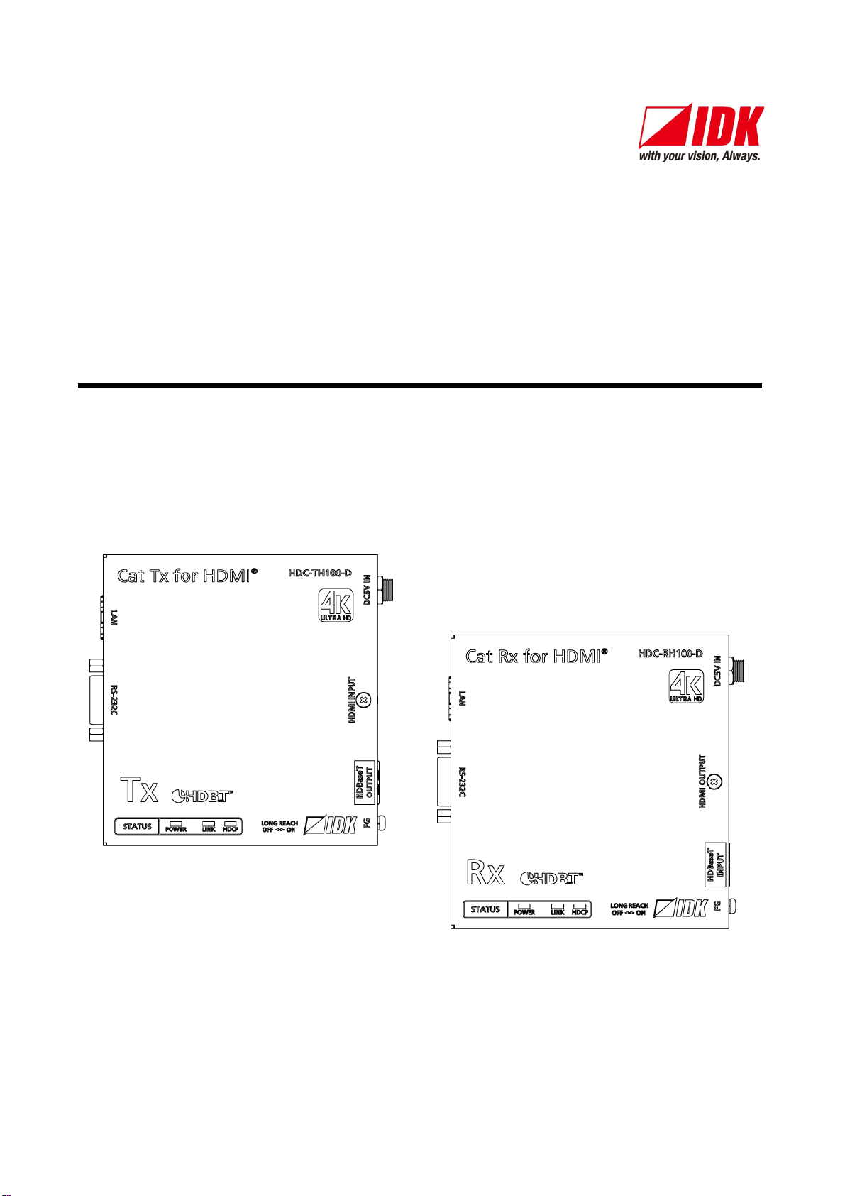
HDC-TH100-D / HDC-RH100-D User’s Guide
5
■For lifting heavy products:
Instruction
Lifting must be done by two or more personnel.
If you lift the product with your knees straight fully,
When lifting the product, bend your knees and get close to it with two or more persons; otherwise, your back may
be damaged.
■For installing and connecting products:
Prohibited
●Do not place the product in any unstable place.
Install the product in a horizontal and stable place. Otherwise, it may fall/turn over and lead to injury.
Secure the product if installing it at paces where there is much vibration.
Otherwise, it may move/fall and lead to injury.
Instruction
●Installation work must be done by the professionals.
The product is intended to be installed by skilled technicians. For installation, please contact a system integrator
or IDK. Improper installation may lead to the risk of fire, electric shock, injury, or property damage.
Set the power plug in a convenient place to unplug easily.
Unobstructed access to the plug enables unplugging the product in case of any extraordinary failure, abnormal
situation or for easy disconnection during extended periods of non-use.
Insert the power plug into an appropriate outlet completely.
If the plug is partially inserted, arching may cause the connection to overheat, increasing the risk of electrical
shock or fire. Do not use a damaged plug or connect to a damaged outlet.
Unplug the AC adapter when installing products.
When connecting devices, unplug all devices from outlets. Ground potential gap may cause fire or other
■For operating products:
Prohibited
●Keep out any foreign objects.
In order to avoid fire or electric shock, do not allow foreign objects, such as metal and paper, to enter the product
from the vent holes.
For power cable/ plug:
Do not scratch, heat, or modify, including lengthening them.
Do not pull, place heavy objects on them, or pinch them.
Do not bend, twist, or tie them together forcefully.
Misuse of the power cable and plug may cause fire or electric shock. If power cables/plugs become damaged,
contact your IDK representative.
Do not
●Do not repair, modify or disassemble.
Since the product includes circuitry
that uses potentially lethal, high voltage levels, disassembly byunauthorized
personnel may lead to the risk of fire or electric shock. For internal inspection or repair, contact your IDK
representative.
Do not touch
●Do not touch the product and connected cables while thunder lasts.
Contact may cause electric shock
Instruction
●Clean the power plug regularly.
If the plug is covered in dust, it may increase the risk of firer.