IFM SDG070 User manual

Operating instructions
Compressed air meters
SDG070
SDG080
SDG100
SDG150
SDG200
706375 / 00 12 / 2018
UK

2
Contents
1 Preliminary note���������������������������������������������������������������������������������������������������3
1�1 Symbols used ������������������������������������������������������������������������������������������������3
2 Safety instructions �����������������������������������������������������������������������������������������������3
3 Items supplied������������������������������������������������������������������������������������������������������4
4 Functions and features ����������������������������������������������������������������������������������������4
5 Function���������������������������������������������������������������������������������������������������������������5
5�1 Processing of the measured signals��������������������������������������������������������������5
5�2 Volumetric flow monitoring�����������������������������������������������������������������������������5
5�3 Consumed quantity monitoring (totalizer function) ����������������������������������������6
5�4 Switching function������������������������������������������������������������������������������������������6
5�5 Analogue function ������������������������������������������������������������������������������������������7
6 Installation������������������������������������������������������������������������������������������������������������8
6�1 Installation location ����������������������������������������������������������������������������������������8
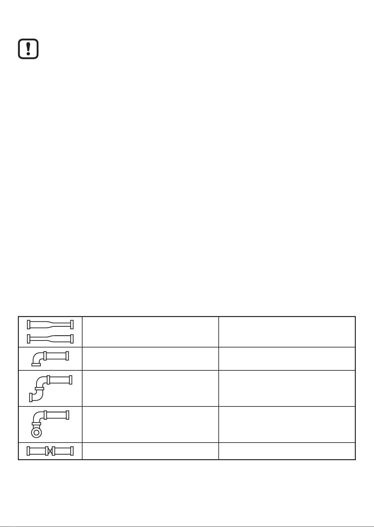
6�2 Installation conditions ������������������������������������������������������������������������������������8
6�3 Installation position ����������������������������������������������������������������������������������������9
6�4 Install the pipe section into the pipe ��������������������������������������������������������������9
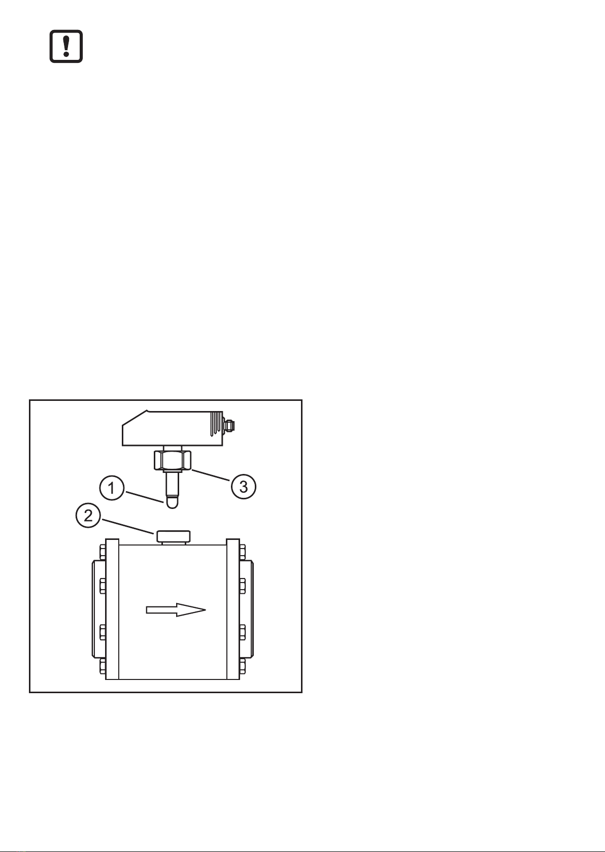
6�5 Insert the sensor into the pipe section���������������������������������������������������������10
7 Electrical connection������������������������������������������������������������������������������������������ 11
8 Operating and display elements ������������������������������������������������������������������������12
9 Menu������������������������������������������������������������������������������������������������������������������13
10 Parameter setting ��������������������������������������������������������������������������������������������15
10�1 General parameter setting�������������������������������������������������������������������������15
10�2 Settings for volumetric flow monitoring������������������������������������������������������16
10�2�1 Limit monitoring volumetric flow (OUT1) ������������������������������������������16
10�2�2 Limit monitoring volumetric flow (OUT2) ������������������������������������������16
10�2�3 Analogue output flow rate (OUT2) ����������������������������������������������������17
10�3 Settings for consumed quantity monitoring �����������������������������������������������17
10�3�1 Quantity monitoring by pulse output (OUT1) ������������������������������������17
10�3�2 Quantity monitoring by preset counter (OUT1)���������������������������������17
10�3�3 Manual counter reset������������������������������������������������������������������������17
10�3�4 Time-controlled counter reset �����������������������������������������������������������17
10�3�5 Deactivation of the counter reset������������������������������������������������������17

3
UK
10�3�6 Counter reset using an external signal ���������������������������������������������18
10�4 Settings for temperature monitoring ����������������������������������������������������������18
10�4�1 Limit monitoring temperature (OUT2)�����������������������������������������������18
10�4�2 Analogue output temperature (OUT2) ����������������������������������������������18
10�5 User settings (optional)������������������������������������������������������������������������������18
10�5�1 Standard unit of measurement for volumetric flow ���������������������������18
10�5�2 Standard display�������������������������������������������������������������������������������19
10�5�3 Measured value damping �����������������������������������������������������������������19
10�5�4 Error behaviour of the outputs ����������������������������������������������������������19
10�5�5 Setting of the standard pressure ������������������������������������������������������19
10�5�6 Setting of the standard temperature �������������������������������������������������19
10�5�7 Low flow cut-off���������������������������������������������������������������������������������20
10�6 Service functions ���������������������������������������������������������������������������������������20
10�6�1 Read min/max values �����������������������������������������������������������������������20
10�6�2 Restoring the factory settings �����������������������������������������������������������20
11 Operation ���������������������������������������������������������������������������������������������������������20
11�1 Reading of the set parameters�������������������������������������������������������������������20
11�2 Changing the display unit in the Run mode �����������������������������������������������21
11�3 Error indications�����������������������������������������������������������������������������������������21
11�4 General operating conditions���������������������������������������������������������������������21
12 Technical data and scale drawing��������������������������������������������������������������������21
1 Preliminary note
1.1 Symbols used
►Instruction
> Reaction, result
[…] Designation of pushbuttons, buttons or indications
→Cross-reference
Important note
Non-compliance can result in malfunction or interference�
2 Safety instructions
• Please read this document prior to set-up of the unit� Ensure that the product is
suitable for your application without any restrictions�

4
• If the operating instructions or the technical data are not adhered to, personal
injury and/or damage to property can occur�
• Ensure before mounting the components into or removing them from the
compressed air system that the installation is at a standstill and no pressure is
applied�
• Improper or non-intended use may lead to malfunctions of the unit or to un-
wanted effects in your application� That is why installation, electrical connec-
tion, set-up, operation and maintenance of the unit must only be carried out by
qualified personnel authorised by the machine operator�
• In order to guarantee the correct condition of the device for the operating time
the device must only be used in media to which the wetted parts are sufficiently
resistant (→ Technical data).
• The responsibility whether the measurement devices are suitable for the
respective application lies with the operator� The manufacturer assumes no
liability for consequences of misuse by the operator� Improper installation and
use of the devices result in a loss of the warranty claims�
3 Items supplied
1: flow sensor
2: pipe section
4 Functions and features
The unit monitors the standard volume flow of compressed air in industrial use�
It detects the process categories volumetric flow quantity and consumed quantity�

5
UK
Application area: compressed air systems in industrial use�
All indications apply for standard volume flow to DIN ISO 2533, i�e� volume flow
at 1013 hPa, 15 °C and 0 % relative air humidity� The unit can be set to different
standard conditions (→ 10.5.5 and → 10.5.6)�
The general operating conditions of compressed air equipment apply�
Pressure Equipment Directive (PED): Devices with a measuring section comply
with art� 3 sec� (3) of the Directive 97/23/EC and are designed and manufac-
tured for stable gases of the fluid group 2 in accordance with sound engineering
practice�
5 Function
5.1 Processing of the measured signals
• The unit displays the current process values�
• It generates 2 output signals according to the parameter setting�
OUT1 3 selection options ������������������������������������������������������ parameter setting
- switching signal for volumetric flow limit values ����������������������������� (→ 10.2.1)
- pulse sequence for quantity meter ������������������������������������������������ (→ 10.3.1)
- switching signal for preset counter ������������������������������������������������ (→ 10.3.2)
OUT2: 5 selection options
- switching signal for volumetric flow limit values ����������������������������� (→ 10.2.2)
- switching signal for temperature ����������������������������������������������������� (→ 10.4.1)
- analogue signal for volumetric flow quantity ���������������������������������� (→ 10.2.3)
- analogue signal for temperature ����������������������������������������������������� (→ 10.4.2)
- input for external counter reset signal �������������������������������������������� (→ 10.3.6)
5.2 Volumetric flow monitoring
The flow is monitored by a calorimetric measuring system�
• 2 switching signals for volumetric flow limit values can be provided (output 1
and output 2)� Switching functions → 5.4�
• An analogue signal which is proportional to the volumetric flow (4���20 mA) can
be provided on output 2� Analogue function → 5.5�

6
5.3 Consumed quantity monitoring (totalizer function)
The unit has an internal quantity meter which continuously totals the volumetric
flow� The sum corresponds to the current consumed quantity since the last reset�
• Output 1 can be configured as pulse output�
Output 1 provides a counting pulse each time when the value set in [ImPS] is
reached (→ 10.3)�
• The current meter reading can be displayed�
• In addition the value before the last reset is stored� This value can also be
displayed�
The meter saves the totalled consumed quantity every 10 minutes� After a power failure
this value is available as the current meter reading� If a time-controlled reset is set, the
elapsed time of the set reset interval is also stored� So the possible data loss can be
maximum 10 minutes�
The meter can be reset as follows:
• Manual reset (→ 10.3.3)
• Time-controlled automatic reset (→ 10.3.3)
• Reset after overflow (→ 10.3.5)
5.4 Switching function
OUTx changes its switching status if it is above or below the set switching limits�
Hysteresis or window function can be selected�
Hysteresis function Window function
SP
rP

7
UK
SP = set point
rP = reset point
HY = hysteresis
Hno = hysteresis NO (normally open)
Hnc = hysteresis NC (normally closed)
SP = upper limit
rP = lower limit
FE = window
Fno = window NO (normally open)
Fnc = window NC (normally closed)
When the hysteresis function is set, the set point [SP] is defined first and
then the reset point [rP] which must have a lower value� If only the set point
is changed, the reset point remains constant�
5.5 Analogue function
• The unit provides an analogue signal that is proportional to the volumetric flow
quantity and the medium temperature�
• Within the measuring range the analogue signal is 4���20 mA�
• The measuring range is scalable:
[ASP] determines at which measured value the output signal is 4 mA�
[AEP] determines at which measured value the output signal is 20 mA�
Minimum distance between [ASP] and [AEP] = 25 % of the final value of
the measuring range�
Factory setting Measuring range scaled
MEW = final value of the measuring range
Volumetric flow above the measuring range: output signal > 20 mA�
Volumetric flow below the measuring range: output signal between 3�6 and 4 mA�

8
6 Installation
►The rules and regulations for the installation and operation of com-
pressed air equipment must be observed�
►Ensure that no pressure is applied to the installation during mounting�
6.1 Installation location
• Behind the cold dryer / near the load�
• If compressed air is fed into the main pipe through parallel pipes, the unit
should be mounted in the main pipe�
• Installation after the maintenance unit is also possible (if oil is used for the
loads, the units must be mounted before the oiler)�
• Ensure sufficient clear space (min� 120 mm) for installation and removal of the
sensor�
6.2 Installation conditions
To meet the specified measurement accuracy, the defined inlet and outlet pipe
lengths must be adhered to:
• Inlet pipe length: 15 x pipe diameter�
• Outlet pipe length: 5 x pipe diameter�
In case of disturbances on the inflow side additional calming sections (B) are
recommended�
changes of the
pipe diameter B = 5 x pipe diameter (D)
90° elbow B = 5 x pipe diameter (D)
two 90° elbows, one plane B = 10 x pipe diameter (D)
two 90° elbows, two planes B = 15 x pipe diameter (D)
valve, slide B = 35 x pipe diameter (D)

9
UK
6.3 Installation position
• Permitted installation positions: pipe length vertical, any position (fig� 1, 2), pipe
length horizontal, unit vertical (fig� 3, 4), unit on side, pipe length left (fig� 5)�
• Avoid the installation position in fig� 6 (unit on side, pipe length right)� If the flow
rate is low, the specified measurement accuracy cannot be adhered to�
F
F
1 2 3 5
4 6
F = flow direction
6.4 Install the pipe section into the pipe
IN OUT
►Loosen the screws (1) on the flanges, remove the flanges (2) from the measur-
ing section (4)�
►Remove the seals (3) from the flange slots�
►Weld the flanges into the pipe�

10
The welding operation must be carried out by authorised personnel�
The flanges must be welded without distortion�
In order to prevent a dissimilar metal weld, pipe and flange must be of
the same material�
After welding
►Let the pipe and flanges cool down�
►Remove any welding residues from the welding seams� Especially the inner
surface of the pipe should be free from burrs so that the measurement ac-
curacy is not impaired�
►Insert the seals into the flange slots� Note: The slot must be clean and free
from welding residues�
►Insert the measuring length so that the flow direction and the arrow (5) show in
the same direction�
►Insert the screws and tighten�
6.5 Insert the sensor into the pipe section
►Remove the protective cover
from the measuring probe of the
sensor (1)�
►Insert the sensor into the meas-
urement connection (2)�
►Align the sensor: parallel to the
pipe section, connector in the
direction of the arrow on the pipe
section�
►Tighten the nut (3)� Tightening
torque max� 50 Nm� When do-
ing so, keep the position of the
sensor�

11
UK
7 Electrical connection
The unit must be connected by a qualified electrician�
The national and international regulations for the installation of electrical
equipment must be adhered to�
Voltage supply according to EN 50178, SELV, PELV�
►Disconnect power�
►Connect the unit as follows:
43
2 1
BK: black
BN: brown
BU: blue
WH: white
BN
WH
BK
BU
4
1
3
2OUT2
L+
L
OUT1
Colours to DIN EN 60947-5-6
Sample circuits:
2 x positive switching 1 x positive switching / 1 x analogue
L
L+
3 BU
4 BK
2 WH
1 BN
L+
L
3 BU
4 BK
2 WH
1 BN
Pin 1 L+
Pin 3 L-
Pin 4
(OUT1)
• Switching signal: limit values for volumetric flow
• Pulse signal: 1 pulse every time the defined volumetric flow quantity is reached�
• Switching signal: quantity meter reached preset value
Pin 2
(OUT2)
• Switching signal: limit values for volumetric flow
• Switching signal: limit values for temperature
• Analogue signal for volumetric flow quantity
• Analogue signal for temperature
• Input for external counter reset signal

12
8 Operating and display elements
9
10 11
SP1
SP2
10
3
°C
Mode/Enter Set
Nm/s
Nm
3
Nm
3
/h
N
l/min
123 4 5 6 78
1 to 8: Indicator LEDs
- LED 1���6: process value in the indicated unit of measurement
- LED 7, LED 8: switching state of the corresponding output�
9: Alphanumeric display, 4 digits
- Current flow volume
- Current medium temperature
- Current consumed quantity (= meter reading)
- Consumed quantity (= meter reading) before the last reset
- Display of the parameters and parameter values
10: Mode/Enter button
- Selection of the parameters and acknowledgement of the parameter values�
11: Set pushbutton
- Setting of the parameter values (scrolling by holding pressed; incrementally by pressing
once)�
- Change of the display unit in the normal operating mode (Run mode)�
For units ≥ DN150 the displayed totaliser value has to be multiplied by the
factor 1000�

13
UK
9 Menu
ASP
OU2
SP1
rP1
OU1
SP2
ImPS
ImPR
DIn2
EF
AEP rP2
Hno Hnc Fno Fnc ImP
IHno Hnc Fno Fnc In.D
RUN
Nm
3
/h Nm/s Nl/min x 10
3
Nm
3
Nm
3
* °C
[Mode / Enter]
[Set]
HI
LO
FOU1
FOU2
dAP
rTo
diS
Uni
SELd
SEL2
rEF.P
rEF.T
LFC
rES
EF
Nm3(LED is lit) = current meter reading
Nm3* (LED flashes) = stored meter reading

14
Explanation of the menu
ImPS Pulse value (consumed quantity at which 1 pulse is delivered)
ImPR Configuration of the output for consumed quantity monitoring:
YES (pulse signal), no (switching signal)
SP1 / rP1 Upper / lower limit value for the volumetric flow at which OUT1 switches
OU1
Output function for OUT1 (volumetric flow):
- Hno, Hnc, Fno, Fnc: switching signal for the limits
- ImP: consumed quantity monitoring (totaliser function)
OU2
Output function for OUT2 (volumetric flow or temperature):
- Hno, Hnc, Fno, Fnc: switching signal for the limits
- I (current signal 4���20 mA)
Input function for OUT2:
- In�D: input for external meter reset signal
SP2 / rP2 Upper / lower limit value at which OUT2 switches�
ASP / AEP Analogue start point / analogue end point for volumetric flow or
temperature on OUT2
DIn2 Configuration of the input for external meter reset signal:
HIGH, +EDG, LOW, -EDG
EF Extended functions / opening of menu level 2
HI / LO Maximum / minimum value memory for volumetric flow
FOU1 / FOU2 Behaviour of OUT1 / OUT2 in case of an internal fault:
OU, On, OFF
dAP Measured value damping: damping constant in seconds
rTo Counter reset: manual reset / time-controlled reset
diS Update rate and orientation of the display
Uni Standard unit of measurement for volumetric flow: Nl/min, Nm3/h, Nm/s
SELd Standard measured variable of the display: FLOW (volumetric flow value),
TEMP (medium temperature), TOTL (meter reading)
SEL2 Standard unit of measurement for evaluation by OUT2:
FLOW (volumetric flow) or TEMP (temperature)
rEF�P Standard pressure to which the measured and display values for volumet-
ric flow refer
rEF�T Standard temperature to which the measured and display values for
volumetric flow refer
LFC Low flow cut-off
rES Restoring the factory settings

15
UK
10 Parameter setting
During parameter setting the unit remains in the operating mode� It continues its
monitoring function with the existing parameters until the parameter setting has
been completed�
10.1 General parameter setting
3 steps must be taken for each parameter setting:
1Select parameter
►Press [Mode/Enter] until the re-
quested parameter is displayed.
2Setting of the parameter value
►Press [Set] and keep it pressed�
> Current setting value of the param-
eter flashes for 5 s�
> After 5 s: setting value is changed:
incrementally by pressing the button
once or continuously by keeping the
button pressed�
Numerical values are incremented continuously� To reduce the value: let the display
move to the maximum setting value� Then the cycle starts again at the minimum
setting value�
3Acknowledge parameter value
►Press [Mode/Enter] briefly�
> The parameter is displayed again�
The new setting value is stored�
Setting of other parameters
►Start again with step 1�
Finishing the parameter setting
►Press [Mode/Enter] several times until the current measured value is displayed or wait
for 15
s�
> The unit returns to the operating mode�

16
• Change from menu level 1 to menu level 2:
►Press [Mode/Enter] until [EF] is
displayed.
►Press [Set] briefly�
> The first parameter of the submenu is
displayed (here: [HI])�
• Locking / unlocking
The unit can be locked electronically to prevent unintentional settings�
►Make sure that the unit is in the
normal operating mode�
►Press [Mode/Enter] + [Set] for 10 s�
> [Loc] is displayed�
During operation: [LOC] is briefly displayed if you try to change parameter values�
For unlocking:
►Press [Mode/Enter] + [Set] for 10 s�
> [uLoc] is displayed�
On delivery: unlocked�
• Timeout:
If no button is pressed for 15 s during parameter setting, the unit returns to the operat-
ing mode with unchanged values�
10.2 Settings for volumetric flow monitoring
10.2.1 Limit monitoring volumetric flow (OUT1)
►Select [OU1] and set the switching function: Hno, Hnc, Fno or Fnc�
►Select [SP1] and set the upper limit of the volumetric flow�
►Select [rP1] and set the lower limit of the volumetric flow�
10.2.2 Limit monitoring volumetric flow (OUT2)
►Select [SEL2] and set FLOW�
►Select [OU2] and set the switching function: Hno, Hnc, Fno or Fnc�
►Select [SP2] and set the upper limit of the volumetric flow�
►Select [rP2] and set the lower limit of the volumetric flow�

17
UK
10.2.3 Analogue output flow rate (OUT2)
►Select [SEL2] and set FLOW�
►Select [OU2 ] and set the analogue function: I (4���20 mA)�
►Select [ASP2] and set the volumetric flow value at which the minimum current value is
provided�
►Select [AEP2] and set the volumetric flow value at which the maximum current value
is provided�
10.3 Settings for consumed quantity monitoring
10.3.1 Quantity monitoring by pulse output (OUT1)
►Select [OU1] and set ImP�
►Select [ImPR] and set YES�
►Select [ImPS] and set the volumetric flow quantity at which 1 pulse is provided�
10.3.2 Quantity monitoring by preset counter (OUT1)
►Select [OU1] and set ImP�
►Select [ImPR] and set no�
►Select [ImPS] and set the volumetric flow quantity at which output 1 switches�
10.3.3 Manual counter reset
►Select [rTo] and set rES�T�
> The counter is reset to zero�
10.3.4 Time-controlled counter reset
►Select [rTo] and set the requested value (intervals of hours, days or weeks)�
> The counter is reset automatically with the value now set�
10.3.5 Deactivation of the counter reset
►Select [rTo] and set OFF�
> The meter is only reset after overflow (= factory setting)�

18
10.3.6 Counter reset using an external signal
►Select [OU2] and set In�D�
►Select [DIn2] and set the counter reset signal:
HIGH = reset for high signal
LOW = reset for low signal
+EDG = reset for rising edge
-EDG = reset for falling edge
10.4 Settings for temperature monitoring
10.4.1 Limit monitoring temperature (OUT2)
►Select [SEL2] and set TEMP�
►Select [OU2] and set the switching function: Hno, Hnc, Fno or Fnc�
►Select [SP1] and set the upper temperature limit�
►Select [rP2] and set the lower temperature limit�
10.4.2 Analogue output temperature (OUT2)
►Select [SEL2] and set TEMP�
►Select [OU2 ] and set the analogue function: I (4���20 mA)�
►Select [ASP2] and set the temperature value at which the minimum current value is
provided�
►Select [AEP2] and set the temperature value at which the maximum current value is
provided�
10.5 User settings (optional)
10.5.1 Standard unit of measurement for volumetric flow
►Select [uni] and set the unit of measurement�
The setting only has an effect on the volumetric flow value� The consumed quantity
(meter reading) is automatically displayed in the unit of measurement providing the
highest accuracy�

19
UK
10.5.2 Standard display
►Select [SELd] and define the standard unit of measurement
FLOW = display shows the current volumetric flow value in the standard unit of meas-
urement�
TOTL = display shows the current meter reading in the unit providing the highest ac-
curacy�
TEMP = the current medium temperature in °C is displayed�
►Select [diS] and set the update rate and orientation of the display:
d1 = update of the measured values every 50 ms�
d2 = update of the measured values every 200 ms�
d3 = update of the measured values every 600 ms�
rd1, rd2, rd3 = display like d1, d2, d3; rotated by 180�
OFF = the display is switched off in the operating mode� The LEDs remain active
even if the display is deactivated� Error messages are displayed even if the display is
deactivated�
10.5.3 Measured value damping
► Select [dAP] and set the damping constant in seconds (τ value 63 %).
10.5.4 Error behaviour of the outputs
►Select [FOU1] and set the value:
- On = Output 1 switches ON in case of a fault�
- OFF = Output 1 switches OFF in case of an error�
- OU = Output 1 switches irrespective of the fault as defined with the parameters�
►Select [FOU2] and set the value:
1� Switching output:
- On = Output 2 switches ON in case of a fault�
- OFF = Output 2 switches OFF in case of a fault�
- OU = Output 2 switches irrespective of the fault as defined with the parameters�
2� Analogue output:
- On = The analogue signal goes to the upper fault value�
OFF = The analogue value goes to the lower fault value�
OU = The analogue signal corresponds to the measured value�
10.5.5 Setting of the standard pressure
►Select [rEF�P] and set the requested standard pressure�
10.5.6 Setting of the standard temperature
►Select [rEF�T] and set the requested standard temperature�

20
10.5.7 Low flow cut-off
►Select [LFC] and set the limit�
10.6 Service functions
10.6.1 Read min/max values
Read minimum or maximum measured values:
►Select HI or LO
HI = maximum volumetric flow, LO = minimum volumetric flow
Delete memory:
►Select HI or LO�
►Press and hold [Set] until [----] is displayed�
►Briefly press [Mode/Enter]�
It makes sense to delete the memories as soon as the unit operates under normal
operating conditions for the first time�
10.6.2 Restoring the factory settings
►Select [rES]�
►Press and hold [Set] until [----] is displayed�
►Briefly press [Mode/Enter]�
11 Operation
Correct operation and compliance with the measurement accuracy can only be en-
sured if the environmental conditions specified in the "Technical data" are adhered
to� Ensure that the maximum pressure range, measuring range and permitted
operating temperature are not exceeded�
After power on and expiry of the power-on delay time (approx� 0�5 s) the unit is in
the Run mode (= normal operating mode)� It carries out its measurement and eval-
uation functions and generates output signals according to the set parameters�
• Operating indications → 8 Operating and display elements�
• During the power-on delay time the outputs are switched as programmed: ON
for NO function (Hno / Fno), OFF for NC function (Hnc / Fnc)�
• If output 2 is configured as analogue output, the output signal is at the final
value of the measuring range during the power-on delay time�
11.1 Reading of the set parameters
►Press [Mode/Enter] until the requested parameter is displayed�
This manual suits for next models
4
Table of contents
Other IFM Measuring Instrument manuals