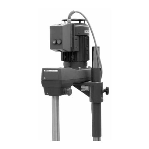
IKA T 65 D User manual

Artisan Technology Group is your source for quality
new and certied-used/pre-owned equipment
• FAST SHIPPING AND
DELIVERY
• TENS OF THOUSANDS OF
IN-STOCK ITEMS
• EQUIPMENT DEMOS
• HUNDREDS OF
MANUFACTURERS
SUPPORTED
• LEASING/MONTHLY
RENTALS
• ITAR CERTIFIED
SECURE ASSET SOLUTIONS
SERVICE CENTER REPAIRS
Experienced engineers and technicians on staff
at our full-service, in-house repair center
WE BUY USED EQUIPMENT
Sell your excess, underutilized, and idle used equipment
We also offer credit for buy-backs and trade-ins
www.artisantg.com/WeBuyEquipment
REMOTE INSPECTION
Remotely inspect equipment before purchasing with
our interactive website at www.instraview.com
LOOKING FOR MORE INFORMATION?
Visit us on the web at www.artisantg.com for more
information on price quotations, drivers, technical
specications, manuals, and documentation
Contact us: (888) 88-SOURCE | sales@artisantg.com | www.artisantg.com
SM
View
Instra

15 821 01 a IKAWERKE
IKA® T 65 D Dispersion unit
OPERATING INSTRUCTIONS EN/
USA
T 65D 042005
Artisan Technology Group - Quality Instrumentation ... Guaranteed | (888) 88-SOURCE | www.artisantg.com

Artisan Technology Group - Quality Instrumentation ... Guaranteed | (888) 88-SOURCE | www.artisantg.com

IKA-WERKE T 65 D 042005
CE-KONFORMITÄTSERKLÄRUNG DE
Wir erklären in alleiniger Verantwortung, dass dieses Produkt den Bestimmungen
der Richtlinien 89/336EG, 98/37/EG und 73/023EG entspricht und mit den
folgenden Normen und norminativen Dokumenten übereinstimmt:
DIN EN 61 010-1; EN 60 204-1; EN 292-1, -2; EN 414; EN 61 326-1.
CE-DECLARATION OF CONFIRMITY EN
We declare under our sole responsibility that this product corresponds to the
regulations 89/336EG, 98/37/EG and 73/023EG and conforms with the standards or
standardized documents:
DIN EN 61 010-1; EN 60 204-1; EN 292-1, -2; EN 414; EN 61 326-1.
DÉCLARATION DE CONFORMITÉ CE FR
Nous déclarons sous notre propre responsabilité que se prodiut est conforme aux
réglementations 89/336EG, 98/37/EG et 73/023EG et en conformité avec les
normes ou documents normalisés suivant:
DIN EN 61 010-1; EN 60 204-1; EN 292-1, -2; EN 414; EN 61 326-1.
DECLARACION DE CONFORMIDAD DE CE ES
Declaramos por nuestra responsabilidad propia que este produkto corresponde a
las directrices 89/336EG, 98/37/EG y 73/023EG y que cumple las normas o
documentos normativos siguientes:
DIN EN 61 010-1; EN 60 204-1; EN 292-1, -2; EN 414; EN 61 326-1.
CE-DICHIARAZIONE DI CONFORMITÀ IT
Dichiariamo, assumendone la piena responsabilità, che il prodotto è conforme alle
seguenti direttive: 89/336EG, 98/37/EG e 73/023EG, in accordo ai seguenti
regolamenti e documenti:
DIN EN 61 010-1; EN 60 204-1; EN 292-1, -2; EN 414; EN 61 326-1.
Artisan Technology Group - Quality Instrumentation ... Guaranteed | (888) 88-SOURCE | www.artisantg.com

IKA-WERKE T 65 D 042005
Explanation of symbols
This symbol identifies information that is of vital importance for safeguarding
your health and safety. Disregarding this information can lead to health impairment
and injuries.
This symbol identifies information that is of importance for the technically
correct functioning of the system. Disregarding this information can result in
damage to the T 65 D dispersion unit or to system components.
This symbol identifies information and notes that are of importance for correct
handling of the T 65 D dispersion unit.
+
Artisan Technology Group - Quality Instrumentation ... Guaranteed | (888) 88-SOURCE | www.artisantg.com

IKA-WERKE T 65 D 042005
Page I-1
Contents
Page
1Notes for the user .................................................................... 1-1
1.1 Correct use............................................................................ 1-1
1.2 For your safety........................................................................ 1-1
1.3 Guarantee.............................................................................. 1-2
2Product description.................................................................. 2-1
2.1 The T 65 D dispersion unit........................................................ 2-1
2.2 Dispersion tools in the S 65 range ............................................. 2-2
2.3 T 653 telescopic stand............................................................. 2-3
3Set-up and commissioning ....................................................... 3-1
3.1 Unpacking.............................................................................. 3-1
3.2 Assembly and electrical installation of the dispersion unit............. 3-1
3.3 Mounting the safety limit switch................................................. 3-2
3.4 Pre-assembly of dispersion tools ............................................... 3-2
3.5 Mounting the dispersion tool on the unit ..................................... 3-4
3.6 Switching the unit on ............................................................... 3-5
4Maintenance and care............................................................... 4-1
4.1 T 65 D dispersion unit.............................................................. 4-1
4.2 Dispersion tools ...................................................................... 4-2
4.3 Changing the slide ring seal...................................................... 4-3
5Technical data.......................................................................... 5-1
5.1 T 65 D dispersion unit technical data ......................................... 5-1
5.2 S 65 dispersion tool technical data ............................................ 5-2
6Accessories............................................................................. 6-1
7Appendix ................................................................................. 7-1
7.1 T 65 D dispersion unit spare parts diagram and list...................... 7-1
7.2 S 65 range spare parts diagram and list..................................... 7-2
7.3 Wiring diagram of T 65 D dispersion unit .................................... 7-3
7.4 Applicable standards and regulations......................................... 7-4
7.5 The T 653 telescopic stand....................................................... 7-5
Artisan Technology Group - Quality Instrumentation ... Guaranteed | (888) 88-SOURCE | www.artisantg.com

IKA-WERKE T 65 D 042005
Artisan Technology Group - Quality Instrumentation ... Guaranteed | (888) 88-SOURCE | www.artisantg.com

IKA-WERKE T 65 D 042005
Page 1-1
1Notes for the user
1.1 Correct use
The T 65 D dispersion unit, used in conjunction with the IKAdispersion tools, is
suitable for mixing, emulsifying and dispersing free-flowing and liquid media in batch
operation. It is designed for use in technical colleges and for small-scale production.
For operation, the T 65 D dispersion unit must be mounted on the T 653 telescopic
stand. It must only be used with dispersion tools from the S 65 range.
1.2 For your safety
For correct use, the unit must be secured on the T 653 telescopic stand by two
bolts, in accordance with Section 3 "Set-up and commissioning". The telescopic
stand must be installed so that it cannot topple over or slide about, and must be
equipped with a safety disconnection device which operates when the stand is
moved upwards. In particular, please also read the safety notes for use of the
telescopic stand (see Appendix, Section 7.5, "The T 653 telescopic stand).
The unit is not suitable for manual operation. Please observe the applicable
safety notes and directives, as well as health and safety regulations and
safety rules for use in the laboratory.
If the emergency stop switch of the dispersion unit is not within reach when
the unit is operating, an additional emergency stop switch must be installed
within easy reach, in the working area.
During operation never touch the dispersion tools to avoid injury. Some
dispersion tools have overlapping cutting edges and teeth.
When working with the dispersion unit, the user must select and wear his/her
personal protection equipment to suit the danger class of the product to be
mixed. With faulty or unsuitable protection equipment, the user can be
endangered due to splashing.
The T 65 D dispersion unit must not be used in hazardous areas, for
dispersing hazardous substances, or used for operation under water.
The T 65 D dispersion unit must not be used for processing any inflammable
or combustible materials.
Only dispersion tools approved by IKA
for this unit must be used.
Imbalance of the dispersion unit tool shaft can lead to uncontrolled resonance
behaviour of the unit and the entire installation. Glass apparatus and vessels can be
damaged or can shatter, and if this happens, the user could be injured. If uneven
running of the unit is noticed, the dispersion tool should be checked and replaced if
necessary.
The vessels used for the dispersing process must be secured. Glass vessels must
always be secured with a clamp to prevent them spinning. When working in glass
vessels, the dispersion tool must not come into contact with the glass. Either elastic
couplers must be used when working with flasks, or sufficient clearance maintained
between dispersion tool and vessel, in order to avoid glass breakage.
Operating
conditions
Danger due to
glass breakage
Artisan Technology Group - Quality Instrumentation ... Guaranteed | (888) 88-SOURCE | www.artisantg.com

1 Notes for the user
IKA-WERKE T 65 D 042005
Page 1-2
In some circumstances, the region between medium and drive shaft, or between
rotor and stator, can become electrostatically charged, and ignite an explosive
atmosphere caused by evaporation of the medium. In addition, with advanced
evaporation of the medium, the slide ring seal can overheat to such an extent that it
would lead to an ignition or combustion of the medium.
For this reason, no inflammable or combustible materials must be processed with
the T 65 D dispersion unit.
Before commissioning, the unit must be wired up by a skilled worker.
Even in the case of repair work, the unit must only be opened by a skilled worker.
Before opening, the mains plug must be pulled out. Live parts inside the unit can
remain live for a long time after the mains plug is pulled out.
The accessory must only be fitted after the mains plug is disconnected.
The handwheel bolt on the flange of the drive unit can become loose due to
vibration. For safety's sake, check the tightness of the handwheel bolt regularly, and
retighten it if necessary.
Before commissioning, the correct direction of rotation of the motor must always be
ensured (test run without dispersion tool: motor rotation as indicated on the arrow
plate, or clockwise rotation, looking down on motor). The wrong direction of rotation
can lead to the rotor or stator coming off the shaft.
If the unit is operated in different locations with a 5-pin plug, the direction of rotation
must be checked before commissioning, with no dispersion tool fitted.
Ventilation slots and cooling vanes on the motor must not be covered.
Avoid shocks or impacts on the dispersion tool. Even slight, undetectable damage
leads to imbalance and uneven running of the drive shaft. Careful handling ensures
the safe operation and durability of the unit.
If possible, only switch on the drive with the lowest speed (in combination with a
speed controller DS). Increase the speed slowly to the desired value.
Dispersion tools must only be operated in the medium. The sealing surfaces are
cooled by the free-flowing medium. Running dry destroys the sealing surfaces.
Never use the dispersing unit without dispersion tools.
Rapid temperature change (thermal shock!) can destroy the hard metal sealing
surfaces.
In order to avoid high risk of injury never touch the dispersion tool during operation!
Some dispersion tools have prominent blades and teeth.
1.3 Guarantee
You have purchased an original IKA laboratory machine which meets the highest
engineering and quality standards. In accordance with IKA guarantee conditions, the
guarantee period is 24 months. For claims under the guarantee please contact your
local dealer. You may also send the machine direct to our works, enclosing the
delivery invoice and giving reasons for the claim. You will be liable for freight costs.
Danger due to
electric shock
Checking the
handwheel bolt
Impairment of
the machine
function
Observe
direction of
rotation of
the motor
Danger due to
explosion or
overheating
Artisan Technology Group - Quality Instrumentation ... Guaranteed | (888) 88-SOURCE | www.artisantg.com

IKA-WERKE T 65 D 042005
Page 2-1
2Product description
2.1 The T 65 D dispersion unit
The IKAT 65 D dispersion unit is a high-quality product that guarantees trouble-
free use, as a result of the sturdy unit construction and the simple operation. The
drive shaft - driven by a Poly-V-belt – has a fixed speed of 7200 r.p.m. and, in turn,
drives the rotor. As a result, the S 65 range of dispersion tools that can be used
achieve tip speeds of 21.9 m/sec. These tip speeds lead to optimal dispersing or
emulsifying results in batch operation.
For operation, the T 65 D dispersion unit must be mounted on the IKAT 653
telescopic stand. It must only be operated with the S 65 KG-HH shaft and the
dispersion tools from the S 65 range (G 65 G, G 65 M, G 65 F). The unit is switched
on and off by pressing the ON button (A) and the emergency stop button (B). If the
emergency stop switch of the dispersion unit is not within reach, an additional
emergency stop switch must be installed within easy reach, in the working area.
If the telescopic stand is moved upwards when the unit is operating, the dispersion
unit must switch off. To facilitate this, the telescopic stand must be equipped with a
safety disconnection device. For this purpose, we recommend the installation of the
SI 400 safety limit switch together with the SI 400 mounting support (accessories).
Safety
disconnection
device
Artisan Technology Group - Quality Instrumentation ... Guaranteed | (888) 88-SOURCE | www.artisantg.com

2 Product description
IKA-WERKE T 65 D 042005
Page 2-2
The unit is supplied without connecting cable, as the installations on the user's
premises do not permit a standard cable length, because of the different
accommodating spaces. The layout of connections is shown in the wiring diagram
(see Section 6.3 "Wiring diagram"), for the information of skilled workers.
The unit heats up in service. The generously-proportioned cooling surfaces on the
motor achieve an even distribution and emission of the heat.
The AC motor runs in ball bearings and is maintenance-free. In its attached control
cabinet, it has a special safety device for operation on overcurrent and undervoltage
(undervoltage trip), to permanently switch the motor off and avoid any thermal
damage. The unit can only be put back in service when the power supply required
for the motor is restored.
The basic connection and performance data for the motor can be obtained from the
motor rating plate.
The connection facility for the IKASI 400 safety limit switch is also provided in the
motor control cabinet.
2.2 Dispersion tools in the S 65 range
A dispersion tool in the S 65 range consists of a shaft and a generator (stator/rotor).
The shaft carries the marking S 65 KG-HH, where KG stands for the ball bearing
and HH for a slide ring seal made of hard metal. The seal prevents liquid rising up
the shaft and destroying the ball bearing. The top end of the shaft is in the form of a
plug-in coupling. The bottom end of the shaft carries a thread for mounting the
stator. The shaft – running in ball bearings- carries the rotor.
For the S 65 range, there are three types of generator, designated G65 G, G65 M,
G65 F, where the prefix G stands for generator and the suffices G for coarse, M for
medium and F for fine. The appropriate generator must be used according to the
medium. When the starting material is too coarse for the generator, the generator
can clog up and hence become ineffective. In addition, the sealing surfaces run dry,
so that they are damaged.
The generators are suitable for solids components with the following grain sizes:
Generator type Grain size
G 65 G 40 mm
G 65 M 8 mm
G 65 F 1 mm
It can often be helpful to process a medium with all three generators in sequence,
starting with generator G 65 G. Although it is easy to change the generators, in such
cases, it is worth buying three shafts, that can then be changed with fewer
manipulations.
Motor
protection
Wiring by
skilled worker
Artisan Technology Group - Quality Instrumentation ... Guaranteed | (888) 88-SOURCE | www.artisantg.com

IKA-WERKE T 65 D 042005
Page 2-3
Due to the high rotation speed of the rotor, the medium to be processed is
automatically drawn axially into the dispersion head and then forced radially through
the slots in the rotor/stator arrangement. The high accelerations acting on the
material produce extremely strong shear and thrust forces. In addition, high
turbulence occurs in the shear gap between rotor and stator, which provides
optimum mixing of the suspension.
The dispersion effectiveness is heavily dependent on the product of the shear
gradient and the time the particles spend in the shear zone. The optimum range for
the circumferential velocity of the rotor/stator arrangement is 10 to 24 m/s.
A processing time of a few minutes is usually sufficient to produce the desired
fineness. Long prccessing times bring only insignificant improvements in the
obtainable fineness; the energy expended serves merely to increase the
temperature of the medium.
With small quantities, a rapid heating-up of the medium must be expected,
because of the high motor power, which is mainly converted into heat.
If the viscosity of the material to be processed is too high (above about 5
Pas.), or the vapour pressure of the liquid is very high, the flow is unable to
follow the rapid accelerations of the generator, and breaks down. This leads to
dry running, and hence to destruction of the sealing surfaces. Such
substances must be fed to the generator by force. Use a continuous flow unit
(i.e. IKALaborpilot) for this, and/or an additional pump.
2.3 T 653 telescopic stand
In conjunction with the IKAT 653 telescopic stand, the T 65 D dispersion unit can
also be used for tall mixing vessels. For information on this product, please refer to
the Appendix to this document.
The rotor/stator
principle
Artisan Technology Group - Quality Instrumentation ... Guaranteed | (888) 88-SOURCE | www.artisantg.com

IKA-WERKE T 65 D 042005
Artisan Technology Group - Quality Instrumentation ... Guaranteed | (888) 88-SOURCE | www.artisantg.com

IKA-WERKE T 65 D 042005
Page 3-1
3Set-up and commissioning
3.1 Unpacking
Please unpack the system components carefully and check closely for any damage.
It is important to recognize any damage that occurred during shipping while you are
unpacking. If damage has occurred, you will need to make a written assessment of
the damage and send it to us by mail, rail or special delivery.
The delivery package of the unit comprises: one T 65 D dispersion unit
corresponding to the type ordered (see Section 5, "Technical data"), one set of tools
and one set of operating instructions.
3.2 Assembly and electrical installation of the dispersion unit
As shown in the diagram, the T 65 D dispersion unit is mounted on the T 653
telescopic stand with two M12 hexagon socket head (Allen) screws and toothed lock
washers. The screws and toothed lock washers are included in the delivery package
of the stand. An assistant is required for screwing on the T 65 D dispersion unit.
Mounting the
dispersion unit
Artisan Technology Group - Quality Instrumentation ... Guaranteed | (888) 88-SOURCE | www.artisantg.com

3 Set-up and commissioning
IKA-WERKE T 65 D 042005
Page 3-2
The telescopic stand must be installed such that it does not tilt or slide about.
It must not move about when the unit is operating.
Particular danger points, such as crushing/trapping positions, rotating parts,
locking screws for the stand column, are identified by an exclamation mark in
the “Dispersion unit assembly” diagram. Particular regard should be paid to
these danger points when the unit is in service!
The electrical connections of the T 65 D dispersion unit must be made by a skilled
worker in accordance with the wiring diagram (see Section 6.3, “Wiring diagram”).
3.3 Mounting the safety limit switch
There is a danger of trapping between the safety limit switch, switch contact
and the end stop!
Mount the SI 400 safety limit switch together with the SI 474 mounting support on
the T 653 telescopic stand. For this, follow the mounting instructions on the next
page.
3.4 Pre-assembly of dispersion tools
Before the dispersion tools are connected to the dispersion unit, the shaft and
generator are pre-assembled. The following tools (set of tools included in the T 65 D
delivery package) are required to change the generator:
Rotor wrench
Hook wrench
Shaft wrench
The slide ring seal must be correctly fitted before pre-assembly of the shaft
and generator.
Artisan Technology Group - Quality Instrumentation ... Guaranteed | (888) 88-SOURCE | www.artisantg.com

IKA-WERKE T 65 D 042005
Page 3-3
Artisan Technology Group - Quality Instrumentation ... Guaranteed | (888) 88-SOURCE | www.artisantg.com

3 Set-up and commissioning
IKA-WERKE T 65 D 042005
Page 3-4
Assemble the generator on the shaft as follows:
1. Screw the stator on to the stator tube counterclockwise by hand. Note the left-
hand thread!
2. Gently tighten the stator with the hook wrench. The stator is turned in the same
direction later, by the flow pressure of the rotor, and hence cannot come loose.
3. Screw the rotor clockwise on to the shaft (right-hand thread). To do this, hold
the shaft with the shaft wrench at the coupling section and tighten the rotor with
the rotor wrench. With the G65 G generator, the rotor wrench is inserted
between the teeth of the stator and turned.
3.5 Mounting the dispersion tool on the unit
The dispersion tool must only be mounted on the dispersion unit when the
mains plug is pulled out and the drive shaft is stationary.
The pre-assembled element, consisting of shaft and generator, is now connected to
the T 65 D dispersion unit. To do this, insert the pre-assembled dispersion tool in the
dispersion tool receptacle (C) and secure it with the handwheel bolt. Make sure that
the shaft is inserted right up to the stop in the receptacle. It can be helpful to turn the
shaft lightly as it is inserted. The tool is locked in position by tightening the
handwheel bolt. Make sure that the handwheel bolt is securely tightened, and also
check the tightness frequently when the unit is in service.
Artisan Technology Group - Quality Instrumentation ... Guaranteed | (888) 88-SOURCE | www.artisantg.com

IKA-WERKE T 65 D 042005
Page 3-5
3.6 Switching the unit on
Check that the voltage stated on the rating plate matches the available mains
supply voltage. The socket used must be earthed (protective earth contact). If
these condition are fulfilled, the unit is ready for service, after the mains plug
is inserted. Otherwise, safe operation cannot be guaranteed, or the unit can be
damaged.
Before switching the unit on, the dispersion tool must be immersed to the minimum
immersion depth in the medium (see Section 5, “Technical data”). Because of the
suction effect, the clearance to the base of the vessel must not be less than 30 mm.
The dispersion tool must be brought into the vessel off-centre, to avoid rotational
turbulence (vortexing).
For safety's sake, the vessel must always be well secured.
When operating with the SI 400 safety limit switch, the unit is only ready for service
when it has been locked in position at the planned working height and the switch
contact operates the safety limit switch.
The unit is started by pressing the ON button (A).
The unit is stopped by pressing the EMERGENCY STOP button (B).
After an interruption in the power supply, or a mechanical interruption during a
dispersing process, the unit does not automatically re-start.
+
Artisan Technology Group - Quality Instrumentation ... Guaranteed | (888) 88-SOURCE | www.artisantg.com

IKA-WERKE T 65 D 042005
Artisan Technology Group - Quality Instrumentation ... Guaranteed | (888) 88-SOURCE | www.artisantg.com

IKA-WERKE T 65 D 042005
Page 4-1
4Maintenance and care
4.1 T 65 D dispersion unit
The Poly-V-belt should be retightened after about 50 operating hours. To do this,
proceed as follows:
1. Slacken off the four hexagon head bolts near the motor using a 13mm a/f
wrench.
2. Pull the motor in direction F with a force of about 100 N, as shown in the
diagram.
3. Retighten the bolts whilst still applying the force.
Apart from this, the T 65 D operates maintenance-free. It is simply subject to the
natural ageing of the components and their statistical failure rate.
When ordering spare parts, please quote the serial number and unit type stated on
the rating plate, together with the item number and designation of the spare part.
Only send units back for repair that have been cleaned and are free from
substances hazardous to health.
Artisan Technology Group - Quality Instrumentation ... Guaranteed | (888) 88-SOURCE | www.artisantg.com
Other manuals for T 65 D
1
Table of contents
Other IKA Laboratory Equipment manuals
IKA
IKA WERKE IKAMAG RET control-visc User manual

IKA
IKA Oven 125 basic dry User manual

IKA
IKA Dry Block Heater 1 User manual

IKA
IKA RH basic 2 User manual

IKA
IKA M20 User manual

IKA
IKA KS 130 basic User manual

IKA
IKA MATRIX Orbital Delta F0.5 User manual

IKA
IKA RW 16 basic User manual
IKA
IKA MATRIX DELTA PLUS User manual

IKA
IKA HB ECO User manual