manuals.online logo
Brands
  1. Home
  2. •
  3. Brands
  4. •
  5. IMG STAGE LINE
  6. •
  7. Microphone
  8. •
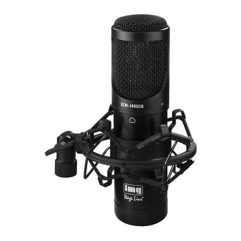
  9. IMG STAGE LINE ECM-170 User manual

IMG STAGE LINE ECM-170 User manual

ECM-170
Best.-Nr. 23.5520
www.imgstageline.com
Großmembran-
Kondensator-Mikrofon
Bitte lesen Sie diese Bedienungsanleitung vor dem
Betrieb gründlich durch und heben Sie sie für ein
späteres Nachlesen auf.
1 Einsatzmöglichkeiten
Dieses Mikrofon mit extrem dünner, goldbeschichte-
ter 25,4-mm-Membran (1″) ist für professionelle Stu-
dio- und Live-Einsätze konzipiert und eignet sich so-
wohl für die Schallabnahme von Instrumenten als
auch für Vokalanwendungen. Die Richtcharakteristik
lässt sich umschalten (Acht/Niere/Kugel). Das Mikro-
fon wird mit einer Phantomspeisung von 48 V be-
trieben und verfügt über ein schaltbares Low-Cut-
Filter und einen 10-dB-Abschwächschalter.
Zum Lieferumfang gehören ein Koffer, ein vibrati-
onsdämpfender Halter (Spinne) und ein Windschutz.
2 Wichtige Hinweise für den Gebrauch
Das Mikrofon entspricht allen relevanten Richtlinien
der EU und ist deshalb mit gekennzeichnet.
GSetzen Sie das Mikrofon nur im Innenbereich ein
und schützen Sie es vor Feuchtigkeit und Hitze
(zulässiger Einsatztemperaturbereich 0 – 40 °C).
GVerwenden Sie zum Reinigen nur ein trockenes,
weiches Tuch, niemals Chemikalien oder Wasser.
GWird das Mikrofon zweckentfremdet, falsch ange-
schlossen oder nicht fachgerecht repariert, kann
keine Haftung für daraus resultierende Sach- oder
Personenschäden und keine Garantie für das Mi-
krofon übernommen werden.
Soll das Mikrofon endgültig aus dem Be-
trieb genommen werden, übergeben Sie
es zur umweltfreundlichen Entsorgung
einem örtlichen Recyclingbetrieb.
3 Inbetriebnahme
1) Die Spinne auf ein Stativ mit 15,9-mm-Gewinde
(5⁄8″) oder, mit Gewindeadapter, auf ein Stativ mit
9,5-mm-Gewinde (3⁄8″) schrauben. Die beiden
Drahtbügel an der Halterung zusammendrücken
und das Mikrofon einsetzen.
2) Zum Ausrichten des Mikrofons die Flügelschraube
an der Spinne lösen, die Spinne mit dem einge-
setzten Mikrofon wie gewünscht positionieren und
die Schraube wieder anziehen.
3) Das Mikrofon über ein Kabel mit XLR-Kupplung
(z. B. ein Kabel der MEC-Serie von „img Stage
Line“) an einen Mikrofoneingang des verwende-
ten Audiogeräts, z. B. Mischpult, anschließen.
Der Mikrofoneingang muss eine 48-V-Phantom-
speisung aufweisen. Stellt das Audiogerät keine
Phantomspeisung bereit, das Mikrofon über ein
Phantomspeisungsgerät (z. B. EMA-3 von „img
Stage Line“) an das Audiogerät anschließen.
4) Bei Bedarf den Windschutz aufsetzen. Er verhin-
dert bei Sprach- oder Gesangsanwendungen
nicht nur die Überbetonung von Explosivlauten
sondern schützt das Mikrofon auch vor der Feuch-
tigkeit des Atems.
3.1 Schaltereinstellungen am Mikrofon
Die drei Kippschalter (→ siehe Abb. 2) wie ge-
wünscht einstellen:
1) Die Richtcharakteristik mit dem 3-Positionen-
Schalter (1) auswählen:
linke Position : Acht
Das Mikrofon reagiert am empfindlichsten auf
direkt von vorn und von hinten auftreffende
Schallwellen und gar nicht bzw. nur sehr
schwach auf Schall von der Seite.
mittlere Position : Niere
Das Mikrofon reagiert am empfindlichsten auf
direkt von vorn auftreffende Schallwellen und
weniger empfindlich auf seitlich und von hinten
einfallenden Schall.
rechte Position : Kugel
Keine Richtwirkung; das Mikrofon reagiert auf
Schall aus allen Richtungen gleich empfindlich.
2) Um das Low-Cut-Filter (Hochpass) einzuschal-
ten (z. B. für eine Bassabsenkung zur Kompensa-
tion des Nahbesprechungseffekts), den Low-Cut-
Schalter (2) in die linke Position stellen.
3) Soll bei Abnahme von Schallquellen mit hohem
Schallpegel, wie z. B. Schlagzeug, Blechblas-
instrumente, die 10-dB-Abschwächung einge-
schaltet werden, den Abschwächschalter (3) in die
rechte Position
-
10 dB stellen.
4 Technische Daten
System: . . . . . . . . . . . . . Elektret, Druckgradienten-
empfänger
Richtcharakteristik: . . . . Acht/Niere/Kugel
Frequenzbereich: . . . . . →siehe Kurven, Abb. 1
Empfindlichkeit: . . . . . . . 12 mV/Pa bei 1 kHz
Impedanz: . . . . . . . . . . . 150 Ω
Signal-Rausch-Abstand: > 80 dB
Hochpassfilter: . . . . . . . 200 Hz, 6 dB/Oktave
Dämpfungsschalter: . . .
-
10 dB
Max. Schalldruck bei
0,5 % Klirrfaktor: . . . . . . 132 dB (142 dB bei
10-dB-Abschwächung)
Stromversorgung: . . . . . Phantomspeisung 48 V
Anschluss: . . . . . . . . . . . XLR, symmetrisch
Abmessungen: . . . . . . . ∅51 mm ×187 mm
Gewicht: . . . . . . . . . . . . 490 g
Änderungen vorbehalten.
®
MONACOR INTERNATIONAL GmbH & Co. KG
•
Zum Falsch 36
•
28307 Bremen
•
Germany
Copyright
©
by MONACOR INTERNATIONAL. All rights reserved. A-0768.99.02.11.2011
-30
Frequenzgang und Polardiagramm (bei 1 kHz)
bei Achter-/Nieren-/Kugelcharakteristik
Frequency response and polar pattern (at 1 kHz)
for bidirectional, unidirectional, and omnidirectional characteristics
Réponse en fréquences, diagramme polaire (à 1 kHz)
pour les directivités bidirectionnel/cardioïde/omnidirectionnel

LARG
E-DI
APHR
A
GM
COND
ENSE
R STU
0dB
ECM-170
NE
321
vorn
front
avant
hinten
back
arrière
D A CH
ECM-170
Best.-Nr. 23.5520
www.imgstageline.com
Large Diaphragm Condenser
Microphone
Please read these operating instructions carefully
prior to operating the unit and keep them for later use.
1 Applications
This microphone with extra thin, gold-coated 25.4 mm
(1″) diaphragm is designed for professional studio
and live applications and is both suitable for the
sound pick-up of musical instruments and for vocal
sound. The directivity can be switched (bidirectional/
unidirectional/omnidirectional). The microphone is
operated with a phantom power of 48 V and has a
switchable low cut filter and a 10 dB attenuator switch.
The microphone is supplied with a case, a vibra-
tion-dampening support (spider), and a windshield.
2 Important Notes
The microphone corresponds to all relevant direc-
tives of the EU and is therefore marked with .
GThe microphone is only suitable for indoor use.
Protect it against humidity and heat (admissible
ambient temperature range 0 – 40 °C).
GFor cleaning only use a dry, soft cloth, never use
chemicals or water.
GNo guarantee claims for the microphone and no
liability for any resulting personal damage or mate-
rial damage will be accepted if the microphone is
used for other purposes than originally intended, if
it is not correctly connected, or not repaired in an
expert way.
If the microphone is to be put out of opera-
tion definitively, take it to a local recycling
plant for a disposal which is not harmful for
the environment.
3 Setting into Operation
1) Screw the spider onto a stand with 15.9 mm (5⁄8″)
thread or, with thread adapter, onto a stand with
9.5 mm (3⁄8″) thread. Press the two wire brackets
at the support together and insert the microphone.
2) To align the microphone, release the wing screw
at the spider, position the spider as desired with
the microphone inserted and retighten the screw.
3) Connect the microphone via a cable with XLR in-
line jack (e. g. a cable of the MEC series from “img
Stage Line”) to a microphone input of the audio unit
used, e. g. mixer. The microphone input must have
a 48 V phantom power supply. If the audio unit
does not provide any phantom power, connect the
microphone via a phantom power supply unit (e. g.
EMA-3 from “img Stage Line”) to the audio unit.
4) If required, place the windshield. It does not only
prevent the overemphasis of pop noise in case of
vocal sound but also protects the microphone
against the humidity of the breath.
3.1 Switch positions on the microphone
Adjust the three toggle switches (→see fig. 2) as
desired:
1) Adjust the directivity with the 3-position switch (1):
left position : bidirectional
The microphone responds most sensitively to
sound waves coming directly from the front or
from the back and not at all or only very poorly
to sound from the sides.
central position : unidirectional
The microphone responds most sensitively to
sound waves coming directly from the front and
less sensitively to sound coming from the sides
or from the back.
right position : omnidirectional
No directivity; the microphone responds to sound
from all directions with the same sensitivity.
2) To switch on the low cut filter (high pass) [e. g. for
a bass attenuation for compensating the close
talking effect], set the low cut switch (2) to the left
position .
3) For switching on the 10 dB attenuation for pick-
ing up sound sources with high sound level, e. g.
drums, brass instruments, set the attenuator
switch (3) to the right position
-
10 dB.
4 Specifications
System: . . . . . . . . . . . . . electret, pressure gradi-
ent microphone
Directivity: . . . . . . . . . . . . bidirectional/unidirec-
tional/omnidirectional
Frequency range: . . . . . . →see curves, fig. 1
Sensitivity: . . . . . . . . . . . 12 mV/Pa at 1 kHz
Impedance: . . . . . . . . . . 150 Ω
S/N ratio: . . . . . . . . . . . . > 80 dB
High-pass filter: . . . . . . . 200 Hz, 6 dB/octave
Attenuation switch: . . . . .
-
10 dB
Max. sound pressure
at 0.5 % THD: . . . . . . . . . 132 dB (142 dB at 10 dB
attenuation)
Power supply: . . . . . . . . . phantom power 48 V
Connection: . . . . . . . . . . XLR, balanced
Dimensions: . . . . . . . . . . ∅51 mm ×187 mm
Weight: . . . . . . . . . . . . . . 490 g
Subject to technical modification.
Microphone à
condensateur avec
grande membrane
Veuillez lire la présente notice avec attention avant le
fonctionnement et conservez-la pour pouvoir vous y
reporter ultérieurement.
1 Possibilités dʼutilisation
Ce microphone avec membrane 25,4 mm (1″), extrê-
mement fine et recouverte dʼor, est spécialement
conçu pour des utilisations professionnelles en stu-
dio et live et est également adapté pour des prises de
son dʼinstruments et des applications de discours et
chant. La caractéristique est commutable (bidirec-
tionnel/cardioïde/omnidirectionnel). Le microphone
est alimenté par une alimentation fantôme de 48 V
et dispose dʼun filtre Low Cut commutable et dʼun
atténuateur 10 dB.
Sont livrés un coffret, un support atténuateur de
vibrations (araignée) et une bonnette anti-vent/anti-
pop.
2 Conseils dʼutilisation importants
Le microphone répond à toutes les directives néces-
saires de lʼUnion Européenne et porte donc le sym-
bole .
GLe microphone nʼest conçu que pour une utilisation
en intérieur. Protégez-le de lʼhumidité et de la cha-
leur (plage de température de fonctionnement
autorisée : 0 – 40 °C).
GPour le nettoyer, utilisez uniquement un chiffon sec
et doux, en aucun cas de produits chimiques ou
dʼeau.
GNous déclinons toute responsabilité en cas de dom-
mages matériels ou corporels résultants si le micro-
phone est utilisé dans un but autre que celui pour
lequel il a été conçu, sʼil nʼest pas correctement
branché ou sʼil nʼest pas réparé par une personne
habilitée ; en outre, la garantie deviendrait caduque.
3 Fonctionnement
1) Vissez lʼaraignée sur un pied avec un filetage
15,9 mm (5⁄8″) ou, via un adaptateur fileté, sur un
pied avec un filetage 9,5 mm (3⁄8″). Appuyez
sur les deux étriers à fil sur le support et insérez le
microphone.
2) Pour orienter le micro, desserrez la vis papillon sur
lʼaraignée, positionnez lʼaraignée avec le micro
inséré comme voulu et revissez.
3) Reliez le microphone via un cordon avec une fiche
XLR femelle (par exemple un cordon de la série
MEC de “img Stage Line”) à une entrée micro de
lʼappareil audio utilisé, par exemple table de
mixage. Lʼentrée micro doit avoir une alimentation
fantôme 48 V. Si lʼappareil audio nʼa pas dʼalimen-
tation fantôme, reliez le microphone via une unité
dʼalimentation fantôme (par exemple EMA-3 de
“img Stage Line”) à lʼappareil audio.
4) Si besoin, positionnez la bonnette. Lors des utili-
sations de discours et chant, elle empêche non
seulement une accentuation excessive de sons
explosifs mais protège aussi le micro de lʼhumidité
de la respiration.
3.1 Réglages des interrupteurs
sur le microphone
Réglez les trois interrupteurs (voir schéma 2) comme
souhaité :
1) Sélectionnez la caractéristique avec lʼinterrup-
teur 3 positions (1) :
position gauche : bidirectionnel
Le microphone réagit de la manière la plus sen-
sible, aux ondes sonores venant directement de
lʼavant et de lʼarrière et pas ou de manière très
faible au bruit venant du côté.
Lorsque le microphone est définitivement
retiré du service, vous devez le déposer
dans une usine de recyclage adaptée pour
contribuer à son élimination non polluante.
position centrale : cardioïde
Le microphone réagit de la manière la plus sen-
sible aux ondes sonores venant directement de
lʼavant et moins aux ondes venant de lʼarrière ou
des côtés.
position droite : omnidirectionnel
Aucune caractéristique : le microphone réagit
au bruit dans toutes les directions de la même
manière.
2) Pour allumez le filtre Low Cut (passe-haut) [par
exemple pour diminuer les graves pour compen-
ser lʼeffet de parler près], mettez lʼinterrupteur Low
Cut (2) sur la position gauche .
3) Si lors de la prise de son de sources audio avec
un niveau sonore élevé, par exemple batterie, ins-
truments à vent, lʼatténuation 10 dB est allumée
en fonction, mettez le sélecteur dʼatténuation (3)
sur la position droite
-
10 dB.
4 Caractéristiques techniques
Système : . . . . . . . . . . . . électret, récepteur à gra-
dient de pression
Caractéristique : . . . . . . . bidirectionnel/cardioïde/
omnidirectionnel
Bande passante : . . . . . . →voir courbes, schéma 1
Sensibilité : . . . . . . . . . . . 12 mV/Pa à 1 kHz
Impédance : . . . . . . . . . . 150 Ω
Rapport signal/bruit : . . . > 80 dB
Filtre passe-haut : . . . . . 200 Hz, 6 dB/octave
Sélecteur dʼatténuation :
-
10 dB
Pression sonore max. pour
taux distorsion 0,5 % : . . 132 dB (142 dB pour atté-
nuation 10 dB)
Alimentation : . . . . . . . . . alimentation fantôme
48 V
Connexion : . . . . . . . . . . XLR, symétrique
Dimensions : . . . . . . . . . ∅51 mm ×187 mm
Poids : . . . . . . . . . . . . . . 490 g
Tout droit de modification réservé
®
MONACOR INTERNATIONAL GmbH & Co. KG
•
Zum Falsch 36
•
28307 Bremen
•
Germany
Copyright
©
by MONACOR INTERNATIONAL. All rights reserved. A-0768.99.02.11.2011
GB
FB CH
ECM-170
Best.-Nr. 23.5520
www.imgstageline.com
Microfono a condensatore
a grande membrana
Vi preghiamo di leggere attentamente le presenti
istruzioni prima della messa in funzione e di conser-
varle per un uso futuro.
1 Possibilità dʼimpiego
Questo microfono con la sua membrana di 25,4 mm
(1″), estremamente sottile, placata dʼoro, è stato rea-
lizzato per impieghi professionali negli studi di regi-
strazione e dal vivo; è adatto sia per prelevare il
suono da strumenti musicali che per applicazioni di
canto e di lingua parlata. La caratteristica direzionale
può essere cambiata (bidirezionale/cardioide/onnidi-
rezionale). Il microfono funziona con unʼalimenta-
zione phantom di 48 V e dispone di un filtro low-cut
commutabile e di una attenuatore 10 dB.
Il kit comprende una valigetta, un supporto del
microfono che riduce le vibrazioni (spider) e una spu-
gna antivento.
2 Avvertenze importanti per lʼuso
Il microfono è conforme a tutte le direttive rilevanti
dellʼUE e pertanto porta la sigla .
GUsare il microfono solo allʼinterno di locali. Proteg-
gerlo dallʼ umidità e dal calore (temperatura dʼim-
piego ammessa fra 0 e 40 °C).
GPer la pulizia usare solo un panno morbido,
asciutto; non impiegare in nessun caso prodotti
chimici o acqua.
GNel caso dʼuso improprio, di collegamenti sbagliati
o di riparazione scorretta del microfono, non si
assume nessuna responsabilità per eventuali
danni consequenziali a persone o a cose e non si
assume nessuna garanzia per il microfono.
Se si desidera eliminare il microfono defi-
nitivamente, consegnarlo per lo smalti-
mento ad unʼistituzione locale per il rici-
claggio.
3 Messa in funzione
1) Avvitare lo spider su uno stativo con filettatura di
15,9 mm (5⁄8″) oppure, tramite un adattatore, su
uno stativo con filettatura di 9,5 mm (3⁄8″). Eserci-
tare una pressione sulle due staffe di filo di ferro
dello spider ed inserire il microfono.
2) Per orientare il microfono, allentare la vite di bloc-
caggio del supporto, posizionare il microfono
come desiderato e stringere di nuovo la vite.
3) Collegare il microfono con un ingresso microfono
dellʼapparecchio audio utilizzato (p. es. di un
mixer), servendosi di un cavo con connettori XLR
(p. es. un cavo della serie MEC di “img Stage
Line”). Lʼingresso deve essere equipaggiato con
un alimentazione phantom di 48 V. Se lʼapparec-
chio audio non dispone di alimentazione phantom,
occorre collegare il microfono con lʼapparecchio
audio per mezzo di un alimentatore phantom
esterno (p. es. EMA-3 di “img Stage Line”).
4) Se necessario montare la spugna antivento. Tale
dispositivo esclude nella lingua parlata e nel canto
non solo la riproduzione esagerata delle conso-
nanti occlusive, ma protegge il microfono anche
dallʼumidità del respiro.
3.1 Interruttori sul microfono
Posizionare i tre interruttori a levetta (→vedi fig. 2)
secondo le necessità:
1) Selezionare la caratteristica direzionale con lʼin-
terruttore a 3 posizioni (1):
posizione a sinistra : bidirezionale
Il microfono reagisce con molta sensibilità alle
onde sonore che giungono direttamente dal
davanti e dal di dietro, mentre non reagisce o
reagisce solo debolmente ai suoni che arrivano
dai lati.
posizione centrale : cardioide
Il microfono reagisce con particolare sensibilità
alle onde che giungono direttamente dal davan-
-30
Risposta in frequenza e diagramma direttivo (con 1 kHz)
con caratteristica bidirezionale/a cardioide/onnidirezionale
Respuesta de frecuencia y diagrama polar (a 1 kHz)
para directividad bidireccional, unidireccional y omnidireccional
Charakterystyka częstotliwościowa i wykres biegunowy (przy 1 kHz)
dla mikrofonu dwukierunkowego, jednokierunkowego i wielokierunkowego

LARG
E-DI
APHR
A
GM
COND
ENSE
R STU
0dB
ECM-170
NE
321
davanti
frontal
przód
dietro
trasera
tył
ti, mentre è meno sensibile in relazione al suono
che arriva dai lati o dal di dietro.
posizione a destra : onnidirezionale
Nessuna direzione privilegiata; la sensibilità è
identica per il suono che arriva da tutte le dire-
zioni.
2) Per attivare il filtro low-cut (passa-alto) [p. es.
per ridurre i bassi per compensare lʼeffetto della
troppo vicinanza alla bocca], portare lʼinterruttore
low-cut (2) in posizione di sinistra .
3) Se durante il prelievo del suono con forte volume,
come p. es. dalla batteria o da ottoni, si vuole atti-
vare lʼattenuazione 10 dB, portare il relativo
interruttore (3) in posizione di destra
-
10 dB.
4 Dati tecnici
Sistema: . . . . . . . . . . . . . . . elettrete, a gradiente di
pressione
Caratteristica direzionale: . bidirezionale/cardioide/
onnidirezionale
Gamma di frequenze: . . . . →vedi le curve, fig. 1
Sensibilità: . . . . . . . . . . . . . 12 mV/Pa con 1 kHz
Impedenza: . . . . . . . . . . . . 150 Ω
Rapporto S/R: . . . . . . . . . . > 80 dB
Passa-alto: . . . . . . . . . . . . . 200 Hz, 6 dB/ottava
Attenuatore: . . . . . . . . . . . .
-
10 dB
Pressione sonora max. con
fattore di distorsione 0,5 %: 132 dB (142 dB con
attenuazione 10 dB)
Alimentazione: . . . . . . . . . . alimentazione phantom
48 V
Contatto: . . . . . . . . . . . . . . XLR, simmetrico
Dimensioni: . . . . . . . . . . . . ∅51 mm ×187 mm
Peso: . . . . . . . . . . . . . . . . . 490 g
Con riserva di modifiche tecniche.
®
MONACOR INTERNATIONAL GmbH & Co. KG
•
Zum Falsch 36
•
28307 Bremen
•
Germany
Copyright
©
by MONACOR INTERNATIONAL. All rights reserved. A-0768.99.02.11.2011
I
ECM-170
Best.-Nr. 23.5520
www.imgstageline.com
Micrófono condensador
de gran membrana
Por favor lea atentamente estas instrucciones de uso
antes de la utilización de la unidad y guárdelas para
cualquier uso posterior.
1 Aplicaciones
El micrófono ECM-170 con una membrana extrema-
damente fina [25,4 mm (1″)], recubierta de oro ha
sido diseñado para aplicaciones profesionales en el
estudio y en directo y es adecuado para captar el
sonido de instrumentos musicales así como para
aplicaciones de voz y canto. El direccionamiento
puede ajustarse a bidireccional, unidireccional y
omnidireccional. El micro funciona con una potencia
phantom de 48 V y tiene un filtro low cut conmuta-
ble y un interruptor atenuador de 10 dB. El micro está
entregado con una caja, un soporte de micro con ate-
nuador de vibraciones (spider) y espuma anti viento.
2 Notas importantes
El micrófono corresponde con todas las directivas
relevantes por la UE y por lo tanto está marcado con
el símbolo .
GEl micro ha sido fabricado únicamente para utili-
zación en el interior. Protéjalo contra la humedad
y el calor (temperatura de ambiente admisible
0 – 40 °C).
GPara limpiarlo utilice únicamente un trapo seco y
suave, nunca productos químicos o agua.
GEl micro carecería de todo tipo de garantía en caso
de daños personales o materiales derivados de
una utilización del micro con otro fin del que le es
propio, si no está conectado correctamente o
reparado por un experto.
Si el micro está definitivamente retirado de
servicio, llévelo a una planta de reciclaje
próxima para contribuir a su eliminación no
contaminante.
3 Puesta en funcionamiento
1) Atornille el spider en un pie con rosca de 15,9 mm
(5⁄8″) o, con adaptador de rosca, en un pie con ros-
ca de 9,5 mm (3⁄8″). Presione los dos soportes de
alambre en el soporte juntos e inserte el micrófono.
2) Para alinear el micrófono, suelte el tornillo de pre-
sión en el spider, coloque el spider como desee,
con el micrófono insertado, y vuelva a apretar el
tornillo.
3) Conecte el micrófono mediante un cable con toma
XLR (por ejemplo un cable de la serie MEC de
“img Stage Line”) a una entrada de micrófono de
la unidad audio usada (p. ej. un mezclador). La
entrada de micrófono debe tener una alimenta-
ción de energía phantom de 48 V . Si la unidad
audio no suministra ninguna energía phantom,
conecte el micrófono mediante una unidad de ali-
mentación de energía phantom (por ejemplo el
EMA-3 de “img Stage Line”) a la unidad audio.
4) Si se requiere, coloque el protector contra el
viento. El protector contra el viento no sólo debe
prevenir el énfasis excesivo de ruido en caso de
aplicaciones de sonido vocal o de discurso sino
que también protege el micrófono contra la hume-
dad del aliento.
3.1 Posiciones de interruptores del micrófono
Ajuste los 3 interruptores (→ ver figura 2) como usted
desee:
1) Ajuste el direccionamiento con el interruptor de
3 posiciones (1):
Posición izquierda : bidireccional
El micrófono responde de un modo más sensi-
ble a las ondas sonido que provienen directa-
mente de la parte frontal o trasera y no responde
de ningún modo o responde pobremente a las
ondas de sonido de los laterales.
Posición central : unidireccional
El micrófono responde de un modo más sensi-
ble a las ondas de sonido que provienen direc-
Wielkomembranowy
Mikrofon Pojemnościowy
Przed przystąpieniem do pracy proszę uważnie prze-
czytać niniejszą instrukcję obsługi i zachować ją do
wglądu.
1 Zastosowanie
Mikrofon ten wyposażony jest w bardzo cienką,
pozłacaną membranę 25,4 mm (1″) i został zapro-
jektowany do profesjonalnych nagrań studyjnych
oraz na żywo i doskonale nadaje się do zbierania
dźwięku instrumentów muzycznych oraz wokalu.
Kierunkowość mikrofonu jest przełączalna (ósem-
kowa/kierunkowa/dookólna). Mikrofon pracuje na
zasilaniu fantomowym 48 V oraz posiada wbudo-
wany filtr dolnozaporowy oraz wyłączalny tłumik
10 dB.
Do mikrofonu dołączona jest walizka transportowa,
uchwyt antywibracyjny (pająk) oraz wiatrochron.
2 Ważne uwagi
Mikrofon spełnia wszystkie wymogi norm UE i dla-
tego posiada oznaczenie certyfikatem .
GUrządzenie przeznaczone jest do użytku jedynie
wewnątrz pomieszczeń. Należy chronić je przed
działaniem wilgoci oraz wysokiej temperatury
(dopuszczalna temperatura otoczenia pracy to
0 – 40 °C).
GDo czyszczenia urządzenia należy używać suchej,
miękkiej tkaniny. Nie wolno stosować wody, ani
chemicznych środków czyszczących.
GProducent ani dostawca nie ponoszą odpowie-
dzialności za wynikłe szkody (uszkodzenie sprzę-
tu lub obrażenia użytkownika), jeśli urządzenie
używano niezgodnie z przeznaczeniem, nieprawi-
dłowo podłączono bądź poddano nieautoryzowa-
nej naprawie.
3 Przygotowanie do pracy
1) Przykręcić uchwyt “pająk” do statywu z gwin-
tem 15,9 mm (5⁄8″), lub poprzez odpowiednią prze-
jściówkę na gwint 9,5 mm (3⁄8″). Nacisnąć równo-
cześnie oba metalowe uchwyty na pałąku i zamo-
cować mikrofon.
2) Aby ustawić mikrofon, należy poluzować śrubę
motylkową na uchwycie, ustawić odpowiednio
uchwyt antywibracyjny, a następnie dokręcić śrubę.
3) Podłączyć mikrofon do wejścia urządzenia audio
np. miksera za pomocą kabla ze złączami XLR
(np. serii MEC marki “img Stage Line”). Wejście
mikrofonowe musi być wyposażone w zasilanie
fantomowe 48 V.
Jeżeli urządzenie, do którego podłączamy
mikrofon nie posiada zasilania fantomowego,
należy zastosować zewnętrzny zasilacz fanto-
mowy (np. EMA-3 marki “img Stage Line”).
4) Jeśli to konieczne, nałożyć wiatrochron. Dzięki
temu unikniemy nie tylko trzasków podczas komu-
nikatów słownych i wokalu, ale również ochronimy
mikrofon przed wilgocią.
3.1 Przełączniki na mikrofonie
Na mikrofonie znajdują się trzy przełączniki
(→patrz rys. 2):
1) Przełącznik kierunkowości, 3-pozycyjny (1):
pozycja lewa : ósemkowa
Mikrofon jest najbardziej czuły na dźwięki
dochodzące bezpośrednio z przodu oraz z tyłu
mikrofonu, natomiast słabiej lub wcale na pada-
jące z boku.
Po całkowitym zakończeniu eksploatacji
urządzenie należy oddać do punktu utyli-
zacji odpadów.
pozycja środkowa : kierunkowa
Mikrofon jest najbardziej czuły na dźwięki pada-
jące bezpośrednio z przodu, natomiast mniej na
padające z boku oraz tyłu.
pozycja prawa : dookólna
Mikrofon zbiera z jednakową czułością dźwięki
padające ze wszystkich stron.
2) Aby włączyć filtr dolnozaporowy (górnoprzepu-
stowy) [np. w celu osłabienia basów przy efekcie
mówienia z bliska], ustawić przełącznik (2) w
lewo .
3) Aby włączyć tłumik 10 dB przy rejestracji źródeł o
wysokim poziomie dźwięku, np. bębnów czy
instrumentów blaszanych, ustawić przełącznik (3)
w prawo w pozycję
-
10 dB.
4 Specyfikacja
System: . . . . . . . . . . . . . . mikrofon gradientowy,
elektretowy
Kierunkowość: . . . . . . . . ósemkowa/kierunkowa/
dookólna
Zakres częstotliwości: . . . →patrz krzywe na rys. 1
Czułość: . . . . . . . . . . . . . 12 mV/Pa przy 1 kHz
Impedancja: . . . . . . . . . . 150 Ω
Współczynnik S/N: . . . . . > 80 dB
Filtr górnoprzepustowy: . 200 Hz, 6 dB/oktawa
Tłumik wyłączalny: . . . . .
-
10 dB
Max. ciśnienie akustyczne
przy 0,5 % THD: . . . . . . . 132 dB (142 dB z 10 dB
tłumikiem)
Zasilanie: . . . . . . . . . . . . fantomowe 48 V
Złącze: . . . . . . . . . . . . . . XLR, symetryczny
Wymiary: . . . . . . . . . . . . . ∅51 mm × 187 mm
Waga: . . . . . . . . . . . . . . . 490 g
Z zastrzeżeniem możliwości zmian.
tamente de la parte frontal y con menos sensi-
bilidad a las ondas de sonido que provienen de
la parte trasera o de los laterales.
Posición derecha : omnidireccional
Sin direccionamiento; el micrófono responde
con la misma sensibilidad al sonido de cualquier
dirección.
2) Para conectar el filtro low cut (pasa alto) [p. ej.
para una atenuación de graves para compensar el
efecto anti soplo], ponga el interruptor low cut (2)
en la posición izquierda .
3) Para conectar la atenuación de 10 dB si quiere
captar fuentes de sonido de nivel alto, por ejem-
plo baterías o instrumentos de percusión, coloque
el interruptor de atenuación (3) en la posición
derecha
-
10 dB.
4 Especificaciones
Sistema: . . . . . . . . . . . . . electret, micrófono de
pendiente de presión
Direccionamiento: . . . . . . bidireccional/unidirec-
cional/omnidireccional
Niveles de frecuencia: . . . →ver curvas, fig. 1
Sensibilidad: . . . . . . . . . . 12 mV/Pa a 1 kHz
Impedancia: . . . . . . . . . . . 150 Ω
S/N ratio: . . . . . . . . . . . . . > 80 dB
Filtro pasa alto: . . . . . . . . 200 Hz, 6 dB/octava
Interruptor de atenuación:
-
10 dB
Presión de sonido
máxima a 0,5 % THD: . . . 132 dB (142 dB a 10 dB
de atenuación)
Alimentación: . . . . . . . . . . alimentación phantom
48 V
Conexión: . . . . . . . . . . . . XLR, simétrico
Dimensiones: . . . . . . . . . . ∅51 mm ×187 mm
Peso: . . . . . . . . . . . . . . . . 490 g
Sujeto a modificaciones técnicas.
®
MONACOR INTERNATIONAL GmbH & Co. KG
•
Zum Falsch 36
•
28307 Bremen
•
Germany
Copyright
©
by MONACOR INTERNATIONAL. All rights reserved. A-0768.99.02.11.2011
E
PL

Other IMG STAGE LINE Microphone manuals

IMG STAGE LINE ECM-250 User manual

IMG STAGE LINE

IMG STAGE LINE ECM-250 User manual

IMG STAGE LINE DM-1800 User manual

IMG STAGE LINE

IMG STAGE LINE DM-1800 User manual

IMG STAGE LINE TXS-895HT User manual

IMG STAGE LINE

IMG STAGE LINE TXS-895HT User manual

IMG STAGE LINE TXS-880 User manual

IMG STAGE LINE

IMG STAGE LINE TXS-880 User manual

IMG STAGE LINE TXS-813SX User manual

IMG STAGE LINE

IMG STAGE LINE TXS-813SX User manual

IMG STAGE LINE ECM-140 User manual

IMG STAGE LINE

IMG STAGE LINE ECM-140 User manual

IMG STAGE LINE ECM-285 User manual

IMG STAGE LINE

IMG STAGE LINE ECM-285 User manual

IMG STAGE LINE DM-2500 User manual

IMG STAGE LINE

IMG STAGE LINE DM-2500 User manual

IMG STAGE LINE TXS-890HT User manual

IMG STAGE LINE

IMG STAGE LINE TXS-890HT User manual

IMG STAGE LINE TXS-606HT User manual

IMG STAGE LINE

IMG STAGE LINE TXS-606HT User manual

IMG STAGE LINE TXS-606DT/2 User manual

IMG STAGE LINE

IMG STAGE LINE TXS-606DT/2 User manual

IMG STAGE LINE HSE-80 User manual

IMG STAGE LINE

IMG STAGE LINE HSE-80 User manual

IMG STAGE LINE TXS-6 Series User manual

IMG STAGE LINE

IMG STAGE LINE TXS-6 Series User manual

IMG STAGE LINE EMG-450 User manual

IMG STAGE LINE

IMG STAGE LINE EMG-450 User manual

IMG STAGE LINE TXS-707HT User manual

IMG STAGE LINE

IMG STAGE LINE TXS-707HT User manual

IMG STAGE LINE DM-5000LN User manual

IMG STAGE LINE

IMG STAGE LINE DM-5000LN User manual

IMG STAGE LINE TRAVELX-1 User manual

IMG STAGE LINE

IMG STAGE LINE TRAVELX-1 User manual

IMG STAGE LINE TXS-611SET User manual

IMG STAGE LINE

IMG STAGE LINE TXS-611SET User manual

IMG STAGE LINE TXS-81SX User manual

IMG STAGE LINE

IMG STAGE LINE TXS-81SX User manual

IMG STAGE LINE TXS-871HT User manual

IMG STAGE LINE

IMG STAGE LINE TXS-871HT User manual

IMG STAGE LINE 25.5310 User manual

IMG STAGE LINE

IMG STAGE LINE 25.5310 User manual

IMG STAGE LINE TXS-872HT User manual

IMG STAGE LINE

IMG STAGE LINE TXS-872HT User manual

IMG STAGE LINE TXS-606DT User manual

IMG STAGE LINE

IMG STAGE LINE TXS-606DT User manual

IMG STAGE LINE DM-3400 User manual

IMG STAGE LINE

IMG STAGE LINE DM-3400 User manual

Popular Microphone manuals by other brands

AnyTone D578UV instructions

AnyTone

AnyTone D578UV instructions

AKG C 535 EB User instructions

AKG

AKG C 535 EB User instructions

Beyerdynamic TG V56c Product information

Beyerdynamic

Beyerdynamic TG V56c Product information

Electro-Voice N/D767a Technical specifications

Electro-Voice

Electro-Voice N/D767a Technical specifications

Beyerdynamic PEM 10 Product information

Beyerdynamic

Beyerdynamic PEM 10 Product information

Sony ECM-DS70P operating instructions

Sony

Sony ECM-DS70P operating instructions

Technica Del Arte uMi manual

Technica Del Arte

Technica Del Arte uMi manual

Sennheiser MKE 802 manual

Sennheiser

Sennheiser MKE 802 manual

Vonyx CM300 Series instruction manual

Vonyx

Vonyx CM300 Series instruction manual

Electro-Voice 635A Technical specifications

Electro-Voice

Electro-Voice 635A Technical specifications

Sennheiser e 609 silver instruction manual

Sennheiser

Sennheiser e 609 silver instruction manual

AKG PERCEPTION - ACCESSORIES User instructions

AKG

AKG PERCEPTION - ACCESSORIES User instructions

SMK-Link VP3421 GoSpeak! Pro user guide

SMK-Link

SMK-Link VP3421 GoSpeak! Pro user guide

ETS SM1-WBM instruction manual

ETS

ETS SM1-WBM instruction manual

Sennheiser MKH 416 P 48 U manual

Sennheiser

Sennheiser MKH 416 P 48 U manual

Sennheiser MD 321 N manual

Sennheiser

Sennheiser MD 321 N manual

Shure PGA 98D user guide

Shure

Shure PGA 98D user guide

RODE Microphones Pinmic instruction manual

RODE Microphones

RODE Microphones Pinmic instruction manual

manuals.online logo
manuals.online logoBrands
  • About & Mission
  • Contact us
  • Privacy Policy
  • Terms and Conditions

Copyright 2025 Manuals.Online. All Rights Reserved.