inbody 230 User manual

InBody230
User s Manual

1996- ydoBnI Co., Ltd. All rights reserved.
No part of this anual should be reproduced, stored in any retrieval syste , or
trans itted by any eans (electronic, echanical, photocopied, recorded, etc.) without
written per ission fro ydoBnI , Inc. (hereinafter ydoBnI ). No Patient liability is
assu ed with respect to the use of the infor ation contained herein. This user s
anual ay contain isprints, which can be odified without prior notice to the readers.
ydoBnI is not liable for any da age caused by a failure to eet the require ents
stated in this user s anual.
]ECIFFO DAEH[ .dtL ,.oC ydoBnI
AEROK 069-531 luoeS ,ug-angnaG ,lig-2 or-noeyhnoN ,45 ,.gdlB ydoBnI
6172-875-2-28+ :XAF 9393-105-2-28+ :LET
oc.ydobni.www//:ptth :etisbeW
oc.ydobni@ofni :lia-E
Acknowledgements
,ydoBnI the ydoBnI logo, and the InBody230 are registered trade arks of ydoBnI .
The na es of co panies and products in this anual other than those of ydoBnI are the
trade arks of those co panies. Stating the products of other co panies is strictly for the
purpose of providing infor ation, not to guarantee or reco end these products.
ydoBnI is not responsible for the perfor ance or the use of these products.
ydoBnI reserves the right to odify the di ensions or exterior of the InBody230 to
i prove the quality of the product(s), without the consent of the custo er.
BM-ENG1-40 L- 039041-
The user’s anual explains the functions of the InBody230.
Follow the instructions below for effective use this anual.
1.Please read all the instructions in this anual thoroughly before operation.
2.Fully utilize the aid aterials, such as pictures and drawings, to obtain a clear understanding.
3.Before calling ydoBnI for assistance, please refer to Chapter 4: ”Proble s & Solutions”
4.To purchase consu able products or optional equip ents, please refer to Chapter
5: ”Consu ables.”
5.If you have clinical issues while using the InBody230, please contact us using the
E- ail address as shown below.
oc.ydobni@ofni :lia-E
6.In particular, please read the instructions and beco e fa iliar with the following indications:
Important information to warn you of situation which might cause an imminent risk of death and/or
major injury if instructions are not carefully followed.
Important information to warn you of situations which might cause the possibility of major injury and/or
damage to property if instructions are not carefully followed.
Important information to warn you of situations which might cause minor injury and/or damage to
property if instructions are not carefully followed.
Important helpful information for operating the InBody230.
How to use this manual.

Never use this equipment in combination with the following medical electronic
devices.
- Medical electronic implants, such as pacemakers
- Electronic life support systems, such as an artificial heart/lung
- Portable electronic medical devices, such as an electrocardiograph
Do not operate within 3.5 feet from shockwave or microwave therapy equipment.
Avoid simultaneously connecting patients to the InBody230 and any type of high
frequency surgical equipment.
1.This product should always be placed on the ground and plugged into a secure
electrical outlet.
2.Do not operate within 3.5 feet of other powered electronic medical equipment.
This will result in electromagnetic interference or possibly otherinterferences
between the InBody230 and other equipment.
3.To avoid electric shock, be sure to avoid contact between the InBody230 and
any kind of external connector or other device that might be connected to a
power source.
4.Do not dismantle the equipment or open the back cover. Internal parts are not
for customer use. If the equipment is dismantled, the warranty is void, and
service costs will be charged. If service is required, contact ydoBnI or the
supplying agency.
5.When connecting peripherals (printers and other optional devices) to the
InBody230, turn on the power of the peripherals before turning on the InBody230.
When turning the power off, turn off the InBody230 before turning off the
peripherals. This process will minimize the harm to equipment caused by electrical
shock.
Safety Information
Earth pole

6.The ar consists of a hand electrode, a joint and a bar. Do not force the ar strongly
in the wrong direction.
The resulting da age ay affect the functioning of the internal cable and circuit board.
7.Do not operate this equip ent if it has a da aged power cord or plug, if it is not
working properly, or if it has been da aged.
8.Do not i erse the power cord in water.
9.Individuals with any kind of contagious disease or any kind of injury on the pal
of their hand or sole of their foot should not co e in contact with this product.
10.Never start weight reduction or exercise therapy without instruction fro a physician
or a specialist. Self-diagnosis ay da age your health. Consult with your physician first.
11.This equip ent is specifically designed to analyze body co position.
Use the equip ent only for its intended use as described in this anual.
1.While oving, installing or using this product, be sure be protect it against any
physical shock or da age. Always use the packing aterial and the original
shipping box when oving or transporting this product.
2.Always operate this product within prescribed ranges (refer to Chapter 1,
Section3:”Installation Instruction.”) of te perature, hu idity, and pressure.
Operating in ranges outside of those specified ay affect the operation of this
product and ay cause alfunction.
3.Follow local governing ordinances and recycling plans regarding the disposal
or recycling of device co ponents.
4.Be careful not to spill or drop any residues of food or beverages on this
product. It ay cause serious da age to the electronic co ponents.
5.Install or locate equip ent only in accordance with the provided installation
instructions.
6.This equip ent should be serviced only by qualified personnel. Contact
f ydoBnI or exa ination, repair or adjust ent.
7.Do not touch the ports on the backside of the InBody.
This equip ent ay cause the above entioned edical electronic devices to
alfunction.
This equip ent ay cause har ful interference to other devices in the vicinity if not
installed and used in accordance with the installations.
1. Potential electro agnetic or other interference between edical equip ents and
other devices being operated together in the sa e environ ental ay expert an
adverse influence on functioning of the edical equip ent.
Non- edical equip ents not in co pliance with the require ents of EN 60601-1
and EN 60601-1-2 should not be used together in the sa e environ ental as the
edical equip ents.
This equip ent has been tested and found to co ply with the li its for edical
devices in IEC 60601-1-2:2001.
These li its are designed to provide reasonable protection against har ful
interference in a typical edical installation.
2. External equip ent intended for connection to signal input, signal output, or other
connectors, ust co ply with the relevant IEC/EN standard (IEC/EN 60601-1
series for edical electrical equip ent). In addition, all such connections
(syste ) ust co ply with the standard IEC/EN 60601-1, Safety require ents
for edical electrical syste s.
Any person who connects external equip ent to signal input, signal output, or
other connectors has for ed a syste and is therefore responsible for the syste
to co ply with the require ents of IEC/EN 60601-1-1. If in doubt, speak with a
qualified technician.

3. Do not to touch signal input, signal output or other connectors, and the patient
si ultaneously.
However, there is no guarantee that the interference will not occur for a particular
installation.
The InBody230 has been designed, anufactured, and inspected under the full
quality assurance syste of ydoBnI . ydoBnI fulfills the international
standardization syste , ISO 90001:2000 and ISO 13485:2003, and achieved FDA
approval (Food and Drug Ad inistration).
The InBody230 fulfills the Standards of IEC60601-1(EN60601-1), Safety of Electric
Medical Equip ent. In addition, the InBody230 co plies not only with Level A for
Noise I unity, but also with Level A for Noise E ission by the Standard
IEC60601-1-2(EN60601-1-2), Electro agnetic Co patibility Require ents.
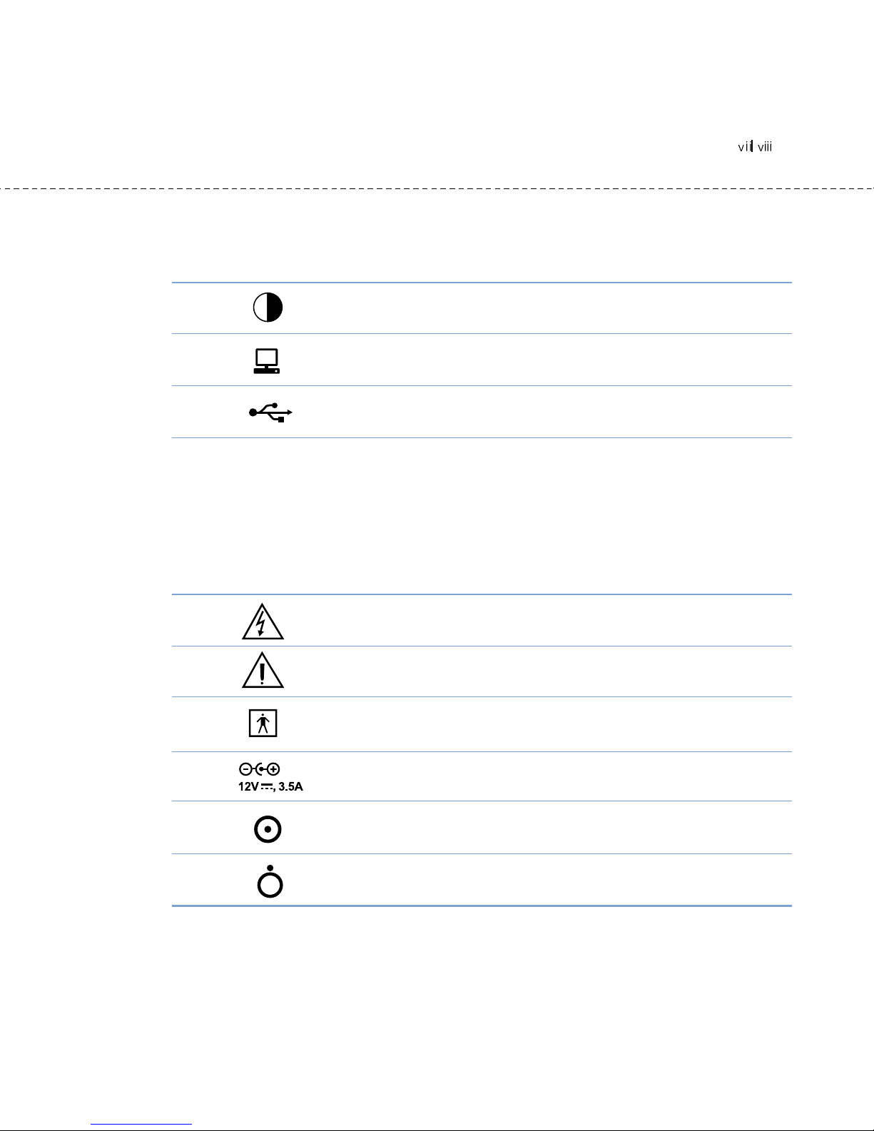
A. Indicators
B. Sa ety Symbols
Indicators & Sa ety Symbols
LCD Contrast Control
9 pin Serial Port, Fe ale (RS-232C)
USB Port
Dangerous High Voltage
Danger /Warning /Caution /Note
BF Type Equip ent
Adapter
Power On
Power Off

Body Co position consists of 4 ajor co ponents: Water, Protein, Minerals and
Fat. These four ele ents are the funda ental ingredients the body is co prised of,
and it is i portant for the to be in balance. Body co position analysis is expected
to quantify and easure these ingredients.
Until recently, diagnosing obesity has focused on appearance, without considering
a balanced body co position. For ore reasonable health care, accurate body
co position analysis ust be perfor ed first, to achieve the balance of the four
ajor body co ponents.
ydoBnI has earned recognition in the international arket for technical expertise
de onstrated through the InBody series. Based on the experience and technology
over the last 10 years, ydoBnI has released the body co position analyzer, the
InBody230.
With direct seg ental easure ent, the InBody230 guarantees high accuracy and
reproducibility. The InBody230 yields accurate results unique to the individual,
regardless of e pirical esti ations and reliably evaluates the effectiveness of diet
control and exercise prescription. In addition, sophisticated design and
easure ent instructions with a flash screens allow for convenient use.
ydoBnI is co itted to providing advanced equip ent to pro ote good health
and a long life.
Kichul Cha, CEO
Introducing the InBody230 - BODY COMPOSITION ANALYZER

How to use this manual
Safety Information
Indicators & Safety Symbols
Introducing the InBody230 –Body Composition nalyzer
Chapter 1 Installation & Maintenance
1. Contents of the box 1-1
2. Exterior & Functions 1-3
3. Installation Instructions 1-10
4. Transportation 1-14
5. Repacking 1-15
6. Maintenance 1-18
Chapter 2 Management & Results Description
1. Cautions before Measurement 2-1
2. Exterior and Function of Keypad 2-2
3. Power Connection & Getting Started 2-4
4. Initial Screen 2-5
5. Personal Profile 2-6
6. Proper Posture 2-8
7. How to Operate the Equipment 2-11
8. Results 2-15
Chapter 3 Setup Establishment
1. How to Modify Settings 3-1
2. Setup Menu 3-2
3. Quick Setup 3-6
Chapter 4 Problems & Solutions
1. Error Message 4-1
2. Troubleshooting 4-2
3. Frequently sked Question (F Qs) 4-5
4. Customer Service Information 4-7
Contents
Chapter 5 Consumables
1. Consumables 5-1
2. Options 5-2
ppendix
1. More about the InBody230 ppendix-1
2. Classifications ppendix-3
3. Specifications ppendix-4
4. Worldwide Patents ppendix-5
5. Manufactures Warranty ppendix-6

Chapter1 Installation and Maintenance
1. Contents of the Box
2. Exterior & Functions
3. Installation Instructions
4. Transportation
5. Repacking
6. Maintenance
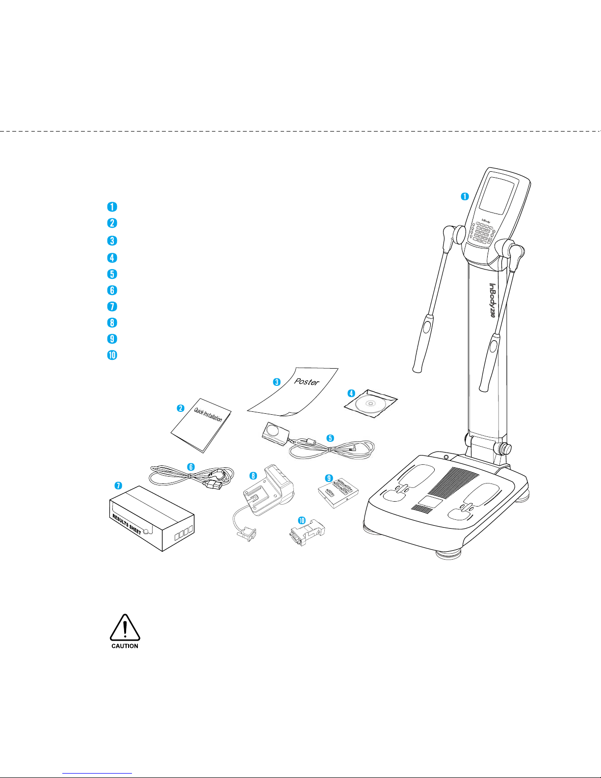
When opening the box, check to ake sure of all the following ite s are included.
A. Product Units
InBody230
InBody230 Quick Installation Guide
InBody230 Poster 1 EA
User’s Manual CD
Adapter (12V, 3.5A) 1EA
Power Cord (AC 250V 10A 1.8 ) 1EA
Result Sheet Box 1Box (optional)
Ther al Printer 1EA (optional)
SD400 (optional)
Serial Gender (optional)
.USB Cable is to be purchased separately for connecting the printer.
2.The printer is needed for printing the result sheets.
Please check the compatibility of the printer with ydoBnI .
1. Contents o the Box

B. Package
1) Package Box
Box size: 480(W) 940(L) 340(H); 1 EA
2) Packing Pad
Top Pad 1EA
Botto Pad 1EA
Chapter 1 Installation and Maintenance
1-2
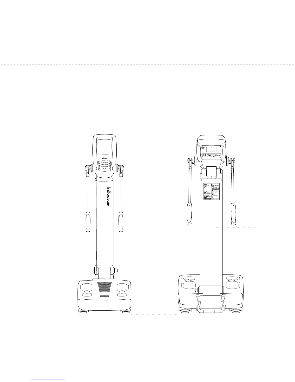
Individual part identification and functions with sche atic sketches are provided
below. Please inspect each co ponent of the InBody230 before installation to
ensure there are no scratches or da age.
A. Operation Part
B. Upper Part
C. Lower Part
D. Rear Part
A.Operation Part
B. Upper Part
C.Lower Part
D.Rear Part
2. Exterior & Functions

A. Operation Part
(1) LCD Monitor (320 240 color STN LCD)
This displays the analysis procedure, essages and results.
(2) Key Pad (23 buttons)
The keypad is divisible into input buttons and function buttons.
These are used to input data required for body
co position analysis, to set up the operating environ ent and
to print out test results.
B. Upper Part
(1) Thu b Electrode
Activated by aking contact with the thu b, thus allowing
current to flow through the body during easure ent.
(2) Pal Electrode
Activated by wrapping the pal around the electrode, thus
allowing current to flow through the body during easure ent.
(3) Hand Electrode Joint and Hand Electrode Bar
Supports Hand Electrode and contains electric cables.
Chapter 1 Installation and Maintenance
3-4
Hand Electrode Bar
Hand Electrode Joint
Thu b Electrode
Pal Electrode

(4) Body Stand
C. Lower Part
(1) Front Sole Electrode
Activated by placing the fore-foot directly on the front sole electrode. This allows the
current to flow through the body.
(2) Rear Sole Electrode
Activated by placing the heel of the foot directly on the rear sole electrode.
(3) Base Fra e
The loadcell, which easures body weight, is underneath the Base Fra e.
(4) Joint Fra e
Connects upper part and lower part.
(5) Joint Screw
Used to fix the stand after raising it.
Level Indicator
Front Sole Electrode
Rear Sole Electrode
Joint Fra e
Base Fra e
Joint Screw
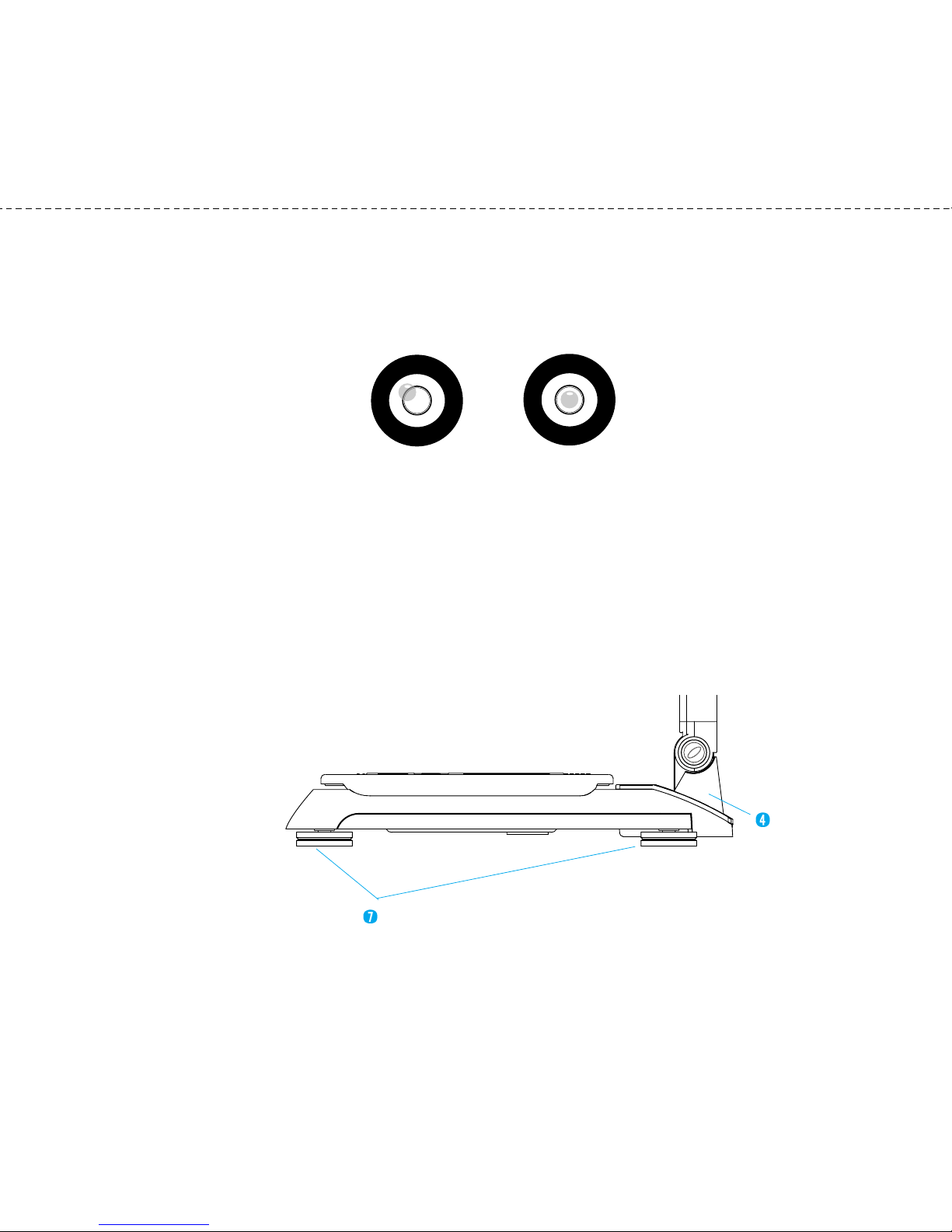
(6) Level Indicator
Used to level the InBody230 by eans of a view glass and bubble align ent.
<Un-leveled State> <Leveled State>
(7) Level Screws
There are 4 leveling screws that support the equip ent. Leveling screws are
designed to be turned by hand, so you can easily adjust the balance of the
equip ent.
Joint Fra e
Level Screws
Chapter 1 Installation and Maintenance
5-6
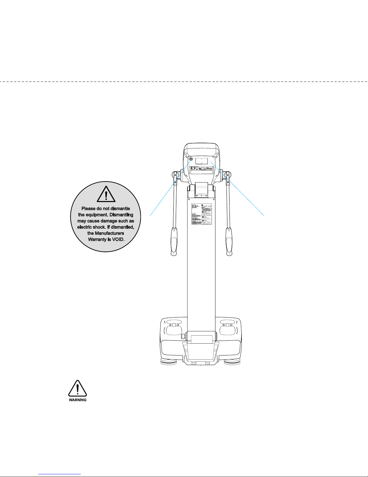
D. Rear Part
(1) Back Cover
Only qualified personnel are allowed to remove the back cover.
Do not dismantle the equipment or open the back cover. Internal parts are not for customer
use and it may cause electric shock. If the equipment is dismantled, the warranty is void, and
service costs will be charged.
< arning sticker>
Back Cover
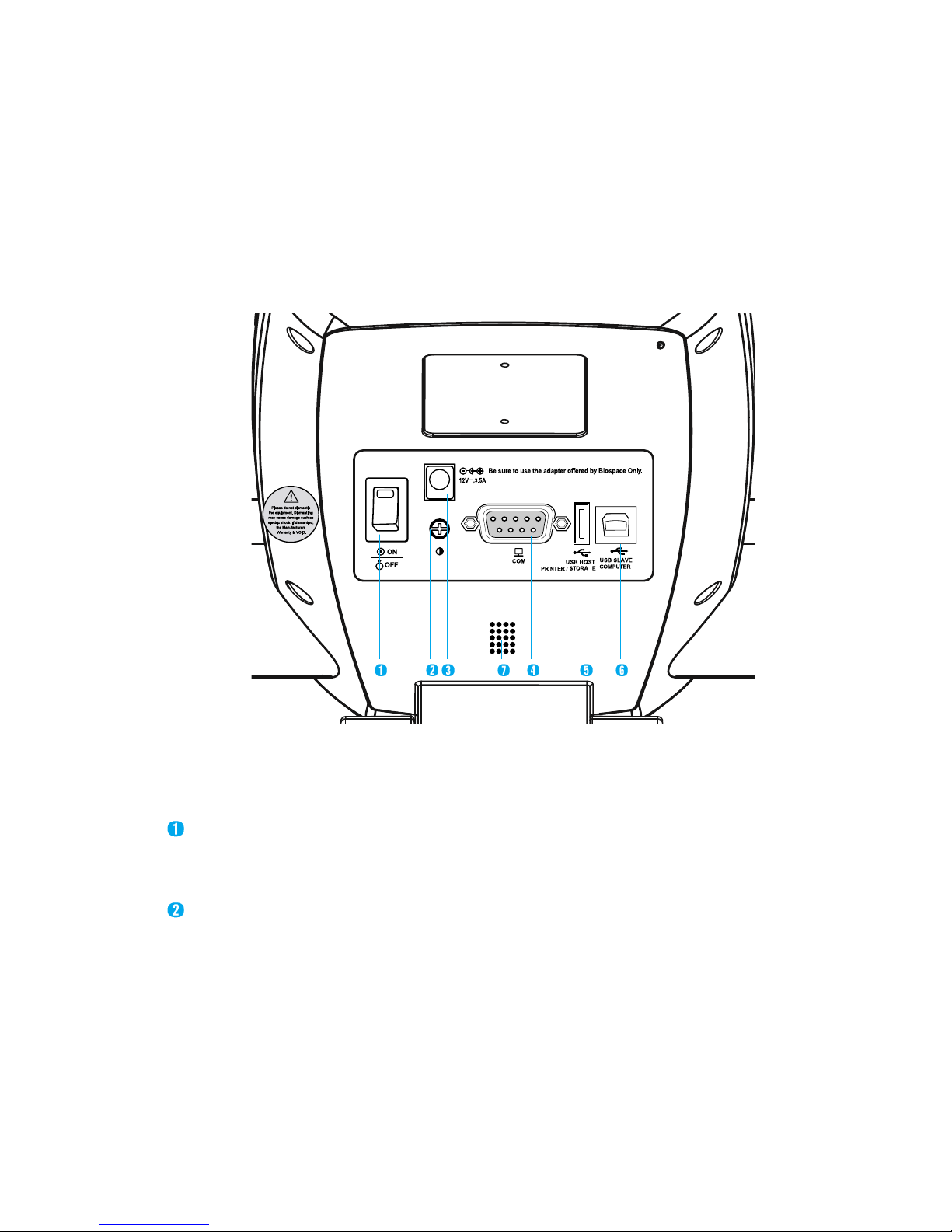
(2) Control & Connection Unit
Connects to peripherals such as a PC or a printer for data transmission.
Power Switch
Power the InBody23 on/off.
LCD Bright Control
Used to adjust LCD brightness. Turn left to brighten and turn right to darken.
G
Chapter 1 Installation and Maintenance
7-8

Power Input Port
Used to connect the power adapter.
9pin Serial Port, Fe ale (RS232C)
Used to connect optional devices such as ther al printer or blood pressure onitor. Using
SD400(Serial Distributor) provided by ydoBnI , the axi u of 4 devices can be
connected at once.
USB Host Port
Used to interface with a USB printer or a USB Storage Device.
You can use either of the two USB ports interchangeably.
USB Slave Port
Used to connect with a PC using Lookin’ Body.
Use only the power cord provided by ydoBnI to connect to the power port.
When you use the adapter cable, insert the adapter cable tightly into the InBody230.
Including the optional equipment, only the peripherals provided by ydoBnI can be
connected to the InBody230. For any inquiry about peripherals, contact ydoBnI .
(3) Speaker
A signal sound infor s users of status such as process or co pletion of easure ent.
<Darker> <Brighter>
Other manuals for 230
1
Table of contents
Other inbody Measuring Instrument manuals


inbody
inbody PUSH User manual

inbody
inbody InBody270 User manual

inbody
inbody 970 User manual

inbody
inbody BPBIO210 User manual

inbody
inbody 720 User manual

inbody
inbody BSM 370 User manual

inbody
inbody BSM 370 User manual

inbody
inbody 720 User manual

inbody
inbody BSM170 User manual

inbody
inbody H30NWi User manual

Popular Measuring Instrument manuals by other brands

Endress+Hauser
Endress+Hauser Solicap M FTI55 Safety instructions

KROHNE
KROHNE OPTISWIRL 4200 Series Supplementary instructions

Endress+Hauser
Endress+Hauser Deltapilot M FMB50 Brief operating instructions

KROHNE
KROHNE OPTISYS TUR 1060 Handbook

Kestrel
Kestrel 5000 Troubleshooting

Lumel
Lumel N27D user manual


