manuals.online logo
Brands
  1. Home
  2. •
  3. Brands
  4. •
  5. iNels
  6. •
  7. Switch
  8. •
  9. iNels RFJA-32B User manual

iNels RFJA-32B User manual

02-3/2018 Rev.4
RFJA-12B, RFJA-32B
Switch unit for shutters
EN
Made in Czech Republic
RFJA-12B/230V, RFJA-12B/120V
RFJA-32B/230V, RFJA-32B/120V
RFJA-12B/24VDC
RFJA-32B/24VDC
1/4
Characteristics /
• The switching unit for blinds has 2 output channels used to control garage doors, gates, blinds,
awnings, etc.
• It can be combined with Control or System units iNELS RF Control.
• The BOX design lets you mount it right in an installation box, a ceiling or motor drive cover.
• RFJA-12B/230V (120V): connection of switched load 2x 8 A (2x 2 000 W).
• RFJA-12B/24VDC: contactless quiet switching.
• RFJA-32B/230V (120V): connection of switched load 2x 8 A (2x 2 000 W), with the ability to con-
nect existing buttons.
• RFJA-32B/24VDC: contactless quiet switching with the ability to connect existing buttons.
• Short presses of the controller enable tilting of lamellas, and a long press enables you to draw
the blinds up or down to the end position.
• Each of the units may be controlled by up to 25 channels (1 channel represents one assigned
controller).
• The programming button on the unit is also used for manual control of the output.
• For components it is possible to set the repeater function via the RFAF / USB service device.
• Range up to 100 m (in open space), if the signal is insufficient between the controller and unit,
use the signal repeater RFRP-20 or protocol component RFIO2that support this feature.
• Communication frequency with bidirectional protocol iNELS RF Control2(RFIO2).
Assembly /
mounting into a non-conducting drive housing flush mounting ceiling mounted
Connection /
L
N
PE
M
M
LN
+
-
5-24V DC


-+
M
M
(Without terminal blocks /
(With Terminal Blocks for switch Up and Down Buttons /
(Without terminal blocks /
(With Terminal Blocks for switch Up and Down Buttons /
Aktor żaluzjowy
PL
ELKO EP, s.r.o. | Palackého 493 | 769 01 Holešov, Všetuly | Czech Republic | e-mail: [email protected] | Support: +420 778 427 366
ELKO EP Poland, sp. z o. o. | ul. Motelowa 21 | 43-400 Cieszyn | Polska | e-mail: [email protected] | GSM: +48 785 431 024
www.elkoep.com / www.elkoep.pl
Charakterystyka
• Aktor przełączający do żaluzji ma 2 kanały wyjściowe, służące do sterowania bramami garażowymi,
bramkami, żaluzjami, markizami...
• Można go połączyć ze sterownikami oraz urządzeniami systemowymi iNELS RF Control.
• Wykonanie BOX pozwala na montaż do puszki instalacyjnej, sufitu lub pokrywy napędu.
• RFJA-12B/230V: podłączenie włączanego obciążenia 2 x 8A (2 x 2000W).
• RFJA-12B/24VDC: bezstykowe ciche przełączanie.
• RFJA-32B/230V (120V): podłączenie załączanego obciążenia 2x 8 A (2x 2000 W), z możliwością
podłączenia istniejących przycisków.
• RFJA-32B/24VDC: bezstykowe ciche załączanie z możliwością podłączenia istniejących przycisków.
• Krótkie naciśnięcia sterownika pozwala na poziome wychylanie listew, długie naciśnięcie spowo-
duje wyciągnięcie / opuszczenie żaluzji do pozycji krańcowej.
• Każdy aktor może być sterowany aż z 25 kanałów (1 kanał reprezentuje jeden przypisany sterownik).
• Przycisk do programowania na urządzeniu służy również do ręcznego sterowania wyjściem.
• W urządzeniach oznaczonych jako iNELS RF Control2(RFIO2) można ustawić funkcję wzmacniacza
sygnału (repeatera) za pomocą urządzenia serwisowego RFAF/USB.
• Zasięg do 100 m (w wolnej przestrzeni), w przypadku niewystarczającego sygnału pomiędzy
sterownikiem oraz urządzeniem użyj wzmacniacza sygnału (repeatera) RFRP-20 lub urządzenia s
protokołem RFIO2, wspierającego tę funkcję.
• Częstotliwość komunikacji z dwukierunkowym protokołem iNELS RF Control2(RFIO2).
Montaż
montaż do nieprzewodzącej pokrywy napędu montaż do puszki instalacyjnej montaż w suficie
Podłączenie
bez bloku zacisków)
z blokami zacisków do podłączenia przycisków góra / dół)
bez bloku zacisków)
z blokami zacisków do podłączenia przycisków góra / dół)
02-3/2018 Rev.4
RFJA-12B, RFJA-32B
Switch unit for shutters
EN
Made in Czech Republic
☺
☺
☺
☺

☺
RFRP-20
Radio frequency signal penetration through various construction materials /
60 - 90 % 80 - 95 % 20 - 60 % 0 - 10 % 80- 90 %
brick walls wooden structures
with plaster boards reinforced
concrete metal partitions common glass
For more information, see“Installation manual iNELS RF Control”:
http://www.elkoep.com/catalogs-and-brochures
Indication, manual control /
button / LED
• LED STATUS - indication of the device status.
• Manual control is performed by pressing the PROG button.
• Programming is performed by pressing the PROG button for more than 1s.
• Terminal block for connection of buttons. IN1 - direction button up IN2- button down.
In the programming and operating mode, the LED on the component lights up at the
same time each time the button is pressed - this indicates the incoming command.
button / terminal board /
LED
RFJA-32BRFJA-12B
1
PROG < 1s
X x
2
PROG > 1s
1 x
5

=1s ... 4min. + 2s
4
PROG > 5s
1 x
3

1 x

<3 s

Functions and programming with RF transmitters /
Function description /
Shooting fins, short travel. Blinds starts / descend to the end position.
Programming /
Repeatedly press of program-
ming button on actuator RFJA
for no longer then 1 second
will roll up shutters into final
upper position.
Press of programming button
on actuator RFJA for 1 second
will activate actuator RFJA into
programming mode. LED is
flashing in 1s interval.
Select and press one button
on wireless switch, to this but-
ton will be assigned Function
1. Second control position
“down”, will be assigned auto-
matically (on the same half of
wireless switch).
Press of programming button
longer then 5 seconds, will
activate actuator into timing
mode. LED flashs 2x in each
1s interval.
Press of the button on wireless switch with assigned function for shutters
down will roll the shutters down. Release the press of this button 2 seconds
after the shutter is stopped by lower final switch.

>3 s

2/4
Aktor żaluzjowy
PL
ELKO EP, s.r.o. | Palackého 493 | 769 01 Holešov, Všetuly | Czech Republic | e-mail: [email protected] | Support: +420 778 427 366
ELKO EP Poland, sp. z o. o. | ul. Motelowa 21 | 43-400 Cieszyn | Polska | e-mail: [email protected] | GSM: +48 785 431 024
www.elkoep.com / www.elkoep.pl
Przenikanie fal radiowych przez różnego rodzaju materiały budowlane
ściana z cegły
konstrukcje drewniane
z płytami gipsowo-
kartonowymi
ściana
żelbetowa ścianki
metalowe zwykłe szkło
Sygnalizacja, sterowanie ręczne
przycisk PROG
• LED STATUS - sygnalizacja stanu pracy urządzenia.
• Sterowanie ręczne poprzez naciśnięcie przycisku PROG < 1s.
• Programowanie poprzez naciśnięcie przycisku PROG > 1s.
• Blok zacisków do podłączenia przycisków. IN1 - przycisk Góra, IN2 - przycisk Dół.
W trybie programowania oraz usuwania każde naciśnięcie przycisku sterownika
równocześnie na długo świeci LED na urządzeniu - przez co sygnalizuje odbiór polecenia.
Funkcje oraz programowanie ze sterowników RF
Opis funkcji
Wychylanie listew, krótki ruch. Żaluzja opuści się / wyciągnie do pozycji krańcowej.
Programowanie
Powtarzanymi naciśnięciami
przycisku PROG na urządzeniu
RFJA na mniej niż 1 sekundę,
żaluzje zostaną wyciągnięte
do górnej pozycji krańcowej.
Po naciśnięcie przycisku PROG
na urządzeniu RFJA na 1 se-
kundę, urządzenie wchodzi
w tryb programowania. Dioda
LED miga w odstępie 1s.
Naciśnięcie wybranego przy-
cisku na sterowniku RF przy-
pisze funkcję "w górę". Pozycja
druga sterowania - "w dół"
- zostaje przypisana automa-
tycznie (przy 4-przyciskowym
sterowniku RF, w tej samej
połowie).
Po naciśnięcie przycisku
PROG na dłużej niż 5 sekund,
urządzenie wchodzi w tryb
ustawienia czasu. Dioda LED
2x mignie w odstępie 1s.
Naciśnięcie wybranego przycisku na sterowniku RF, przypisanego do opusz-
czenia żaluzji, spowoduje jej opuszczanie. Zwolnij przycisk po 2 sekundach od
zatrzymania się żaluzji w dolnej pozycji krańcowej.
przycisk PROG
Szczegółowe informacje znajdziesz na stronie “Installation manual iNELS RF Control”:
http://www.elkoep.com/catalogs-and-brochures
listwa zaciskowa
02-3/2018 Rev.4
RFJA-12B, RFJA-32B
Switch unit for shutters
EN
Made in Czech Republic
6

=1s ... 4min.

+ 2s
7
PROG < 1s
1 x
xxxxxx
3/4
Press of the button on wireless switch with assigned function for shutters up
will roll the shutters up. Release the press of this button 2 seconds after the
shutter is stopped by upper final switch. Duration of rolling up and down is
than saved into memory of reciever.
Press of programming button
on reciever RFJA shoter then
1 second will finish program-
ming mode (LED switches
off).
Programming with RF control units /
adress / The address listed on the front of the actuator is used for programming and
controlling actuators by RF control units.
PROG > 5s
1 x PROG > 8s
1 x
Delete actuator /
Deleting one position of the transmitter /
By pressing the programming button on the actuator for 5 sec-
onds, deletion of one transmitter activates. LED flashs 4x in each
1s interval.
Pressing the required button on the transmitter deletes it from
the actuator's memory.
The LED goes out and the actuator returns to operating mode.
Deleting the entire memory /
By pressing the programming button on the actuator for 8 sec-
onds, deletion occurs of the actuator's entire memory. LED
flashs 4x in each 1s interval.
The actuator goes into the programming mode, the LED flashes
in 0.5s intervals (max. 4 min.).
You can return to the operating mode by pressing the Prog but-
ton for less than 1s.
Aktor żaluzjowy
PL
ELKO EP, s.r.o. | Palackého 493 | 769 01 Holešov, Všetuly | Czech Republic | e-mail: [email protected] | Support: +420 778 427 366
ELKO EP Poland, sp. z o. o. | ul. Motelowa 21 | 43-400 Cieszyn | Polska | e-mail: [email protected] | GSM: +48 785 431 024
www.elkoep.com / www.elkoep.pl
Naciśnięcie wybranego przycisku na sterowniku RF, przypisanego do wycią-
gania żaluzji, spowoduje jej wyciąganie. Zwolnij przycisk po 2 sekundach od
zatrzymania się żaluzji w górnej pozycji krańcowej. Po naciśnięciu przycisku
PROG na urządzeniu RFJA
krótszym niż 1 sekunda, na-
stępuję koniec trybu progra-
mowania (LED gaśnie).
Programowanie z urządzeń systemowych
adres Do zaprogramowania oraz sterowania urządzeniami RF z urządzeń syste-
mowych, służy adres podany na przedniej stronie urządzenia.
Kasowanie ustawień urządzenia
Kasowanie jednej pozycji sterownika
Po naciśnięciu przycisku PROG na urządzeniu RFJA na 5 s, uak-
tywni się kasowanie jednej pozycji sterownika. LED 4-krotnie w
odstępach 1 sekundowych mignie.
Naciśnięcie przypisanego przycisku na sterowniku usunie usta-
wienia z pamięci urządzenia.
Dioda LED zgaśnie, urządzenie wróci do trybu roboczego.
Kasowanie całej pamięci
Po naciśnięciu przycisku PROG na urządzeniu RFJA na 8 s, skaso-
wana zostanie cała pamięć urządzenia. LED 4-krotnie w odstę-
pach 1 sekundowych mignie.
Urządzenie wchodzi w tryb programowania, dioda LED miga w
odstępie 0.5s (przez maks. 4 min).
Powrót do trybu roboczego następuje po naciśnięciu przycisku
PROG na mniej niż 1 s.
02-3/2018 Rev.4
RFJA-12B, RFJA-32B
Switch unit for shutters
EN
Made in Czech Republic
4/4
Technical parameters /
* For RFJA-32BV only.
** Identical with supply voltage.
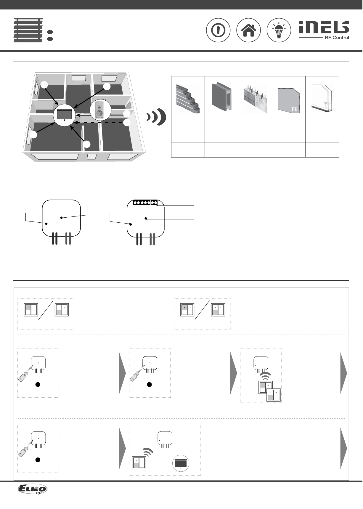
Attention:
When you instal iNELS RF Control system, you have to keep minimal distance 1 cm between each units.
Between the individual commands must be an interval of at least 1s.
Supplyvoltage:
Apparent input:
Dissipated power:
Power without load:
Power under load:
Supplyvoltagetolerance:
Input
Inpot:
Output
Number of contacts:
Rated current:
Permanent current:
Switching power:
Peak current:
Switching voltage:
Switching output voltage:
Mechanical service life:
Electrical service life(AC1):
Control
RF, by command from transmitter:
Manual control:
Rangein free space:
Other data
Operating temperature:
Operating position:
Mounting:
Protection:
Overvoltagecategory:
Contamination degree:
Terminal:
Terminals:
Length of terminals:
Dimensions:
Weight:
Related standards:
RFJA-12B/230V RFJA-12B/120V RFJA-12B/24VDC
RFJA-32B/230V RFJA-32B/120V RFJA-32B/24VDC
Warning
Instruction manual is designated for mounting and also for user of the device. It is always a part of its packing. Instal-
lation and connection can be carried out only by a person with adequate professional qualification upon under-
standing this instruction manual and functions of the device, and while observing all valid regulations. Trouble-free
function of the device also depends on transportation, storing and handling. In case you notice any sign of damage,
deformation, malfunction or missing part, do not install this device and return it to its seller. It is necessary to treat
this product and its parts as electronic waste after its lifetime is terminated. Before starting installation, make sure
that all wires, connected parts or terminals are de-energized. While mounting and servicing observe safety regula-
tions, norms, directives and professional, and export regulations for working with electrical devices. Do not touch
parts of the device that are energized – life threat. Due to transmissivity of RF signal, observe correct location of
RF components in a building where the installation is taking place. RF Control is designated only for mounting in
interiors. Devices are not designated for installation into exteriors and humid spaces. The must not be installed into
metal switchboards and into plastic switchboards with metal door – transmissivity of RF signal is then impossible.
RF Control is not recommended for pulleys etc. – radiofrequency signal can be shielded by an obstruction, inter-
fered, battery of the transceiver can get flat etc. and thus disable remote control.
5-24 VDC
x
x
0.5 W
20 W


x
x
0.8 A
x
1.5 A / < 3 s
x
5-24 VDC**
x
x
Aktor żaluzjowy
PL
ELKO EP, s.r.o. | Palackého 493 | 769 01 Holešov, Všetuly | Czech Republic | e-mail: [email protected] | Support: +420 778 427 366
ELKO EP Poland, sp. z o. o. | ul. Motelowa 21 | 43-400 Cieszyn | Polska | e-mail: [email protected] | GSM: +48 785 431 024
www.elkoep.com / www.elkoep.pl
Dane techniczne
* Tylko dla RFJA-32B.
** Identyczne z napięciem zasilania.
Napięcie zasilania:
Moc pozorna:
Moc rozproszona:
Pobórmocy bez obciążenia:
Pobórmocy zobciążeniem:
Tolerancjanapięcia zasilania:
Wejścia
Wejście:
Wyjścia
Ilość styków:
Prądznamionowy:
Prądciągły:
Moc włączana:
Prądszczytowy:
Napięcie włączane:
Napięcie włączane na wyjściu:
Trwałość mechaniczna:
Trwałość elektryczna (AC1):
Sterowanie
Polecenie RF ze sterownika:
Sterowanie ręczne:
Zasięg w wolnej przestrzeni:
Pozostałedane
Temperatura robocza:
Pozycjarobocza:
Umocowanie:
Szczelność:
Kategoria przepięcia:
Stopień zanieczyszczenia:
Blok zacisków:
Zaciski:
Długość zacisków:
Wymiary:
Waga:
Normy:
230VAC/ 50 -60 Hz120 VAC/ 60 Hz
7 VA / cos φ = 0.1 7 VA / cos φ = 0.1
0.7 W 0.7 W
x
x
+10 -15 %
2x switching or expansion against GND/ 2x przełączny lub rozłączny do GND*
2x switching / przełączane (AgSnO2)
8A / AC1
x
2000 VA / AC1
10 A / < 3 s
250 VAC1
x
1x107
1x10⁵
866 MHz, 868 MHz, 916 MHz
PROG (STOP, %, STOP, &)
up to / do 100 m
-15 ... + 50 °C
any / dowolna
free at lead-in wires / luźne na przewodach doprowadzających
IP30
III.
2
0.5 -1mm2*
CY wire, cross section / przewódCY, średnica 4 x 0.75mm2
90 mm
49x 49x 21 mm 49x 49x 13 mm
46g 22 g
EN 60669, EN 300220, EN 301489 R&TTE Directive, Order. No426/2000 Coll.(Directive 1999/EC) /
EN 60669, EN 300 220, EN 301 489 dyrektywaRTTE, NVč.426/2000Sb(dyrektywa1999/ES)
Uwaga:
Podczas instalacji systemu iNELS RF Control koniecznym jest dotrzymanie minimalnej odległości
1 cm pomiędzy elementami.
Wymagany jest odstęp min. 1s pomiędzy kolejnymi poleceniami.
Ostrzeżenie
Instrukcja obsługi służy do celów montażu oraz dla użytkowników urządzeń. Instrukcja obsługi zawsze wchodzi
w skład opakowania urządzenia. Montaż oraz podłączenie mogą wykonywać wyłącznie osoby z odpowiednimi
kwalifikacjami zawodowymi, zgodnie z obowiązującymi przepisami, które w odpowiedni sposób zapoznały się z
instrukcją obsługi oraz działaniem urządzeń. Bezproblemowe działanie urządzeń jest również zależne od wcze-
śniejszego sposobu transportu, magazynowania oraz manipulacji. W przypadku wykrycia jakichkolwiek oznak
uszkodzenia, odkształcenia, awarii lub brakujących elementów, prosimy o nieinstalowanie urządzenia oraz zwró-
cenie się do sprzedawcy. Urządzenie lub jego części muszą być potraktowane po końcu okresu używania jako
odpad elektroniczny. Przed rozpoczęciem instalacji należy upewnić się, że wszystkie przewody, podłączone części
lub terminale nie są pod napięciem. W trakcie montażu lub konserwacji koniecznym jest dotrzymanie przepisów
bezpieczeństwa, norm, dyrektyw oraz przepisów branżowych, dotyczących pracy z urządzeniami elektrycznymi.
Nie należy dotykać części urządzeń pod napięciem - ryzyko zagrożenia życia. Ze względu na właściwe przenikanie
fal radiowych RF, pamiętaj o właściwym umieszczeniu urządzeń w budynku, w którym są instalowane. Urządzenia
RF Control są przeznaczone wyłącznie do montażu wewnątrz budynków. Urządzenia nie mogą być instalowane na
zewnątrz lub w pomieszczeniach wilgotnych, dalej nie mogą być instalowane w metalowych szafach rozdzielczych
lub plastikowych szafach rozdzielczych z metalowymi drzwiami - uniemożliwi prawidłowe przenikanie fal radio-
wych. Urządzeń RF Control nie należy używać do sterowania urządzeniami o podwyższonym ryzyku, takimi jak
pompy, el. urządzenia grzewcze bez termostatu, windy, dźwigi, itp. - przepływ fal radiowych może być przerwany,
naruszony przez przeszkodę, bateria nadajnika może być rozładowana itp. Z wyżej wymienionych powodów może
dojść do zakłócenia lub uniemożliwienia sterowania.

This manual suits for next models

1

Other iNels Switch manuals

iNels RFSAI-62B/230V User manual

iNels

iNels RFSAI-62B/230V User manual

iNels RFSA-61M User manual

iNels

iNels RFSA-61M User manual

iNels RFSA-61M User manual

iNels

iNels RFSA-61M User manual

iNels RFSA-11B User manual

iNels

iNels RFSA-11B User manual

iNels RFSA-61M User manual

iNels

iNels RFSA-61M User manual

iNels RFSA-61M User manual

iNels

iNels RFSA-61M User manual

iNels RFSAI-61B User manual

iNels

iNels RFSAI-61B User manual

iNels RFSOU-1 User manual

iNels

iNels RFSOU-1 User manual

iNels RFSA-61B User manual

iNels

iNels RFSA-61B User manual

iNels RFSAI-62B User manual

iNels

iNels RFSAI-62B User manual

iNels RFSA-66MI User manual

iNels

iNels RFSA-66MI User manual

iNels RFJA-12B User manual

iNels

iNels RFJA-12B User manual

iNels RFSOU-1 User manual

iNels

iNels RFSOU-1 User manual

iNels RFSA-61M/MI User manual

iNels

iNels RFSA-61M/MI User manual

iNels RFSAI-61B User manual

iNels

iNels RFSAI-61B User manual

iNels RFSAI-11B-SL User manual

iNels

iNels RFSAI-11B-SL User manual

iNels RFSA-61MI User manual

iNels

iNels RFSA-61MI User manual

iNels RFSA-66M User manual

iNels

iNels RFSA-66M User manual

iNels RFSA-61M User manual

iNels

iNels RFSA-61M User manual

iNels RFSTI-11 User manual

iNels

iNels RFSTI-11 User manual

iNels RFSAI-11B-SL User manual

iNels

iNels RFSAI-11B-SL User manual

iNels RFSA-61M User manual

iNels

iNels RFSA-61M User manual

iNels RF KEY-40/W User manual

iNels

iNels RF KEY-40/W User manual

iNels RFJA-32B-SL User manual

iNels

iNels RFJA-32B-SL User manual

Popular Switch manuals by other brands

ICP DAS USA FSM-6228G quick start

ICP DAS USA

ICP DAS USA FSM-6228G quick start

Inficon VSC150 operating manual

Inficon

Inficon VSC150 operating manual

INSTEON 2242-222 quick start guide

INSTEON

INSTEON 2242-222 quick start guide

DCN S5750E Series installation guide

DCN

DCN S5750E Series installation guide

Vicon V1404L Instructions for installation and operation

Vicon

Vicon V1404L Instructions for installation and operation

Lindy 43141 user manual

Lindy

Lindy 43141 user manual

VOLKTEK NSH-9308P user manual

VOLKTEK

VOLKTEK NSH-9308P user manual

D-Link GO-SW-5E Features & specifications

D-Link

D-Link GO-SW-5E Features & specifications

Armacost Lighting AL-28068 quick start guide

Armacost Lighting

Armacost Lighting AL-28068 quick start guide

Enterasys A4H124-24 Hardware installation guide

Enterasys

Enterasys A4H124-24 Hardware installation guide

Asante IntraCore 3524-2G supplementary guide

Asante

Asante IntraCore 3524-2G supplementary guide

BEP Marinco 770-EZ quick start guide

BEP

BEP Marinco 770-EZ quick start guide

Cisco 2950 - Catalyst Switch Software configuration guide

Cisco

Cisco 2950 - Catalyst Switch Software configuration guide

AVARRO 0E-HDMISW3X1 manual

AVARRO

AVARRO 0E-HDMISW3X1 manual

TRENDnet THA?101 user guide

TRENDnet

TRENDnet THA?101 user guide

Nortel Contivity 600 Installing

Nortel

Nortel Contivity 600 Installing

Ihse MV42 Series user manual

Ihse

Ihse MV42 Series user manual

TRENDnet TEG-30102WS user guide

TRENDnet

TRENDnet TEG-30102WS user guide

manuals.online logo
manuals.online logoBrands
  • About & Mission
  • Contact us
  • Privacy Policy
  • Terms and Conditions

Copyright 2025 Manuals.Online. All Rights Reserved.